Insys 11-02-01-01-43.003 User manual
- Category
- Modems
- Type
- User manual
This manual is also suitable for

Operating Manual
INSYS Modem 56k
small INT 2.0
INSYS Modem 56k
small INT USB 1.0
June 06

2 June 06
Copyright © June 06 INSYS MICROELECTRONICS GmbH
Any duplication of this manual is prohibited. All rights on this documentation
and the devices are with INSYS MICROELECTRONICS GmbH Regensburg.
Restrictions of guarantee
This handbook contains a concise description. The compilation of the text has
been performed with utmost care. Despite all efforts, there may be deviations
to the actual functions. No guarantee can therefore be given for the accuracy of
the contents. We can neither assume legal responsibility nor any liability for
incorrect information and their consequences. Suggestions for improvements
and comments are always welcome.
Trademarks and logos
The use of a trademark or logo not shown below does not indicate that it is
freely available for use.
MNP is a registered trademark of Microcom Inc.
IBM PC, AT, XT are registered trademarks of International Business Machine Corporation.
INSYS ® is a registered trademark of INSYS MICROELECTRONICS GmbH.
Windows™ is a registered trademark of Microsoft Corporation.
Publisher:
INSYS MICROELECTRONICS GmbH
Waffnergasse 8
93047 Regensburg, Germany
Phone: 0941/58692-0
Fax: 0941/563471
E-mail: [email protected]
Internet: http://www.insys-tec.de
Subject to technical changes. Errors excepted.
Date:
June 06
Item number: 31-22-03.051 English

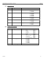
INSYS Modem 56k small INT 2.0/USB 1.0 Contents
June 06 3
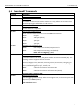
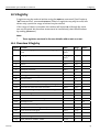
1 SCOPE OF DELIVERY....................................................6
2 FUNCTION OVERVIEW................................................6
3 NOTES REGARDING THE USE OF THE MANUAL..........7
4 INITIAL OPERATION ....................................................8
4.1 FRONT PANEL ............................................................................8
4.2 TOP.........................................................................................9
4.3 USER PROFILES ..........................................................................9
4.4 INSTALLATION .........................................................................10
4.5 INSTALLATION OF A USB DRIVER ................................................12
5 FUNCTIONS...............................................................19
5.1 CONFIGURATION .....................................................................19
5.2 SERIAL DATA TRANSMISSION .....................................................21
5.3 ERROR CORRECTION .................................................................25
5.4 DATA COMPRESSION ................................................................25
5.5 SELECTIVE CALL ANSWER...........................................................27
5.6 SEND MESSAGES .....................................................................29
5.7 REMOTE CONFIGURATION (REMOTE CONTROL).............................31
5.8 ACCESS CONTROL ....................................................................33
5.9 DATA TRANSMIT CONTROLLER (IDLE CONNECTION CONTROL)..........35

Contents INSYS Modem 56k small INT 2.0/USB 1.0
4 June 06
5.10 PRIORITY CIRCUIT FOR MODEMS WITH PHONES CONNECTED IN SERIES
36
6 CONFIGURATION SOFTWARE HSCOMM ..................39
7 OPERATION WITH A PLC...........................................40
8 FIRMWARE UPDATE .................................................41
8.1 FLASHCOM.EXE .......................................................................41
8.2 TERMINAL PROGRAM................................................................42
9 AT COMMAND SET ...................................................44
9.1 OVERVIEW AT COMMANDS.......................................................45
9.2 OVERVIEW FAX AND VOICE COMMANDS .....................................70
9.3 AT MESSAGES.........................................................................70
10 S REGISTRY ...............................................................73
10.1 OVERVIEW S REGISTRY .............................................................73
10.2 DESCRIPTION S REGISTRY ..........................................................74
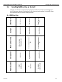
11 SENDING SMS AS FAX OR E-MAIL ............................83
11.1 SMS AS FAX ...........................................................................83
11.2 SMS AS E-MAIL .......................................................................84
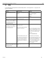
12 FAQ...........................................................................85
13 SAFETY INSTRUCTIONS.............................................87
13.1 GENERAL................................................................................87

INSYS Modem 56k small INT 2.0/USB 1.0 Contents
June 06 5
13.2 CLEANING...............................................................................87
14 TECHNICAL DATA......................................................88
14.1 MECHANICAL FEATURES............................................................88
14.2 POWER SUPPLY .......................................................................88
14.3 PC INTERFACE .........................................................................89
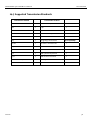
14.4 POSSIBLE INTERFACE SPEEDS ......................................................90
14.5 SUPPORTED TRANSMISSION STANDARDS .....................................91
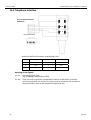
14.6 TELEPHONE INTERFACE..............................................................92
14.7 ITU STANDARDS (CCITT)..........................................................93
15 COUNTRY CODES......................................................94

Scope of Delivery INSYS Modem 56k small INT 2.0/USB 1.0
6 June 06
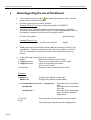
1 Scope of Delivery
Before you begin with the initial operation, please check if all accessories are in-
cluded in the box.
¾ INSYS Modem 56k small INT 2.0 or
INSYS Modem 56k small INT USB 1.0
¾ 2 phone cords (TAE N at RJ12 and RJ12 at RJ12)
¾ PC connection cable
9/9-pin (RS232 cable) or USB connection cable
¾ User Guide
¾ CD-ROM (optional)
Please contact your supplier if the content is not complete. Please also check the
modem for shipping damage. Please also refer to your supplier if anything is dam-
aged.
Please keep the packaging material for possible future shipping or storage.
2 Function Overview
The INSYS Modem 56k small INT is a modem for the analogue telephone network.
It has a very compact design and very robust plastic housing. The modem sup-
ports the following functions, which are described in detail in Chapter 5:
¾ Usage in 87 countries
¾ Establishing a data connection
¾ Auto answer
¾ Data flow control
¾ Error correction
¾ Data compression
¾ Idle connection control
¾ Firmware Update
¾ Remote configuration
¾ Security callback

INSYS Modem 56k small INT 2.0/USB 1.0 Notes Regarding the Use of the Manual
June 06 7
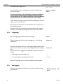
3 Notes Regarding the Use of the Manual
¾ This manual uses the symbol for especially important notes. Further
notes will be marked accordingly.
¾ All factory settings are marked “default”.
Example (Chap. 5.7.3): Enter old password (default: QWERTY)
¾ In Chapters 4 to 6 the description consists of two columns. Individual
functions are described on the left side. The according AT commands and
the modem responses can be found in the right column.
Function description AT command
Example (Chap. 5.2.7):
After the hardware reset, load the user profile 1 ATZ1
¾ All AT commands start with the letters AT and end with a “Return” (Car-
riage Return - CR). AT commands can be entered in capital or small let-
ters. The command is evaluated as soon as the modem received a re-
sponse.
¾ In the following, the used syntax is explained:
c ATDT AT command (font: Courier, bold)
d <Expression> Input of a parameter (font: Courier, bold)
e <Expression> Input of an optional parameter
(Font: Courier, bold)
f Expression Response from the modem (font: italic)
Examples:
c ATDT<n> Dialing of the phone number <n>
ATDT1234 Dialing of the phone number 1234
d+e AT+MS=<Modulation>, [Automode] Selection of the modulation
type
AT+MS=V92 Selection of the modulation
type V.92
AT+MS=V92,1 Selection of the modulation
typeV.92 with automatic
adjustment
f Connect The connection to the remote terminal is estab-
lished
> Input prompt during the remote configuration.

Initial Operation INSYS Modem 56k small INT 2.0/USB 1.0
8 June 06
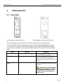
4 Initial Operation
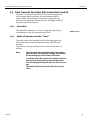
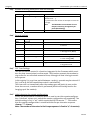
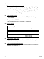
4.1 Front panel
INSYS Modem 56k small INT 2.0 INSYS Modem 56k small INT USB 1.0
The INSYS Modem 56k small INT has two LEDs to indicate the operating state:
The left LED (Power RX/TX) displays the condition of the operating voltage and a data
transmission. The right LED (OH/DCD) displays the status OH (off hook) and DCD (data
carrier detect). The exact meaning of the display elements is described in the following
table.
State Left LED Right LED
LED off No operating voltage applied.
The modem is not “off hook” (it has
not yet “lifted the receiver”).
LED is green Operating voltage applied. The modem is hooked to the phone
line (it has “lifted the receiver”); a
connections has not yet been estab-
lished.
LED is or blinks or-
ange
Data is transmitted. The connection to the remote ter-
minal is established, the carrier was
detected
If the DCD line at the modem is
permanently switched on, it cannot
be distinguished, whether a con-
nection to the remote terminal is
active or not.

INSYS Modem 56k small INT 2.0/USB 1.0 Initial Operation
June 06 9
LED is red The modem is not “off hook” (it has
not “lifted the receiver” yet) and the
DCD line at the modem is perma-
nently switched on.
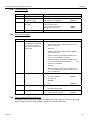
4.2 Top
Terminal Meaning
1 10..32V DC Power supply 10V - 32V DC
2 GND Ground
3 Reset Reset input
INSYS MICROELECTRONICS GmbH
Internet : www.insys-tec. de
Sales: insys@insys-tec.de
Support: support@insys-tec.de
GND
Reset
10...32 VDC
Power
supply
1
2
3
1
2
3
4 N/A
4.3 User Profiles
The modem offers a choice of profiles:
¾ Default factory setting:
The default factory settings enable you to achieve a fixed de-
fined basic state of the modem. Starting with this “basis”,
you can customize the modem according to your require-
ments.
¾ User profiles 0 and 1:
You can save configurations in the user profile, which may
be re-used for certain purposes.
A part of the S registry is saved in each profile. In the descrip-
tion, the affected registries are marked with an “*” in the S
registry.

Initial Operation INSYS Modem 56k small INT 2.0/USB 1.0
10 June 06
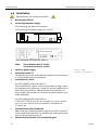
4.4 Installation
Please observe our safety instructions.
1. Mounting on DIN rail
2. Connecting the power supply
a) Connecting the ground connection
b) Connecting the power supply 10…32V DC
INSYS MICROELECTRONICS GmbH
Internet: www.insys-tec.de
Sales: insys@insys-tec.de
Support: support@insys-tec.de
GND
Reset
10...32 VDC
Power
supply
1
2
3
1
2
3
INSYS Modem 56k small INT 2.0
INSYS Modem 56k small INT USB 1.0
Note: The minimum value is 10V DC.
The maximum value is 32V DC.
3. Switch on power supply
4. Connection with a PC
Connect the 9-pin jack at the modem with the serial interface
or a USB interface of your computer.
5. Installation of a driver
For INSYS Modem 56k small INT 2.0:
The installation of a driver is not required when using a termi-
nal program or the HSComm. If you use another application, a
driver may be necessary. Please find our current drivers at
http://www.insys-tec.de/ or install the standard modem 336
under Windows.
For INSYS Modem 56k small USB 1.0:
If the INSYS USB drivers are not installed on your system
yet, you must perform the installation described in
Chapter 4.5 .
6. Communication with the Modem
Now, start your communication program on the PC and set it
to the used COM interface. The modem will automatically ad-
just to the baud rate of your PC.
7. Communication Control via a Terminal Program
Power LED
lights up green

INSYS Modem 56k small INT 2.0/USB 1.0 Initial Operation
June 06 11
Perform a short test using your terminal program.
(TeraTermPro, ProcommPlus).
Open the terminal program and enter
the command.
When the message appears on your monitor, the device has
been successfully installed.
8. Check the communication using the configuration program
HSComm
Open installed HSComm The configuration program will
automatically search for the connected modem
9. Connection to the telephone network
Connect the modem with the phone outlet, using the sup-
plied phone cord.
10. Connection Test
Perform a manual connection, either to another modem or, in
this example, to Freenet.
Dial the following number 0101901929
For PBXs that require a code number to establish
a connection - usually “0”- a different com-
mand must be used.
The modem will establish a connection
AT Enter
LED RXTX
lights up for
a short time
OK
ATDT 0101901929
ATX3DT 0,0101901929
LED OH lights up
Connect…

Initial Operation INSYS Modem 56k small INT 2.0/USB 1.0
12 June 06
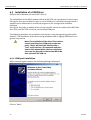
4.5 Installation of a USB Driver
(Only for INSYS Modem 56k small INT USB 1.0)
The installation of the INSYS modem 56k small INT USB 1.0 is performed in three steps.
During the first two installation steps, a virtual COM port is installed, through which a
modem can be addressed via a terminal program or the configuration software
HSComm.
During the third step, a modem driver can be installed, which can address the INSYS Mo-
dem 56 k small INT USB 1.0 at the just installed COM port.
The following describes the installation of the driver using the operating system Win-
dows XP. The installation of the driver using Windows 2000 is slightly different, but in
general very similar.
Note: The installation of the driver files creates a
virtual serial interface (COM port) on the com-
puter. The PC will treat this interface like a
"real" serial interface. All commands and func-
tions in this manual which relate to serial inter-
faces can also be used for the version INSYS Mo-
dem 56k small INT USB 1.0.
4.5.1 COM port installation
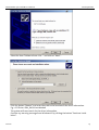
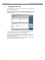
When connecting the modem, the following dialog is displayed:
Click on "Next"...

INSYS Modem 56k small INT 2.0/USB 1.0 Initial Operation
June 06 13
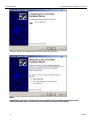
Select the item "Software from a list..." and click on "Next"...
Click the button "Browse" and enter the path to the location of the driver information.
E.g.: <CD Drive>\DIN_Rail\Driver\Modem
The system will now search for the driver information.
Confirm any warning message from Windows XP by clicking the button "Continue instal-
lation".

Initial Operation INSYS Modem 56k small INT 2.0/USB 1.0
14 June 06
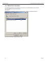
Click on "Finish" to complete the first part of the installation.
Note:
Immediately after the first driver has been installed, this installation route must be per-
formed the same way a second time to install the second part of the driver.

INSYS Modem 56k small INT 2.0/USB 1.0 Initial Operation
June 06 15
After the second installation has been completed, the system has a new COM port avail-
able. You can check the installation by opening the device manager in the start menu at
Control Panel ->System -> Hardware -> Device Manager
In this example, the modem was installed at
COM port 4. The modem can now only be ad-
dressed via this COM port, using the configura-
tion software HSComm, for example.
For many applications, the installation up to
this point is sufficient.
If the modem is supposed to appear as a mo-
dem in the control panel as well (e.g. to setup a
RDT - remote data transmission - connection),
you must install an additional modem driver to
ensure the functioning of the installed COM
port. The following Chapter will show the de-
tails.

Initial Operation INSYS Modem 56k small INT 2.0/USB 1.0
16 June 06
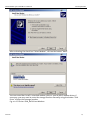
4.5.2 Modem Driver Installation
The following describes the installation of a driver for an INSYS Modem. Open the mo-
dem management in the control panel.
Start menu:
Control Panel ->Network and Internet Connections -> Phone and Modem Options
Start the installation using the button "Add".

INSYS Modem 56k small INT 2.0/USB 1.0 Initial Operation
June 06 17
After activating the check box "Select Modem", click on the button "Next".
You can now either install a standard modem 56k or a special INSYS modem driver. If
necessary, you may need to enter the storage location manually using the button "Disk
Drive" to select the storage location.
E.g. at: <CD Drive>\DIN_Rail\Driver\Modem

Initial Operation INSYS Modem 56k small INT 2.0/USB 1.0
18 June 06
Now enter the COM port for the modem connection. Use the virtual COM port that was
installed in the previous chapter. In our example, this is COM 4.
Click on "Next" to complete the installation.
The installation is completed.

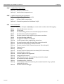
INSYS Modem 56k small INT 2.0/USB 1.0 Functions
June 06 19
5 Functions
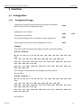
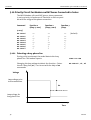
5.1 Configuration
5.1.1 Configuration Change
Loading the factory settings into the active profile will enable
you to easily recover an executable state.
Loading the user profile 0
Loading the user profile 1
Prior to the loading of the user profile, a reset is performed.
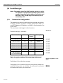
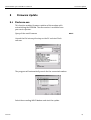
The settings of all profiles can be displayed in a chart.
Example:
The active profile will show all settings currently used by the modem.
ACTIVE PROFILE:
B3 E1 L1 M1 Q0 T V1 W0 X4 *A1 *L0 *M0 *P0 *R1 %B0 %C3 %E2
%S0
\A1 \N3 \V0 &A0 &C1 &D2 &G0 &K3 &Q5 &R1 &S0 &X0 &Y0
S00:005 S02:043 S06:003 S07:050 S08:002 S09:006 S10:014
S11:085 S12:050 S13:003
S15:000 S17:042 S18:000 S24:000 S36:135 S40:104 S41:195
S46:138 S95:000
Our example currently shows the settings from user profile 0.
User profile 0:
STORED PROFILE 0:
B3 E1 L1 M1 Q0 T V1 W0 X4 *A1 *L0 *M0 *P0 *R1 %B0 %C3 %E2
%S0
\A1 \N3 \V0 &A0 &C1 &D2 &G0 &K3 &Q5 &R1 &S0 &X0
S00:005 S02:043 S06:003 S07:050 S08:002 S09:006 S10:014
S11:085 S12:050 S13:003
S15:000 S17:042 S18:000 S24:000 S36:135 S40:104 S41:195
S46:138 S95:000
User profile 1:
AT&F
ATZ0 ATZ
ATZ1
AT&
V

Functions INSYS Modem 56k small INT 2.0/USB 1.0
20 June 06
STORED PROFILE 1:
B3 E1 L1 M1 Q0 T V1 W0 X4 *A1 *L0 *M0 *P0 *R1 %B0 %C3 %E2
%S0
\A1 \N3 \V0 &A0 &C1 &D2 &G0 &K3 &Q5 &R1 &S0 &X0
S00:005 S02:043 S06:003 S07:050 S08:002 S09:006 S10:014
S11:085 S12:050 S13:003
S15:000 S17:042 S18:000 S24:000 S36:135 S40:104 S41:195
S46:138 S95:000
Note: The user profiles 0 and 1 can be modified without affecting the active pro-
file.
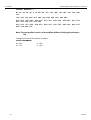
Storage location for the phone numbers:
TELEFONNUMMERN:
0= <Z0> 1= <Z1>
2= <Z2> 3= <Z3>
Page is loading ...
Page is loading ...
Page is loading ...
Page is loading ...
Page is loading ...
Page is loading ...
Page is loading ...
Page is loading ...
Page is loading ...
Page is loading ...
Page is loading ...
Page is loading ...
Page is loading ...
Page is loading ...
Page is loading ...
Page is loading ...
Page is loading ...
Page is loading ...
Page is loading ...
Page is loading ...
Page is loading ...
Page is loading ...
Page is loading ...
Page is loading ...
Page is loading ...
Page is loading ...
Page is loading ...
Page is loading ...
Page is loading ...
Page is loading ...
Page is loading ...
Page is loading ...
Page is loading ...
Page is loading ...
Page is loading ...
Page is loading ...
Page is loading ...
Page is loading ...
Page is loading ...
Page is loading ...
Page is loading ...
Page is loading ...
Page is loading ...
Page is loading ...
Page is loading ...
Page is loading ...
Page is loading ...
Page is loading ...
Page is loading ...
Page is loading ...
Page is loading ...
Page is loading ...
Page is loading ...
Page is loading ...
Page is loading ...
Page is loading ...
Page is loading ...
Page is loading ...
Page is loading ...
Page is loading ...
Page is loading ...
Page is loading ...
Page is loading ...
Page is loading ...
Page is loading ...
Page is loading ...
Page is loading ...
Page is loading ...
Page is loading ...
Page is loading ...
Page is loading ...
Page is loading ...
Page is loading ...
Page is loading ...
Page is loading ...
Page is loading ...
Page is loading ...
-
 1
1
-
 2
2
-
 3
3
-
 4
4
-
 5
5
-
 6
6
-
 7
7
-
 8
8
-
 9
9
-
 10
10
-
 11
11
-
 12
12
-
 13
13
-
 14
14
-
 15
15
-
 16
16
-
 17
17
-
 18
18
-
 19
19
-
 20
20
-
 21
21
-
 22
22
-
 23
23
-
 24
24
-
 25
25
-
 26
26
-
 27
27
-
 28
28
-
 29
29
-
 30
30
-
 31
31
-
 32
32
-
 33
33
-
 34
34
-
 35
35
-
 36
36
-
 37
37
-
 38
38
-
 39
39
-
 40
40
-
 41
41
-
 42
42
-
 43
43
-
 44
44
-
 45
45
-
 46
46
-
 47
47
-
 48
48
-
 49
49
-
 50
50
-
 51
51
-
 52
52
-
 53
53
-
 54
54
-
 55
55
-
 56
56
-
 57
57
-
 58
58
-
 59
59
-
 60
60
-
 61
61
-
 62
62
-
 63
63
-
 64
64
-
 65
65
-
 66
66
-
 67
67
-
 68
68
-
 69
69
-
 70
70
-
 71
71
-
 72
72
-
 73
73
-
 74
74
-
 75
75
-
 76
76
-
 77
77
-
 78
78
-
 79
79
-
 80
80
-
 81
81
-
 82
82
-
 83
83
-
 84
84
-
 85
85
-
 86
86
-
 87
87
-
 88
88
-
 89
89
-
 90
90
-
 91
91
-
 92
92
-
 93
93
-
 94
94
-
 95
95
-
 96
96
-
 97
97


Insys 11-02-01-01-43.003 User manual
- Category
- Modems
- Type
- User manual
- This manual is also suitable for
Ask a question and I''ll find the answer in the document
Finding information in a document is now easier with AI
Related papers
-
Insys Modem 56k 4.2 Owner's manual
-
-
-
-
-
-
-
-
-
Other documents
-
Aluratek AWUM100F User manual
-
Advantek Networks AEM-56K-LU Installation guide
-
Sitecom DC-009 Datasheet
-
Multi-Tech Systems Network Card MT2834ZDX User manual
-
Multitech MT2834ZDX User manual
-
Abocom UCM560 User manual
-
WTI MT5634/MT9234 Internal Modem User manual
-
 Western Telematic MT5634 User manual
-
MicroNet SP3006 User manual
-
Lucent Technologies H08-15328 Reference guide
