Page is loading ...

10 SUNNEN DRIVE, ST. LOUIS MO 63143
PHONE 314-781-2777, FAX 314-781-3636
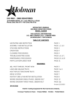
OPERATOR'S MANUAL
HOLMAN CONVEYOR BAKERS
MODEL MM14
FOR SERVICE INFORMATION
U. S. AND CANADA CALL: TOLL FREE 1-800-225-3958
TABLE OF CONTENTS
UNCRATING AND INSPECTION PAGE 1
ASSEMBLY AND INSTALLATION PAGE 1, 2, 3
STACKING INSTRUCTIONS PAGE 3
OPERATION PAGE 4
CLEANING PROCEDURES PAGE 4, 5
TROUBLESHOOTING GUIDE PAGE 5, 6, 7
MAINTENANCE PROCEDURES PAGE 8, 9, 10
PARTS LIST/EXPLODED VIEW PAGE 11
DRAWINGS
LOAD AND UNLOAD TRAYS PAGE 2
REMOVING THE CONVEYOR BELT PAGE 4
HEAT REFLECTOR/CRUMB TRAYS PAGE 6
HEATER TUBE & FAN MOTOR INSTALLATION PAGE 8
DRIVE SYSTEM PAGE 9
COMPONENT ARRANGEMENT PAGE 10
WIRING DIAGRAM PAGE 12
HEATER TUBE CHART PAGE 13
REVISED 06/18/04
U:\HOLMAN MANUALS\CURRENT MODELS\QUIZNO'S
HG0341

PAGE 1
OPERATOR'S MANUAL
HOLMAN CONVEYOR BAKERS
MODEL MM14
UNCRATING AND INSPECTION
Unpack unit and components from container. Remove all visible packing material, inspect unit for damage.
If damage is discovered, file a claim immediately with the carrier that handled the shipment.
The following should be included in the container:
A. 1ea. Baking oven with heaters, tunnel extender, power supply lead and conveyor belt in place.
(NOTE): Remove heating element shipping supports.
B. 1ea. Stainless Steel Unload Tray and 1ea. Stainless Steel Load Up Tray.
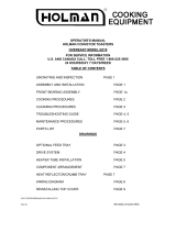
ASSEMBLY AND INSTALLATION
A. Attach legs by screwing into weld nuts, as shown
ADJUSTABLE LEGS SCREWS INTO
WELD NUT ON BOTTOM OF UNIT.
B. Anti Skid pads are available at no charge and may be adhered to the foot
section of each leg to prevent sliding. Call 1-800-225-3958 for details.
CAUTION: Use of these pads are not approved by the National Sanitation Foundation.
C. Install unit in its operating position. The load & unload ends must be at least 6" from any vertical
combustible surfaces. Allow sufficient space for operating personnel.
1. Your model MM14 conveyor oven is suppiled with a six foot power supply lead. Have an
electrician connect input power to the unit in accordance with local electrical codes.
ASSEMBLY AND INSTALLATION CONT. ON PAGE 2 REVISED 7/9/01 MJC

PAGE 2
OPERATOR'S MANUAL
HOLMAN CONVEYOR BAKERS
MODEL MM14
ASSEMBLY AND INSTALLATION (CONT)
WARNING:
MAKE SURE ALL INPUT POWER IS OFF BEFORE INSTALLING/REMOVING ANY PARTS.
WARNING:
BEFORE INSTALLING UNIT(S), HAVE YOUR ELECTRICIAN CHECK WITH LOCAL POWER
COMPANY TO DETERMINE ACTUAL VOLTAGE AT JOB SITE.
WARNING:
BE ABSOLUTELY SURE THE GROUND (EARTH) CONNECTION FOR THE RECEPTACLE IS
PROPERLY WIRED. NEVER CONNECT UNIT TO POWER WITHOUT PROPER GROUND CONNECTIONS.
IMPROPER GROUND MAY RESULT IN SEVERE INJURY OR FATALITY.
E. Before applying input power to the unit(s) check heating elements for breakage, do not apply power to
the unit(s) if a broken tube is found. If no broken tubes are found apply input power by switching the
master On/Off toggle to the ON position. Turn conveyor belt speed control to the maximum setting and
check all heater tubes and conveyor for proper operation.
F. Allow approximately 5 to 8 minutes for the fan cooling system to come on, check the air intake area as
noted below and be sure that there is a sufficient flow of air into the control box.
AIR INTAKE LOCATED
ON BOTTOM CONTROL
BOX COVER.
G. If all heaters and conveyor system are operating properly, switch the master on/off switch to the OFF
position and allow unit to cool. The fan will continue to circulate cool air through out the unit until the
internal temperatures have been decreased.
H. If a problem is discovered during start up procedures, immediately switch the Master On/Off switch to
the OFF position and notify a service agent in your area. Install load and unload trays as shown.
CRUMB TRAYCRUMB TRAY
LOAD UP
TRAY
UNLOAD TRAY
ASSEMBLY AND INSTALLATION CONT. ON PAGE 3
REVISED 7/9/01 MJC

PAGE 3
OPERATOR'S MANUAL
HOLMAN CONVEYOR BAKERS
MODEL MM14
ASSEMBLY AND INSTALLATION (CONT.)
F. Stacking Instructions
When stacking two Holman Proveyor ovens a stacking spacer with external air
duct must
be used to prevent overheating of the control box in the top oven.
1). If cart is to be used with units, place bottom unit on cart and align leg holes of unit
to holes in top portion of cart. Insert 3/8" bolts through cart and into leg holes to secure bottom unit
to cart as shown below.
2). Place stacking spacer on top of bottom oven with internal
air duct facing up and toward the rear of
the oven.
3). Mount external
air duct on stacking spacer as shown below. External air duct must be installed for
cooling system of top unit to function properly.
4). Screw cap screws (4ea.) into leg holes on top oven.
5). Place top oven on stacking spacer. Cap screws will set into cut outs in top of stacking spacer to
lock unit into position. (NOTE) Air intake of top unit must fit over the internal air duct of
stacking spacer to allow airflow into the control box of the top oven. For stacking spacer to
work properly, both ovens must have the same belt travel direction.
TOP UNIT - LEGS ARE
REPLACED WITH CAP SCREWS.
UNIT SITS ON TOP OF SPACER
STACKING SPACER (REQUIRED)
MOUNTS ON TOP OF LOWER OVEN
EXTERNAL AIR DUCT
MOUNTS ON SPACER
MOUNTING BOLTS FOR LOWER
UNIT SCREW INTO LEG HOLES
THROUGH CART
BOTTOM UNIT - CAN
BE COUNTER MOUNTED
OR PLACED ON A CART
A
S SHOWN.
REVISED 7/9/01MJC

PAGE 4
OPERATOR'S MANUAL
HOLMAN CONVEYOR BAKERS
MODEL MM14
OPERATION
A. Switch Master On/Off switch to the ON position and turn Variable Speed Control to fastest time setting.
B. Allow 10 to 15 minutes for unit(s) to warm up.
C. Adjust conveyor belt speed to the desired pass time and place product on conveyor belt.
CLEANING PROCEDURES
Preventive maintenance for your Holman oven consists of the following recommendecleaning
procedures. To keep your oven in its top operating condition, these steps should be performed daily or
weekly as indicated.
WARNING:
HIGH VOLTAGES ARE PRESENT IN THESE UNITS. DISCONNECT UNIT FROM POWER
SUPPLY BEFORE SERVICING OR CLEANING UNIT.
A. Remove Load and Unload Trays (daily) as shown and wash with hot soapy water.
CRUMB TRAYCRUMB TRAY
LOAD UP
TRAY
UNLOAD TRAY
B. Remove the Crumb Trays from both load and unload ends of the oven (daily) as shown above, (DO
NOT CLEAN WITH CAUSTIC CLEANERS ).
C. For lightly soiled conveyor surfaces a damp cloth or scotch pad can be used without removing the
conveyor belt. (daily)
D. For heavily soiled conveyor surfaces disconnect and remove the conveyor as shown and soak in hot
soapy water overnight (as required).
NOTE: LUBRICATION OF DRIVE CHAIN WITH A GRAPHITE BASED LUBRICANT IS REQUIRED AS
PERIODIC MAINTENANCE. CALL HOLMAN FACTORY SERVICE DEPARTMENT FOR DETAILS.
CLEANING PROCEDURES CONT. PAGE 5
REVISED 7/9/01 MJC

PAGE 5
OPERATOR'S MANUAL
HOLMAN CONVEYOR BAKERS
MODEL MM14
CLEANING PROCEDURES CONT.
E. Check Air Intake area for dust and grease. To clean, remove the Control Box Cover and wipe with a
dry cloth. Do not spray cleaning fluids into the Air Intake. This may result in component failure.
F. Re-assemble unit and check to be sure it is operating properly. Contact the Holman Cooking
Equipment Factory Service Team if assistance is required.
TROUBLESHOOTING GUIDE
A. UNIT WILL NOT HEAT, CONVEYOR BELT WILL NOT TURN.
1. Be sure main Circuit Breaker is switched to the ON position and there is power at the outlet.
2. Check to see that the unit is connected to power and Master On/Off is switched to the ON
position.
3. Be sure HEAT LIMIT SWITCH is pushed in (see below).
CUTAWAY VIEW OF CONTROL BOX WITHOUT
CONTROL BOX COVER.
HEAT LIMIT SWITCH LOCATED ON FRONT OF CONTROL BO
BENEATH FRONT EXTENSION.
B. UNIT WILL NOT HEAT, CONVEYOR TURNS.
1. Check to see if the Master On/Off Switch is in the on position.
2. Press Heat Limit Switch, located on the front section of the control box as shown above. If this
reactivates the Heater Tubes, see section C page 6.
3. Contact the Holman Cooking Equipment Factory Service Team if assistance is required.
TROUBLESHOOTING GUIDE CONT. ON PAGE 6
REVISED 7/9/01 MJC

PAGE 6
OPERATOR'S MANUAL
HOLMAN CONVEYOR BAKERS
MODEL MM14
TROUBLESHOOTING GUIDE CONT.
C. HEAT LIMIT SWITCH
Your Holman Conveyor Oven is equipped with an automatically activated HEAT LIMIT SWITCH which
interrupts the heater tube connections if the air temperature in the control box exceeds 190F (88C). This
Limit Switch can be reset manually by pushing the button in the center of the switch which is located as
shown.
HEAT LIMIT SWITCH
THE HEAT LIMIT SWITCH CAN BE ACTIVATED IF THERE IS NOT A PROPER AMOUNT OF AIR
FLOW BEING GENERATED BY THE COOLING FAN. IF THIS OCCURS:
1. DISCONNECT UNIT FROM POWER SOURCE.
2. Check to see if air intake area (openings in bottom center of Control Box) is free of dust, grease
or other obstructions.
3. Check to see if Crumb Trays (heat reflectors) are in place.
NEVER OPERATE UNIT WITHOUT CRUMB TRAYS IN POSITION AS THIS CAUSES
OVERHEATING IN THE CONTROL BOX.
CRUMB TRAYCRUMB TRAY
TROUBLESHOOTING GUIDE CONT. ON PAGE 7
REVISED 7/9/01 MJC

PAGE 7
OPERATOR'S MANUAL
HOLMAN CONVEYOR BAKERS
MODEL MM14
TROUBLESHOOTING GUIDE CONT.
D. CONVEYOR WILL NOT TURN, UNIT HEATS PROPERLY.
1. DISCONNECT UNIT FROM POWER SOURCE.
2. Check to see if there are obstructions in the conveyor system that may cause a jam.
3. Remove Air Intake Cover as shown on page 9 and spin the Drive Motor Shaft as shown on page
10. Recheck to see if the Conveyor now works.
IF CONVEYOR STILL DOES NOT TURN;
4. Remove power supply Side Panel and Drive Motor Sprocket (see below). Manually move
Conveyor Belt to check for mechanical binding. If Conveyor moves freely, call Holman Service
Department (1-800-225-3958) as Drive Motor and/or Variable Speed Control may have to be
replaced (refer to page 9 for instructions on replacing drive motor).
DRIVE CHAIN
DRIVE SPROCKET
DRIVEN SPROCKET
E. CONVEYOR TURNS AT ONE SPEED REGARDLESS OF SPEED
CONTROL SETTING.
1. Call Holman Service Department (1-800-225-3958) as Variable Speed Control may have to be
replaced. (refer to page 10 for instructions on replacing the Variable Speed Control).
F. COOLING FAN DOES NOT START.
1. Remove Control Box Cover and check Fan Blade for obstructions.
2. Check Fan Motor Cord for secure connection.
3. Call Holman Factory Service Team as the Fan Switch and/or Fan Motor may have to be
replaced.
REVISED 7/9/01 MJC

PAGE 8
OPERATOR'S MANUAL
HOLMAN CONVEYOR BAKERS
MODEL MM14
MAINTENANCE PROCEDURES
A. REPLACING HEATER TUBES (see below)
1. DISCONNECT UNIT FROM POWER SOURCE.
2. Remove left and right side panels by removing the philips head screws in each panel. Pull the top
of each panel out slightly and lift up.
3. Disconnect heater tube wires which require replacement from terminal block connections.
4. Remove Heater Tube Retainer by removing retainer screw with washer (retainers are located on
power supply side of unit).
5. GENTLY
, pull defective Heater Tube out of unit.
6. GENTLY
, place new Heater Tube into unit.
7. Replace heater tube retainers.
8. Reconnect heater wires to terminal block connections.
9. Replace side panels and test unit for proper operation
HEATER
TUBE RETAINERS
HEATER TUBE
SIDE PANEL
B. REPLACING FAN MOTOR
1. DISCONNECT UNIT FROM POWER SOURCE.
2. Remove control box cover with Fan Motor.
3. Unplug power supply cord from Fan Motor.
4. Remove(4)screws which hold Fan Motor and grill to cover.
5. Put replacement motor and grill in place and secure to the control box cover with screws.
6. Reconnect power supply cord to Fan Motor.
7. Replace control box cover.
FAN MOTOR
SECURED BY 4 SCREWS
AIR INTAKE
CONTROL BOX COVER
MAINTENANCE PROCEDURES CONT. PAGE 9
REVISED 7/9/01MJC

PAGE 9
OPERATOR'S MANUAL
HOLMAN CONVEYOR BAKERS
MODEL MM14
MAINTENANCE PROCEDURES CONT.
C. REPLACING BELT DRIVE MOTOR
1. DISCONNECT UNIT FROM POWER SOURCE.
2. Remove power supply side panel and control box cover as described in section B
in previous procedure.
3. Remove sprocket from motor shaft by loosening the
allen screw on the sprocket collar.
4. Disconnect the Drive Motor leads to the internal wiring. Motors are rated 208
Volts or 240 Volts, note which color leads are being used for these
connections and which lead is capped with white tape. The new Drive Motor
should use the same arrangement.
5. Remove the four screws that hold the Drive Motor in place.
6. Put the new motor in place and loosely attach with the four screws
removed from step 5.
7. Replace the Sprocket onto the motor shaft, then replace the Drive Chain onto the sprockets.
DRIVE SPROCKET WITH SET SCREW
DRIVE MOTOR
DRIVE MOTOR
MOUNTING SCREW
CUT AWAY VIEW OF DRIVE MOTOR
IN CONTROL BOX.
8. Slide the Drive Motor until the Drive Chain has about 1/8" slack when
lightly pushed at the center of its top open run. Tighten the Drive Motor
screws.
9. Rewire the Drive Motor as described in step 4 above. Replace the panels and test
for proper operation.
MAINTENANCE PROCEDURES CONT. PAGE 10
REVISED 7/9/01 MJC

PAGE 10
OPERATOR'S MANUAL
HOLMAN CONVEYOR BAKERS
MODEL MM14
MAINTENANCE PROCEDURES CONT.
D. REPLACING THE VARIABLE SPEED CONTROL (see below)
1. DISCONNECT UNIT FROM POWER SOURCE.
2. Remove two philips head screws holding control side panel in place and remove side panel.
3. Remove the Variable Speed Control knob and the lock nut holding the Variable
Speed Control in place.
4. Wires from Variable Speed Control go in to terminal block located on side of
chassis. Remove wires for old Variable Speed Control and insert wires for new
Variable Speed Control in same positions as shown on wiring diagram on page 12.
5. When replacing the Variable Speed Control in the side panel be sure to reposition
the anti-rotation pin in the anti-rotation slot on the panel.
6. Replace lock nut and control knob
FAN SWITCH
WASHER
NUT
NUT
KNOB
SWITCH
E. REPLACING HEAT CONTROLS
1. DISCONNECT UNIT FROM POWER SOURCE.
2. Remove two philips head screws holding control side pane in place and remove side panel.
3. Remove the Control Box Cover by removing the two screws and pulling
down and out to the front.
4. Remove the lock washers and nuts holding the mounting brackets in
place.
5. Place the new control into position and replace mounting nut and washer, exchange wires one
terminal at a time from the defective control to the replacement control.
6. Replace control box cover.
1). Contactor/Relay 2). Heat Limit Switch 3). Drive Motor 4). Terminal Strip
1
2
3
4
REVISED 7/9/01 MJC

PAGE 11
OPERATOR'S MANUAL
HOLMAN CONVEYOR BAKERS
MODEL MM14
PARTS LIST
1.
2.
3.
4.
6.
7.
8.
8.
8.
8.
9.
10.
11.
12.
13.
18.
20.
21.
14.
15.
16.
17.
25.
22.
27.
29.
30.
23.
24.
26.
24.
28.
5.
19.
21a.
No. Qty. PART No. DESCRIPTION No. Qty. PART No.
DESCRIPTION
1. 1 402163 Cover, Top 17. 1 200562 Grill Fan Motor
2. *
Heater
Tube
Refer To Page 13 18. 1 118060 Speed Control
3. 6 401232 Retainer, Heater tube 19. 1 200427 Pilot Light
4. 1 160008 Conveyor Belt 20. 1 200552 Rocker Switch
5. 1 100982 Tunnel Extender 21. 1 200711 Control Knob
6. 1 101253 Drive Shaft 21a. 1 200708 Cap, Control Knob
7. 1 101252 Idler Shaft 22. 1 402230 Control Side Panel (L-R)
8. 4 112262 Bearing 22. 1 402231 Control Side Panel (R-L)
9. 1 200509 Drive Motor (right to left) 23. 1 402156
Side Panel, Cord Side (L-R)
9A 1 200504 Drive Motor (left to right) 23. 1 402155 Side Panel, Cord Side (R-L)
10. 1 150023 Drive Chain 24. 2 100955 Crumb Tray
11. 1 115362 Driven Sprocket 25. 1 100957 Load Up Tray
12. 1 200650 Drive sprocket 26. 1 100978 Unload Tray
13. 2 200574 Fan Switch 27. 4 200716 Leg, 2 ½" Metal
14. 1 115146 Reset Switch 28. 1 200573 Contactor/Relay, 40 amp
15. 1 200561 Fan Motor 29. 2 401233 Heat Shutter, (prior to 899)
16. 1 401636 Control Box Cover 30. 2 401206 Cover, Extensions
REV. 7/9/01 MJC

PAGE 12
OPERATOR'S MANUAL
HOLMAN CONVEYOR BAKERS
MODEL MM14
WIRE DIAGRAM
REVISED 7/9/01 MJC

PAGE 13
OPERATOR'S MANUAL
HOLMAN CONVEYOR BAKERS
MODEL MM14
HEATER TUBE PART LIST
The serial number date code are the last four digits of the unit’s serial number. If assistance is needed to
determine he correct heater tube for your model, please call the Star/Holman Service Department at 1-800-807-
9054.
MODEL **S/N DATE
CODE
VOLTS PART NO. STYLE POSITION QTY
MM14 0199 TO 0899 208 GE-198002 QUARTZ TOP 6
MM14 0199 TO 0899 208 2N-209195
*METAL BOTTOM
6
MM14 0199 TO 0899 240 GE-198005 QUARTZ TOP 6
MM14 0199 TO 0899 240 2N-209196
*METAL BOTTOM
6
MODEL **S/N DATE
CODE
VOLTS PART NO. STYLE POSITION QTY
MM14 0999 TO 0701 208 GE-198010 QUARTZ TOP 6
MM14 0999 TO 0701 208 2N-209195
*METAL BOTTOM
6
MM14 0999 TO 0701 240 GE-198011 QUARTZ TOP 6
MM14 0999 TO 0701 240 2N-209196
*METAL BOTTOM
6
/