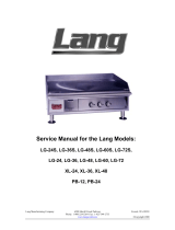
Lang C-28 User manual

Category
Thermostats
Type
User manual

This manual is also suitable for

Lang C-28 electric fryer is a versatile and high-performance kitchen appliance designed to make frying food easier, safer, and more efficient. With its durable stainless steel construction, user-friendly controls, and advanced safety features, the C-28 is ideal for both home and commercial kitchens.

Lang C-28 electric fryer is a versatile and high-performance kitchen appliance designed to make frying food easier, safer, and more efficient. With its durable stainless steel construction, user-friendly controls, and advanced safety features, the C-28 is ideal for both home and commercial kitchens.

Lang Manufacturing Company 6500 Merrill Creek Parkway Everett, WA 98203
Phone: 1-800-224-5264 Fax: 1-425-349-2733
www.langworld.com ©Copyright 2000
Service Manual for the Lang Models:
C-28, F-28
1
TABLE OF CONTENTS
CHAPTER PAGE
1. TABLE OF CONTENTS.......................................................................1
2. READ FIRST .......................................................................................2
3. EQUIPMENT DESCRIPTION..............................................................4
4. INSTALLATION...................................................................................5
5. START-UP...........................................................................................6
6. GENERAL OPERATION ..................................................................... 7
7. SEQUENCE OF OPERATION.............................................................8
8. TROUBLESHOOTING.........................................................................9
9. TECHNICAL DATA..............................................................................10
10. WIRING DIAGRAMS........................................................................... 11
11. PARTS LIST........................................................................................13
2
IMPORTANT READ FIRST IMPORTANT
CAUTION:
EACH UNIT IS HEAVY. FOR SAFE HANDLING,
INSTALLER SHOULD OBTAIN HELP AS NEEDED, OR
EMPLOY APPROPRIATE MATERIALS HANDLING
EQUIPMENT (SUCH AS A FORKLIFT, DOLLY, OR
PALLET JACK) TO REMOVE THE UNIT FROM THE SKID
AND MOVE IT TO THE PLACE OF INSTALLATION.
CAUTION:
ANY STAND, COUNTER OR OTHER DEVICE ON WHICH
FRYER WILL BE LOCATED MUST BE DESIGNED TO
SUPPORT THE WEIGHT OF THE FRYER.
CAUTION:
SHIPPING STRAPS ARE UNDER TENSION AND CAN
SNAP BACK WHEN CUT.
DANGER:
THIS APPLIANCE MUST BE GROUNDED AT THE
TERMINAL PROVIDED. FAILURE TO GROUND THE
APPLIANCE COULD RESULT IN ELECTROCUTION AND
DEATH.
WARNING:
INSTALLATION OF THE UNIT MUST BE DONE BY
PERSONNEL QUALIFIED TO WORK WITH ELECTRICITY.
IMPROPER INSTALLATION CAN CAUSE INJURY TO
PERSONNEL AND/OR DAMAGE TO EQUIPMENT. UNIT
MUST BE INSTALLED IN ACCORDANCE WITH ALL
APPLICABLE CODES.
NOTICE:
The data plate is located behind access door over tank
drain. The fryer voltage, wattage, serial number, wire
size, and clearance specifications are on the data plate.
This information should be carefully read and
understood before proceeding with the installation.
NOTICE:
The installation of any components such as a vent hood,
grease extractors, fire extinguisher systems, must
conform to their applicable National, State and locally
recognized installation standards.
NOTICE:
During the first few hours of operation you may notice a
small amount of smoke coming off the melter, and a faint
odor from the smoke. This is normal for a new melter
and will disappear after the first few hours of use.
CAUTION:
ALWAYS KEEP THE AREA NEAR THE APPLIANCE FREE
FROM COMBUSTIBLE MATERIALS.
CAUTION:
KEEP FLOOR IN FRONT OF EQUIPMENT CLEAN AND
DRY. IF SPILLS OCCUR, CLEAN IMMEDIATELY, TO
AVOID THE DANGER OF SLIPS OR FALLS.
3
IMPORTANT READ FIRST IMPORTANT
WARNING:
KEEP WATER AND SOLUTIONS OUT OF CONTROLS.
NEVER SPRAY OR HOSE CONTROL CONSOLE,
ELECTRICAL CONNECTIONS, ETC.
CAUTION:
MOST CLEANERS ARE HARMFUL TO THE SKIN, EYES,
MUCOUS MEMBRANES AND CLOTHING.
PRECAUTIONS SHOULD BE TAKEN TO WEAR RUBBER
GLOVES, GOGGLES OR FACE SHIELD AND
PROTECTIVE CLOTHING. CAREFULLY READ THE
WARNING AND FOLLOW THE DIRECTIONS ON THE
LABEL OF THE CLEANER TO BE USED.
NOTICE:
Service on this, or any other, LANG appliance must be
performed by qualified personnel only. Consult your
authorized service station directory or call the factory at
1-800-224-LANG (5264), or WWW.LANGWORLD.COM for
the service station nearest you.
WARNING:
BOTH HIGH AND LOW VOLTAGES ARE PRESENT
INSIDE THIS APPLIANCE WHEN THE UNIT IS
PLUGGED/WIRED INTO A LIVE RECEPTACLE. BEFORE
REPLACING ANY PARTS, DISCONNECT THE UNIT
FROM THE ELECTRIC POWER SUPPLY.
CAUTION:
USE OF ANY REPLACEMENT PARTS OTHER THAN
THOSE SUPPLIED BY LANG OR THEIR AUTHORIZED
DISTRIBUTORS CAN CAUSE BODILY INJURY TO THE
OPERATOR AND DAMAGE TO THE EQUIPMENT AND
WILL VOID ALL WARRANTIES.
4
EQUIPMENT DESCRIPTION
ELECTRIC FRYER
COUNTER MODEL
!
The fryer dimensions are 19” (48.25cm) High, 32” (81.25cm) Deep, 15” (38cm) wide.
!
The Sides, Bottom, and Rear wall are constructed stainless steel.
FLOOR MODELS
!
The interior dimension are 36” (91.5cm) High, 38” (96.5cm) Deep, 15” (38cm) wide.
!
The Sides, Bottom, and Rear wall are constructed stainless steel.
CONTROLS
!
Easy to use manual control knobs.
!
Indicator lights for “Power”, “Heat”, and “Over-temperature”.
!
The fryer is supplied with an auxiliary power interrupt terminal, which when connected,
automatically shuts off primary power to the fryer.
5
INSTALLATION
RECEIVING THE FRYER
Upon receipt, check for freight damage, both visible and concealed. Visible
damage should be noted on the freight bill at the time of delivery and signed by
the carrier's agent. Concealed loss or damage means loss or damage, which
does not become apparent until the merchandise has been unpacked.
If concealed loss or damage is discovered upon unpacking, make a written request for
inspection by the carrier's agent within 15 days of delivery. All packing material should be
kept for inspection.
Do not return damaged merchandise to Lang Manufacturing Company. File
your claim with the carrier.
Prior to un-crating, move the fryer as near its intended location as practical.
The crating will help protect the unit from the physical damage normally
associated with moving it through hallways and doorways.
ELECTRICAL CONNECTION
Electrical service may be made through a standard 1¼ inch conduit. A hole is provided
through the rear panel.
A knockout is also provided in the bottom rear of the fryer, so that power may be brought in
from below the unit.
Plug the hole on the rear panel when using bottom power entry.
Check the National Electrical Code for fuse for circuit breaker requirements.
A two pole terminal block is provided behind the rear access cover for connection to an
external fire control system if required. A jumper is provided across these terminals when the
fryer leaves the factory. The jumper on this terminal block is in series with the contactor coil
circuits. If connection to a fire control system is required, remove this jumper and supply a
relay contact closure to maintain this closed circuit. If the fire control system does not have
this type output, a separate relay must be provided to interface the system. Use copper wire
only.
CAUTIOIN: DO NOT APPLY POWER TO THESE TERMINAL.
EXTERNAL POWER WILL DAMAGE THE FRYER
CONTROL CIRCUITRY.
Connect a ground lead to the green ground lug provided in the rear compartment.
These fryers are to be connected to three-phase power as follows:
Connect wires 1 and 4 to line 1, wires 2 and 5 to line 2, and wires 3 and 6 to line 3.
Please contact the factory for single-phase connections.
CAUTION: DO NOT CONNECT TO A CIRCUIT OPERATING AT
MORE THAN 150 VOLTS TO GROUND.
PHASING
POWER
SUPPLY
TERMINAL
BLOCK
RANGE
TOP
L1 1,4
L2 2,5
THREE
PHASE
L3 3,6
6
START-UPS
C-28, F-28
Electric Fryer Start-Up
1.
Verify correct phasing of unit.
2.
Verify connections at plug and terminal block.
3.
Incoming Voltage: Single Phase L1-L2_____
Three Phase L1-L2_____ L2-L3_____ L3-L1_____
4.
Verify amperage. L1_____ L2_____ L3_____
Model #_______ Date_______ Serial #________
Store #___________ Tech Name___________________
Contact_______________ Company _________________________
Store Phone #___________ Service Company Phone #______________
Address_____________________
______________________
______________________
7
GENERAL
GENERAL OPERATION
Fill the fryer with cooking oil. There are two fill marks on the sides of the kettle. The oil level should be
maintained between the upper and lower marks.
The power switch on the control box at the front of the fryer energizes the control circuits. When this
switch is on, the “power” pilot lamp will be illuminated.
Turn the temperature selector dial on the thermostat to the desired temperature setting. This control is
located above the elements at the rear of the kettle. The “heat” pilot lamp will illuminate indicating power
is applied to the heating elements.
The lamp marked “overtemp” will illuminate if the oil reaches an over temperature condition. The over
temperature thermostat shuts off the fryer before the oil reaches a dangerously high temperature.
The elements may be raised and locked in the up position. The latch is located on the rear top surface of
the fryer and may be activated by lifting the handle at either side of the fryer.
A drain valve is provided at the left front of the fryer. Always turn the fryer power off before lifting the
elements of draining the oil from the fryer.
On those models with automatic bracket lifts, the cooking times may be set from 1 to 16 minutes with the
timer control dials.
Pressing down on the spring return elevator switches will lower the basket lifts. At the end of the time set
on the dial the lift will return to the up position. The time cycle may be canceled at any time by pressing
the elevator switch to the up position.
CONTROLS
Power Switch
- A toggle switch used to turn the unit on and off.
Pilot Lights
- Lights that are located in the rear control panel area.
Power
: Lights up when the power switch is in the “ON” position.
Heat
: Lights up when the element contactors engage.
Over-temp
: Lights up when the over-temperature thermostat trips.
Test Switch
- Optional on all models, it gives the user the ability to test the over-temperature thermostat
by overriding the thermostat and allowing the oil to exceed normal operating
temperatures.
8
SEQUENCE OF OPERATION
ELECTRIC FRYER
Power switch to “ON” position.
208/240 VAC to “
POWER
” pilot lamp.
208/240 VAC to Thermostat through Over-Temperature thermostat.
Thermostat Set.
208/240 VAC to “
HEAT
” pilot lamp.
208/240 VAC to Contactors.
Contactors Energize.
208/240 VAC to Elements.
Elements Energize.
Fryer heats up.
9
TROUBLESHOOTING
Will not heat
PROBABLE CAUSE CORRECTIVE ACTION
Incorrect voltage
!
Confirm that correct voltage is coming to unit.
!
Confirm that unit is phased correctly.
Defective Fuses
!
Confirm that fuses have 208/240 VAC to it.
!
Check fuses for proper operation.
Defective Power Switch
!
Confirm that switch has 208/240 VAC to it.
!
Check switch for proper operation.
Defective Over temperature
thermostat
!
Confirm that thermostat has 208/240 VAC to it.
!
Confirm that over temperature thermostat is closed and working
properly.
Defective Thermostat
!
Confirm that thermostat has 208/240 VAC to it.
!
Check that thermostat is operating properly.
Defective Contactor
!
Confirm that contactor has 208/240 VAC to it.
!
Check contactor for normal operation. (554
)
Defective Element
!
Confirm that elements are wired correctly.
!
Confirm that element has 208/240 VAC to it.
!
Confirm that there are no broken wires to the elements.
!
Check Element for continuity.
Overheating
PROBABLE CAUSE CORRECTIVE ACTION
Bulb out of Placement
!
Confirm that bulb is centered in element.
!
Confirm that bulb is secured in clips.
Oil level to Low
!
Confirm that oil levels are at proper level.
Sticking contactor
!
Confirm that points are not pitted.
!
Replace if necessary.
Food Stuck between Element
and bulb.
!
Remove food between element.
10
TECHNICAL DATA
ELEMENT RESISTANCE
Part Number Voltage Amps Resistance
!
11110-43 208 Volts 19
10.6
!
11110-41 240 Volts 7.6
29.6
!
11110-39 480 Volts 8
56.6
!
11110-46 415 Volts 9.5
40.1
!
11110-45 380 Volts 10.5
35.6
CONTACTOR RESISTANCE
Part # Voltage Coil
30700-05 208/240 Volts
554
TRANSFORMER RESISTANCE
Part # Primary Resistance Secondary Resistance
31400-04 480 Volts
66
240 Volts
16
FRYER LINE AMPERAGE, AND WATTAGE
ALL SERIES 28 ELECTRIC FRYERS
NOMINAL AMPS PER LINE
THREE PHASE
LOADING
THREE PHASE SINGLE PHASE
K.W. PER PHASE
Total
K.W.
208 VOLTS 240 VOLTS 480 VOLTS 208V 240V
Model
#
L1-L2L2-L3L3-L1 L1L2L3L1L2L3L1L2L3
-28 4.0 4.0 4.0 12.0 33.3 33.3 33.3 28.9 28.9 28.9 14.4 14.4 14.4
See
Factory
See
Factory
11
WIRING DIAGRAM 208/240
12
WIRING DIAGRAM 480
13
C-28
ELECTRIC FRYER
DESCRIPTION
PART NO.
Element C28 Fryer 480 Volt 4000 Watts 11110-39
Element C28 Fryer 208 Volt 4000 Watts 11110-43
Element C28 Fryer 240 Volt 4000 Watts 11110-44
Element C28 Fryer 380 Volt 4000 Watts 11110-45
Motor Lift Assembly 30200-02
Switch Micro Lift 30301-01
Switch Toggle Lift 30303-02
Switch Toggle On-Off 30303-06
Switch Toggle On-Off Metal Handle (Marine Only) 30303-11
Boot Threaded for Metal Toggle Switch 30303-15
Switch Temperature Control 12 Position 180-400°F (Remote Control Units
Only)
30304-18
Thermostat Safety 450°F Open (Remote Control Units Only)
30401-13
Thermostat Safety 425°F Open (Marine Only)
30401-19
Thermostat Over-Temp. Modification Kit 60101-26
Thermostat 400°F Fryer
30402-12
Terminal Strip 2 Pole 30500-01
Terminal Block 2 Pole 30500-08
Terminal Strip 3 Pole 30501-02
Relay 24 VDC 30600-01
Contactor 3 Pole 208/240 VAC 30700-05
Contactor 3 Pole 24 VAC (Remote Control Units Only) 30700-06
Fuse 15 Amp 30900-01
Fuse 15 Amp 300 Volt (Remote Control Units Only) 30900-10
Fuse 3 Amp 30900-15
Fuse Holder 15 Amp 30901-02
Fuse Holder 15 Amp (Remote Control Units Only) 30901-08
Transformer 480/240 VAC 31400-04
Transformer 240/24 VAC 31400-10
Transformer 480/24 VAC (Remote Control Units Only) 31400-15
Transformer 380/240 VAC 31400-17
Pilot Light 208/240V 6” Lead Black Body 31601-01
Pilot Light 480V 6” Lead Black Body 31601-02
Pilot Light 28 VAC (Remote Control Units Only) 31601-07
Circuit Breaker 480 Volt 2/10Amp 2 Pole (Marine Only) 31800-07
Circuit Board Assembly Timer 40100-07
Circuit Board Assembly Timer Mother 40100-08
Circuit Board Temperature Control (Remote Control Units Only) 40101-19
Potentiometer Timer 40900-06
Probe Temperature Sensor (Remote Control Units Only) 41100-23
Grab Bar Assembly 15” (Marine Units) 50300-49
Lift Rod 50800-09
Lift Rod Top 50800-18
Basket Hanger Assembly Non-Lift 51100-02
Basket Hanger Assembly Lift 51100-03
Drain Elbow Assembly 51100-16
Lift Handle 60102-21
Lower Element Clip 60102-31
Bottom Element Clamp 60102-32
14
C-28
ELECTRIC FRYER
DESCRIPTION
PART NO.
Element Clamp 60102-321
Upper Element Clip 60102-78
Thermostat Capillary Tube Spacer 60102-79
Capillary Tube Spacer 60102-80
Small Capillary Tube Clip 60102-81
High Limit Thermostat Spacer 60102-82
Bucket Fryer 60102-800
Panel Label C28 60301-16
Panel Label C28L 60301-18
Panel Label (Remote Control Units Only) 60301-103
Quick Disconnect Coupler 1” 70100-01
Quick Disconnect Nipple 1” 70100-02
Rulon Bearing for Basket Lift 70200-02
Valve Manual Drain 70400-01
Knob Temperature Control 70701-06
Knob Timer 70701-08
Knob Time Control (Remote Control Units Only) 70701-27
Plastic Capillary Tube Bushing 70801-05
Cap Drain Plug 70900-01
Roll Pin 1/4” X 1 71800-02
  • Page 1 1
  • Page 2 2
  • Page 3 3
  • Page 4 4
  • Page 5 5
  • Page 6 6
  • Page 7 7
  • Page 8 8
  • Page 9 9
  • Page 10 10
  • Page 11 11
  • Page 12 12
  • Page 13 13
  • Page 14 14
  • Page 15 15

Lang C-28 User manual

Category
Thermostats
Type
User manual
This manual is also suitable for

Lang C-28 electric fryer is a versatile and high-performance kitchen appliance designed to make frying food easier, safer, and more efficient. With its durable stainless steel construction, user-friendly controls, and advanced safety features, the C-28 is ideal for both home and commercial kitchens.

Ask a question and I''ll find the answer in the document

Finding information in a document is now easier with AI