– 1 –
Quick Start Guide
1. Unpack the Switch and Check Contents
SC30010
SC30020
SC30030
SC30040
SC30050
SC30060
Rack Mounting Kit—two brackets and eight screws
Four adhesive foot pads
Power Cord—either Japan, US, Continental Europe
or UK
Documentation—Quick Start Guide (this document),
Warranty Card and Safety and Regulatory
Information
Note: The C-300 series switches are for indoor use
only.
Note: For Safety and Regulatory information, refer to
the Safety and Regulatory Information document
included with the switch.
Note: Other documentation, including the Installation
Guide, Web Management Guide, and CLI Reference
Guide, can be obtained from www.signamax.com.
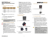
2. Mount the Switch
Attach the brackets to the switch.
Use the screws and cage nuts supplied with the rack to
secure the switch in the rack.
2
1
1
2
Caution:
Installing the switch in a rack requires two
people. One person should position the switch in the
rack, while the other secures it using the rack screws.
Note:
The switch can also be installed on a desktop or
shelf using the included adhesive rubber foot pads.
3. Ground the Switch
Ensure the rack on which the switch is to be mounted is
properly grounded and in compliance with ETSI ETS 300
253. Verify that there is a good electrical connection to
the grounding point on the rack (no paint or isolating
surface treatment).
Attach a lug (not provided) to a #12 AWG (PoE switch) or
#18 AWG (non-PoE switch) minimum grounding wire
(not provided), and connect it to the grounding point on
the switch rear panel. Then connect the other end of the
wire to rack ground.
Caution: The earth connection must not be removed
unless all supply connections have been
disconnected.
Caution: The device must be installed in a restricted-
access location. It should have a separate protective
earthing terminal on the chassis that must be
permanently connected to earth to adequately ground
the chassis and protect the operator from electrical
hazards.
1
2
1
2
E102017-AP-R01
150200001850Awww.signamax.com
C-300 Series Gigabit Managed Switch
Quick Start Guide
– 2 –
4. Connect Power
Plug the AC power cord into the socket on the rear of the
switch.
Connect the other end of the power cord to an AC power
source. Verify that the external AC power requirements
for the switch can be met as listed below:
SC30010: 100-240 VAC, 50/60 Hz, 1 A
SC30020: 100-240 VAC, 50-60 Hz, 5.8 A
SC30030: 100-240 VAC, 50-60 Hz, 3.2 A
SC30040: 100-240 VAC, 50-60 Hz, 0.5 A
SC30050: 100-240 VAC, 50-60 Hz, 2.1 A
SC30060: 100-240 VAC, 50-60 Hz, 0.5 A
Warning: For the SC30050, the bottom of the
enclosure is a hot surface. Do not touch!
Note:
For International use, you may need to change the
AC line cord. You must use a line cord set that has been
approved for the socket type in your country.
5. Verify Switch Operation
Verify basic switch operation by checking the system
LEDs.
When operating normally, the Power and Diag LEDs
should be on green.
1
1
2
1
6. Connect to the Web User Interface
Connect a PC to the switch through one of the RJ-45
ports.
The switch has a default management IP address of
192.168.2.10 and a subnet mask of 255.255.255.0. You
must set your PC IP address to be on the same subnet
as the switch (that is, the PC and switch addresses must
both start with 192.168.2.x).
Log in to the web interface or CLI using the default
settings: username “admin” and password “admin.”
Note:
For further information on switch configuration,
refer to the Web Management Guide and CLI Reference
Guide.
7. Connect Network Cables
For RJ-45 ports, connect 100-ohm Category 5, 5e or
better twisted-pair cable.
For the SFP/SFP+ slots, first install SFP/SFP+
transceivers and then connect fiber optic cabling to the
transceiver ports. The following transceivers are
supported:
1000BASE-SX (065-79SXMG)
1000BASE-LX (065-79LXMG)
1000BASE-ZX (065-79ZXMG)
1000BASE-LHX (065-79LXEDMG)
As connections are made, check the port status LEDs to
be sure the links are valid. Press the Mode button to
change from Ethernet to PoE status:
On/Blinking Green — Port has a valid link.
Blinking indicates network activity.
On Amber — Port is supplying PoE power.
1
2
3
2
1
1
2
3
www.signamax.com
Quick Start Guide
– 3 –
Hardware Specifications
8. Hardware Stacking Connection (Optional)
Install the SC30020 in a standard 19-inch rack and power
on.
Install the AP50010 chassis in a standard 19-inch rack.
Install one or more AP50020 PSUs in the chassis. The
chassis can support up to three AP50020 PSUs.
Use the PSU cable (provided) to connect each AP50020
PSU to an SC30020 switch.
Connect the AC power cord to power on the AP50020
PSU, and check the LEDs on the PSUs to ensure proper
operation. The Link LEDs for connected switches should
light up.
Switch Chassis
Size
(W x D x H)
SC30010/SC30020/SC30030/SC30040:
44 x 22 x 4.4 cm (17.32 x 8.66 x 1.73 in. )
SC30050:
33.0 x 20.4 x 4.26 cm (12.99 x 8.03 x 1.67 in.)
SC30060:
19.64 x 11.7 x 3.66 cm (7.73 x 4.61 x 1.44 in.)
Weight SC30010: 2.5 kg (5.5 lb)
SC30020: 3.1 kg (6.85 lb)
SC30030: 2.8 kg (6.18 lb)
SC30040: 2.2 kg (4.86 lb)
SC30050: 2.4 kg (5.34 lb)
SC30060: 816 g (1.8 lb)
Temperature Operating: 0°C to 50°C (32°F to 122°F)
Operating: 0°C to 45°C (32°F to 113°F), for
SC30020 only
Operating: 0°C to 40°C (32°F to 104°F), for
SC30050, and SC30020 with one AP50020
only
Storage: -40°C to 70°C (-40°F to 158°F)
Humidity Operating: 10% to 90% (non-condensing)
1
2
3
4
5
Power Specification
AC Input Power SC30010: 100-240 VAC, 50/60 Hz, 1 A
SC30020: 100-240 VAC, 50-60 Hz, 5.8 A
SC30030: 100-240 VAC, 50-60 Hz, 3.2 A
SC30040: 100-240 VAC, 50-60 Hz, 0.5 A
SC30050: 100-240 VAC, 50-60 Hz, 2.1 A
SC30060: 100-240 VAC, 50-60 Hz, 0.5 A
To tal Po w e r
Consumption
SC30010: 40 W
SC30020: 490 W
SC30020 with one AP50020: 950 W
SC30030: 260 W
SC30040: 20 W
SC30050: 160 W
SC30060: 8 W
Regulatory Compliances
Emissions CE Mark
EN 55022, Class A
FCC Class A
Immunity IEC 61000-3-3, 61000-4-2/3/4/5/6/11
www.signamax.com
  • Page 1 1
  • Page 2 2
  • Page 3 3

Ask a question and I''ll find the answer in the document

Finding information in a document is now easier with AI