newport-scientific.com
P 301-498-6700
F 301-490-2313
email [email protected]
Newport Scientific, Inc
8246E Sandy Court
Jessup, MD 20785-9632
USA
Portable Dew Point Monitor
for Compressed Air Desiccant Dryers
Model 8075A

8075A_B.docx February 2017

8075A_B.docx February 2017
Contents
Specifications ............................................................................... 1
Product Overview ........................................................................ 2
Features and Accessories ........................................................ 3
Operation .................................................................................... 5
Sample Connection Requirements .......................................... 5
Power Connection ................................................................... 6
Dryer Testing ........................................................................... 6
Remote Monitoring/Data Logging ........................................... 8
Maintenance and Adjustments ................................................... 9
Sample Hose Replacement ...................................................... 9
Filter Replacement .................................................................. 9
Monitor Disassembly ............................................................. 10
Sensor Replacement .............................................................. 11
Backpressure Orifice Inspection ............................................ 12
Display Units & Alarm Set Point Adjust ................................. 13
Troubleshooting ........................................................................ 15
Spare Parts & Accessories ......................................................... 18
Notes ......................................................................................... 19
Warranty .................................................................................... 20

8075A_B.docx 1 February 2017
Specifications
DEW POINT RANGE
-40F to +15F (-40C to -9C)
TYPICAL ACCURACY
±3F (±1.7C)
USABLE PRESSURE RANGE
20psig to 150psig
COMPRESSED AIR
CONSUMPTION
< 5SCFH
ALARM SET POINT
-10F (-23C)
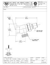
SAMPLE AIR CONNECTION
Industrial interchange
coupling set with 1/4” NPT
male threads
SENSOR PART NUMBER
1205DM
ANALOG OUTPUT SCALING
-40F to +70F (-40C to -9C)
ANALOG OUTPUT PORT
3 pin M8 male jack
POWER REQUIREMENTS
115VAC 50/60HZ
0.15A max
(230VAC optional)
DIMENSIONS
10.75” X 9.75” X 4.75”
NET WEIGHT
5.7lbs

8075A_B.docx 2 February 2017
Product Overview
The 8075A dew point monitor is used to check the function of a
desiccant dryer in a compressed air system. The monitor uses
an internal bleed orifice to continuously sample a small amount
of process air. The internal sensor is exposed to the line
pressure of the compressed air system and therefore reads
actual pressure dew point. Real-time dew point is displayed on
a large numeric LED display.
The monitor samples process air through six feet of flexible
hose which terminates in a standard 1/4” industrial quick
connect plug. This allows quick and easy testing of air wherever
a compatible quick connect is installed in the air distribution
piping. Just plug in the sample hose and wait for a dew point
reading.
In addition to the numeric LED display, the monitor includes
dew point condition indicator lights, and audible alarm, and a
linear signal output.

8075A_B.docx 3 February 2017
Features and Accessories
The dew point monitor and its accessories are housed in a
portable carrying case. Before using the monitor, familiarize
yourself with the features shown below:

8075A_B.docx 4 February 2017
POWER SWITCH
Turns monitor ON and OFF.
ALARM SWITCH
Enables local audible alarm when dew point
exceeds the alarm set point.
LINE CORD
Provides connection to power.
BEEPER (not
visible in picture)
Provides audible signal when the measured
dew point is above the alarm set point.
DEW POINT
CONDITION
INDICATORS
Green light is on when dry air is detected,
red light is on when measured dew point is
above the alarm set point.
LINE PRESSURE
GAUGE
Indicates actual air pressure at the sensor
housing inside the monitor.
SAMPLE HOSE
ASSEMBLY
Six feet of pressure resistant hose connects
monitor input port to compressed air test
location.
FILTER
Filter removes particulates from sample air.
HOSE STORAGE
CLIP
Secures sample hose when not in use.
QUICK CONNECT
1/4” industrial quick connect to install in
compressed air piping.
ANALOG OUT
4-20mA and 0-5V output for remote
monitoring or data logging. Mates with
standard 3 pin M8 female cable.
NOTE: The 8075A is shipped with a paper desiccant pack
which can be discarded when the unit is unpacked.

8075A_B.docx 5 February 2017
Operation
The 8075A is designed to sample compressed air. If you are
attempting to monitor air at atmospheric pressure, you need a
vacuum assisted monitor, consult the factory for other model
options.
CAUTION: The carrying case is not heat resistant. It may melt
or distort if left resting on the hot parts of a heated dryer. If a
surface is too hot to touch, it is too hot for the monitor!
Sample Connection Requirements
The 8075A is supplied with a 1/4” industrial interchange style
quick connect plug attached to 6 feet of sample hose. This plug
is compatible with many shop air quick connect sockets,
although a compatible socket is supplied with the monitor
which can be used as a dedicated test port in your compressed
air distribution line.
For best results, select a sample point that is close to the dryer
output. Avoid sampling at remote locations in your air
distribution system. Sections of air distribution piping which
serve little-used tools or terminate with a dead-end are not
good sampling points. The air in such lines can be stagnant and
won’t represent the actual condition of air that the dryer is
producing.
NOTE: sampled air should be free of debris and oil mist.
Particulates can clog the air bleed orifice and oil will damage
the sensor. Also, the air should not be saturated with water!

8075A_B.docx 6 February 2017
If air lines are wet, don’t connect the 8075A or sensor damage
might occur.
Power Connection
The 8075A is supplied with a 6 foot line cord for connection to
power. Always connect the monitor to the correct supply
voltage. Do not attempt to replace the line cord with a different
plug type to accommodate other supply voltages. The 8075A
will be damaged if connected to incorrect supply voltage.
Dryer Testing
CAUTION: Inspect the sample hose assembly before
connecting the monitor to a source of compressed air. If the
hose fittings are loose or there are signs of hose damage
(bulging, surface cuts, or frayed fibers) DO NOT use the
monitor until the hose is replaced!
Connect the 8075A sample hose plug to a compatible quick
connect socket in your air distribution line. The monitor will
begin to bleed air from the line as soon as it’s connected. Make
sure the pressure gauge on the monitor agrees with the line
pressure in your air system. If the monitor gauge reads
significantly lower than your actual air pressure, this might
indicate a plugged sample air filter. This pressure drop will
affect the accuracy of the monitor!
Turn on the 8075A and allow the reading to stabilize. The initial
reading will be +15F (-9C) until all the ambient air is purged
from the monitor’s tubing and internal fittings. After a few
minutes, the reading should start to drop until a stable reading
is obtained. It can take 30 minutes or more for the unit to

8075A_B.docx 7 February 2017
stabilize when first turned on.
NOTE: Not all dryers produce a -40F dew point. Check with
your dryer manufacturer for expected dew point levels.
Leave the 8075A connected and turned on to continuously
monitor dryer conditions. The built in red light and audible
beeper will indicate dryer trouble within moments of a dew
point rise.
A constantly high reading on the 8075A may indicate a
malfunctioning dryer.
NOTE: When storing the 8075A, carefully coil the sample hose
and snap the crimped metal ferrule into the storage clip. This
will prevent kinks from forming in the hose when the lid is
closed.

8075A_B.docx 8 February 2017
Remote Monitoring/Data Logging
The 8075A analog output jack can be used to monitor or log
dew point over a period of time.
The output jack is a 3 pin male M8 type connector. This
connector accepts standard threaded or snap fit female M8
cables.
Pin No.
Wire Color*
Signal
1
Brown
4-20mA (current sourcing)
3
Blue
Ground
4
Black
0-5V
* standard wire color code of M8 cable assemblies
Note that the output scaling is -40F to +70F.
1
3
4
Connector pinout
(front view)

8075A_B.docx 9 February 2017
Maintenance and Adjustments
Newport Scientific offers a maintenance and calibration service
for the 8075A. This service should be performed annually.
Alternatively, most wearable parts can be replaced by the user.
Sample Hose Replacement
A contaminated sample hose will slow down the response time
of the monitor. Also, worn or damaged hose is a safety hazard
and should be replaced when needed.
Use a pair of wrenches to unthread the hose fitting from the air
filter located at the monitor’s sample air inlet port. Remove all
remnants of thread sealing tape, any pieces left can get loose
during re-assembly could clog the internal bleed orifice. Apply
new tape to the filter threads and install hose.
Filter Replacement
If the pressure gauge on the 8075A
indicates lower than the actual line
pressure of the process air, a partially
clogged air filter might be the cause.
Remove the sample hose to access the
filter. With the filter removed, clean or
replace as needed. Remove all
remnants of thread sealing tape, any
pieces left can get loose during re-
assembly could clog the internal bleed
orifice. Observe the arrow direction
marked on the filter body.

8075A_B.docx 10 February 2017
Monitor Disassembly
To access the serviceable parts inside the monitor, the 8075A
panel must be removed from the carrying case.
WARNING: Unplug the 8075A from power before disassembly.
Even with the power switch off, voltages are present inside the
unit.
Use a screwdriver to remove the 5 screws along the perimeter
of the panel holding it in the case. Grab the sample air inlet
elbow to help lift the panel straight up and out of the case.
When re-assembling the panel into the case, make sure sensor
cable wires are tucked in and not pinched under the panel as
you lower it into the case.
Install the 5 mounting screws, taking care not to cross thread
the screws as you proceed. The screws only need to be snug to
the panel, do not overtighten!

8075A_B.docx 11 February 2017
Sensor Replacement
The internal sensor should be replaced on a yearly basis. It is
difficult to verify the accuracy of the sensor in the field. For
most users, an annual sensor
replacement can assure good
operation of the monitor. It is
recommended to clean the sample
tubing whenever the sensor is
replaced.
With the panel removed from the
case, locate the sensor housing and
pull the sensor cable connector
from the housing. The cable will
unplug straight out.
Unscrew the hex nut from the top of the sensor housing. With
the hex nut unscrewed, remove the sensor and insert along
with gasket. The sensor
will then unplug from the
insert. Replace sensor
and inspect gasket for
damage. Reassemble all
parts, hand tighten the
hex nut, and plug in the
sensor cable connector.

8075A_B.docx 12 February 2017
Backpressure Orifice Inspection
Refer to the Sensor Replacement section to locate the
backpressure orifice. Remove the clear tubing from the orifice
barbed end. Then use a pair of wrenches to unscrew the orifice
(avoid torqueing the pressure gauge mounting).
Hold the fitting up to a light, you should be able to see light
coming through the tiny hole in the orifice.
If no light is visible, try blowing compressed air through the
barbed side of the fitting to flush out any debris. If that doesn’t
clear it, a thin wire can be used to poke through the fitting. The
hole size is 0.017”, so avoid enlarging the hole with too large a
wire size.
When clean, replace fitting and re-connect the clear tubing onto
the barbed end.

8075A_B.docx 13 February 2017
Display Units & Alarm Set Point Adjust
The 8075A is factory set to
display dew point in F. The
display can be changed to
C by jumper configuration.
With the 8075A panel
removed from the carrying
case, locate the
configurable parts near the
upper left corner of the PC
board. Move J6 and J7
jumpers to the C position to
display dew point in C.
To change the dew point at which the monitor indicates an
alarm (high dew point indication), use the DISPLAY MODE
SWITCH labeled S1 and the ALARM ADJUST potentiometer
labeled SET1.
WARNING: The alarm set point adjustment is performed with
the 8075A powered on. Avoid touching live electrical parts
during this procedure as hazardous voltages are present!

8075A_B.docx 14 February 2017
OPER
SET1
SET2
S1
Apply power to the unit and turn it on with care, making sure
not to touch any electrical terminals inside.
Configure the S1 switch as shown here, with
SET1 position ON and all others OFF. In this
configuration, the front panel display will
indicate the current alarm set point. Adjust the
SET1 potentiometer to the desired set point.
When the front panel display indicates your
desired set point, return the S1 switches to the
normal operating configuration. The front
panel display will now show the actual
measured dew point (note that most ambient
air will cause the monitor to read +15F).
Remove power and reinstall the 8075A panel into the carrying
case.
OPER
SET1
SET2
S1

8075A_B.docx 15 February 2017
Troubleshooting
Monitor display is stuck at +15F (-9C)
Possible Cause
Corrective Action
Inadequate system pressure.
A minimum of 20psig is
recommended to force airflow
through the monitor.
Clogged sample air filter
A pressure reading on the
monitor that is much less than
your actual line pressure might
indicate a clogged sample filter.
Disconnect monitor from
compressed air. Remove filter
from inlet elbow and check for
clear flow. Replace if needed.
Blocked backpressure orifice
Check for airflow coming out of
the sample air outlet port. If no
airflow is obvious, disassemble
the monitor and clean or replace
orifice fitting.
Sampled air is not dry
Sampled air must have a dew
point below +15F for monitor
to respond.

8075A_B.docx 16 February 2017
Monitor reads -40 when turned on and doesn’t
change
Possible Cause
Corrective Action
Dry air remaining in sensor
housing
If monitor was used previously
on -40F DP air, this air can
remain in the unit for days.
Connect monitor to un-dried
compressed air momentarily to
purge sensor until display
responds.
Sensor cable disconnected
Disassemble the monitor and
make sure sensor cable is
plugged into the 2 pin insert.
Sensor broken or missing
Unplug the sensor cable and
short the cable pins together
with a jumper wire. Turn
monitor on and check for +15F
on display. If so, the sensor
needs replaced.
Circuit board defective.
Unplug the sensor cable and
short the cable pins together
with a jumper wire. Turn
monitor on and check for +15F
on display. If the display stays at
-40F, the monitor needs factory
service.

8075A_B.docx 17 February 2017
Monitor is slow to respond
Possible Cause
Corrective Action
Dirty sample air filter
Replace filter.
Sensor old or damaged
Replace sensor.
Contaminated sample hose
Inspect sample tubing and
replace if loaded with dust or oil.
Page is loading ...
Page is loading ...
Page is loading ...
Page is loading ...
/