Page is loading ...

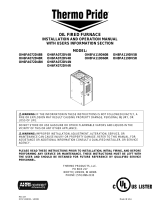
INSTALLATION OF RIELLO VENT KIT
This kit (AOPS8395) is to be used to connect a Riello BF3 or BF5 burner and Field vent term kit
to the furnace.
NOTICE: Installation must be performed by a qualified service technician.
NOTICE: AOPS8395 must be used in combination with AOPS8393.
NOTICE: Installer is required to supply the 4” inlet air pipe (dryer vent, metal vent, etc.)
Maximum15’.
STEP#1: Unpack contents and confirm all items have been packed.
STEP#2: Determine which side of furnace the combustion air supply will enter. Remove the
appropriate knockout.
STEP#3: Affix the 4”x3” reducer to the side casing using the pre-punched holes in the reducer
and side casing.
STEP#4: Connect the 4” side of the reducer to the 4” inlet air vent pipe (supplied by the
installer.) Once connected to the reducer, the other end can be connected to the field vent
termination kit (AOPS8393), if previously installed.
STEP#5: Attach the 3” flexible vent hose to the inlet of the burner and 3” side of the reducer.
Use hose clamps provided. Route the hose left or right, depending on which side of furnace
reducer is installed. Excess hose may be trimmed.
STEP#6: Install the Field Vent Kit (AOPS8393, not included.) If it has been previously been
installed, proceed to STEP#7.
STEP#7: Check combustions for proper set-up.
Recommended CO2:
MAXIMUM VENT 15’ MINIMUM VENT 5’
LOW FIRE 11 ½ % CO2 11 ½ % CO2
MID FIRE 11 ½ % CO2 11 ½ % CO2
HIGH FIRE 11 ½ % CO2 11 ½ % CO2
MO-442
ECN 4888-MA

MO-466
ECN 4888-MA
093009
1
INSTALLATION AND WIRING OF RIELLO POST-PURGE KIT
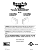
Before beginning this conversion, ensure that all of the parts are provided with this kit.
See parts list, Figure 1.
Model Part # Quantity Description
C5830010 1 AL1009 Post-purge Timer Board
C6504010 1 Technical instructions
C5313303 1 Wire nut
3001819 2 Sub-base terminal hardware (Clamp)
2261925 2 Sub-base terminal hardware (Threaded plate)
1011201 2 Sub-base terminal hardware (Screw)
40 BF3 & BF5
18022* 1 Mounting bracket (pre-drilled)
Figure 1
*This part provided by Thermo Products and is not part of P/N C7001088 Riello Post Purge Kit.
Note: If burner has AL1008 24v relay board installed, follow installation procedure steps 1 thru
18 & fig 2. If there is no AL1008 24v relay board, disregard steps 5, 6, 9 & 16.
Installation Procedure:
1. Shut off the electrical power to the appliance and oil burner using the main power
disconnect circuit breaker or fuse to the burner circuit.
2. Remove the burner cover.
3. Remove the burner control box from the sub-base.
4. Remove the wiring strain relief clamp and mounting screw. Retain the screw and clamp.
5. Remove AL1008 circuit board.
6. Remove mounting bracket.
7. Mount new mounting bracket, part# 18022, to the burner.
8. Mount the AL1009 circuit board to the right side of the mounting bracket.
9. Mount the AL1008 next to the AL1009 circuit board.
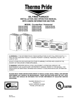
10. Install the threaded plate and clamp onto the sub-base at terminal #11 and terminal #12,
See Figure 2. Install the provided screws onto the plates and clamps but leave loose.

11. Rewire the sub-base as follows: refer to Figure 2 & Figure 3 to ensure the correct
wiring. Remove the white wire (motor) from terminal #7 and place it on terminal #12
with the yellow wire from the AL1009 circuit board and tighten the terminal screw.
12. Attach the gray wire from the AL1009 circuit board to the #7 terminal and re-tighten.
13. Remove the blue wire (oil valve coil) from the #2 terminal and place it on terminal #11
with one of the blue wires from the AL1009 circuit board and tighten the terminal screw.
Attach the remaining blue wire from the board to the #2 terminal and re-tighten.
14. Take either red wire and place it with the blue wire on terminal #6.
15. Take white wire from AL1008 and the white wire from AL1009, place them on the N
terminal. If burner is not equipped with AL1008, only wire the white wire from AL1009
to the N terminal. (Figure 3)
16. Take red wire from AL1008, place on the L terminal.
17. Take black wire from AL1008 and red wire from AL1009, to red power wire. If not
using AL1008, make connection from red wire on AL1009 to the L terminal & red power
wire. (Figure 3)
18. Take white wire from AL1008 and wire to white power wire. If not using AL1008,
connect white power wire to the N terminal. (Figure 3)
Figure 2
2

Figure 3
3
/