Page is loading ...

2009-06-25 1/4 400-610-010-A
The FLP12-GA programmable thermostat, specially designed for
floor heating installations, is equipped with two ultra-precise sen-
sors which allow temperature control by separately monitoring both
floor and ambient settings, thus providing greater comfort.
Installation Guidelines
To avoid electrical shock, turn off power to the heating system
at the main electrical panel. The installation must be performed
by qualified electrician.
Install the thermostat on an expanded (deep) electrical box.
Choose a location about 1.5 m (5 ft.) above the floor and on an
inside wall.
Avoid locations where there are air drafts (top of staircase, air
outlet), dead air spots (behind a door), direct sunlight or con-
cealed chimneys or stove pipes.
Supplied Parts
One (1) thermostat (control module and power base)
Two (2) screws
One (1) 4.6 m (15 ft.) floor sensor
One (1) flat-tip screwdriver
Four (4) solderless connectors for copper wires
NOTE: Special CO/ALR solderless connectors must be used
when connecting with aluminum conductors.
1) Separate the control module from the power base
Loosen the screw and separate
the control module from the
power base. The screw
remains captive on the power
base.
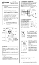
2) Connect the thermostat wires
Connect the thermostat to the floor heating system (load) and to the
power supply using solderless connectors for copper wires.
The floor heating braided shields or green wire as well as the power
supply copper ground wires must be secured to the ground terminal.
3) Connect the floor sensor
INSTALLATION
L2(N)
L1(L)
L2(N)
L1(L)
Floor heating system
Power supply
Red
Red
(White)
Red
Black
Black
Black
240 V (120 V)
Floor sensor
To remote control device (see section 4)
FLP12-GA
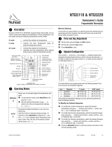
User Guide
Current program number when
Automatic mode is activated
Room or floor
temperature.
Arrow indicates
a setpoint
Indicates the amount
of power sent to the
floor heating system
Vacation
mode
Time and day
Economy setpoint
Manual
mode
Temperature
adjustment
ring
Day setting
To program
and view the
schedule
Comfort,
Economy
and Vacation
setpoints
Time setting
To clear a
program
To select a
mode or to exit
programming
mode
Comfort setpoint
Floor
minimum
and
maximum
temperature
(AF only)
GFCI test button
and light
To enable/disable heating
and to reset the GFCI
400-610-010-A (Flextherm FLP12 prog CAN) ENG.fm Page 1 Thursday, June 25, 2009 1:20 PM

2009-06-25 2/4 400-610-010-A
NOTE: Using an ohmmeter, verify the sensor’s integrity. It
must read between 8 to 12 K Ohms in order to obtain
temperature readings between 20°C and 30°C (68°F to
86°F).
• Insert the sensor wires through one of the two openings on the
power base and connect them to terminals 1 and 2 (no polar-
ity).
• The wire must be centered between the heating cables at a
distance of 30 to 60 cm (1 to 2 ft.) within the heating zone. Do
not cross the probe wire over the heating cables.
• The sensor should be placed in a neutral location, not near any
other heating or cooling sources.
• Secure the sensor to the floor using hot glue. It is necessary to
embed the sensor in the floor surface so it is at the same level
as the heating cables.
4) Connect the Econo Input (optional)
The thermostat is equipped with an Econo input which allows
connection of any remote control device equipped with a dry
contact. For more information, see the section on Vacation mode.
Insert the wires (use an 18 to 22 gauge flexible wire cable) through
one of the two openings on the power base.
Connect one end of the wires to terminals 2 and 3 of the power
base and the other end to the dry contact of a remote control device
(no polarity).
5) Set the DIP switches
The control module has four DIP switches to select the following
options:
Time and Temperature
Display (1)
•°F/12h
• °C/24h (default)
Early Start (2)
• E.S. On
• E.S. Off (default)
This function determines the
optimal system start time to obtain the desired temperature by the
set time. When this function is enabled, the system can be acti-
vated a few hours before the program’s start time.
Temperature Control (3)
This model offers the following three types of temperature control:
Permanent Backlight (4)
• P.B. On (The display remains lit all the time.)
• P.B. Off (Default. The display is lit for 12 seconds when the
adjustment ring or any button is pressed.)
6) Complete Installation
Install the power base onto the electrical box using the provided
screws and return the control module on the power base. Apply
power to the floor heating system.
NOTE: Keep the thermostat's air vents clean and free from
obstructions.
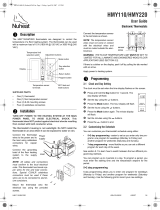
7) First Power On
When power is applied for the first time, the
screen displays 0:00 MO (Monday) as well as
the ambient/floor temperature.
If a problem occurs, one of the following mes-
sages will be displayed:
LO: the temperature is below 0°C (32°F) The heating indicator is
displayed and the system is activated.
HI: the temperature is above 70°C (158°F).
Er: the floor sensor is not connected properly or defective
(F temperature control) or the ambient sensor is defective
(AF temperature control).
To verify if the thermostat detects the floor sensor, select the
F temperature control (see DIP Switch Configuration). If the screen
displays Er, the floor sensor is not connected properly or defective.
If the screen displays the temperature, the sensor works.
9) Setting the Time and Day
nPress D, H or M to access the menu.
oPress H and M to set the time.
pPress D to select the day.
qPress MODE/RET to exit.
NOTE: If you remove the module from its base for more than
6 hours, the time and day must be reprogrammed.
This thermostat has a built-in Ground Fault Circuit Interrupter
(GFCI). In the event of a ground fault, the GFCI trips and quickly
stops the flow of electricity to prevent serious injury.
Definition of a ground fault
Instead of following its normal safe path, electricity passes through
a person’s body to reach the ground. For example, a defective floor
heating mat can cause a ground fault.
The GFCI does not protect against circuit overloads, short circuits,
or electrical shocks. For example, you can still receive an electrical
shock if you touch bare wires while standing on a non-conducting
surface such as a wood floor.
Ground Fault Protection Reset
When the GFCI trips, the TEST button illuminates (red) and GFI
appears on the screen. To reset the GFCI, switch the thermostat to
OFF and back to ON. The TEST button light will go off and GFI will
disappear.
If the TEST button illuminates and GFI appears on the screen
during normal operation, check if the fault has been caused by an
external interference such as a halogen light or an electric motor. In
this case, reset and test the GFCI. However, if the fault occurs
again for unknown reasons, cut power to the floor heating system
from the main electrical panel and have the installation verified by
an electrician.
GFCI Test
To ensure the GFCI is always in working order, test it once the ther-
mostat is installed and every month thereafter.
nIncrease the temperature sufficiently to start heating.
oWait for about 5 seconds until the heat intensity indicator ( )
appears on the screen.
pPress the TEST button at the top of the thermostat.
• If the TEST button does NOT illuminate, the test has failed.
Cut power to the heating system at the main electrical panel,
Temp. control Switch position Notes
Ambient
with floor limits DOWN (AF) Requires a floor sensor
Floor (default) UP (F) Requires a floor sensor
Ambient DOWN (AF) Use only when floor sensor is not installed.
Not recommended for floor heating
GROUND FAULT CIRCUIT INTERRUPTER
400-610-010-A (Flextherm FLP12 prog CAN) ENG.fm Page 2 Thursday, June 25, 2009 1:20 PM

2009-06-25 3/4 400-610-010-A
have an electrician verify the installation and, if necessary,
replace the thermostat.
•If the TEST button illuminates, continue to step 4.
qSwitch the thermostat to Off, then back to On.
• If the TEST button light goes off, the test has passed. Set
the thermostat back to the desired temperature and ignore
the remaining steps. The test is now completed.
• If the TEST button light remains on, the test has failed.
Continue to step 5.
rSwitch the circuit breaker (at the service panel) of the heating
system to off, then back to on.
sRepeat the test. If the test fails again, cut power to the heating
system at the main electrical panel, have an electrician verify
the installation and, if necessary, replace the thermostat.
.
The display is lit for 12 seconds when any button or adjustment ring
is pressed.
Comfort and Economy Setpoints
These setpoints are associated with the
schedule’s programs and are
preprogrammed as follows:
Comfort: temp. control AF: 21°C (70°F)
temp. control F: 28°C (82°F)
Economy: temp. control AF: 16.5°C (62°F)
temp. control F: 20°C(68°F)
To modify a setpoint value:
nSet the temperature using the adjustment ring.
oPress and hold the setpoint button ( or or ) until the icon
is displayed on the screen. The thermostat automatically
returns to normal display after 5 seconds.
Vacation Setpoint
This preprogrammed setpoint is used when the Vacation mode is
activated. To modify this value, repeat above steps.
Default: 10°C (50°F) for all control types.
Floor minimum and maximum limits (AF only)
The floor temperature limits prevent damage to the floor and ensure
personal safety. The thermostat generally turns heating On or Off to
control the ambient temperature. However if the floor temperature
goes outside the desired limits, the thermostat will unconditionally
turn heating On or Off to maintain the floor temperature within its
limits.
Default: min 5°C (40°F) and max 28°C (82°F)
nTurn OFF the thermostat.
oPress and hold CLR and turn ON the
thermostat. Release CLR only when the
minimum setpoint is displayed.
pSelect the minimum setpoint limit using the
adjustment ring.
qPress CLR to display the maximum value.
rSelect the maximum setpoint limit using the
adjustment ring.
sPress MODE/RET to exit.
NOTE: For the AF temperature control (ambient with floor
limits), the setpoint will always be maintained within the
minimum and maximum floor limits.
Automatic
Executes the schedule’s programs.
Press MODE/RET until the desired program
number is displayed (1 to 4).
To temporarily bypass the current program, set a
new temperature using the adjustment ring or
press one of the predefined setpoint buttons ( or ). The program
icon will flash to indicate the bypass. The new setpoint will be main-
tained until the beginning of the next program.
Manual
Maintains a constant temperature.
nPress MODE/RET until is displayed.
oSet the temperature using the adjustment
ring or press one of the predefined setpoint
buttons ( or or ).
Vacation
Maintains the Vacation setpoint during a
prolonged absence.
There are two ways to activate this mode:
nFrom the thermostat: press
oThe thermostat is equipped with an Econo input which allows
connection of any remote control system equipped with a dry
contact. When the contact closes, the thermostat automatically
switches from normal operating mode to the Vacation mode. In
this mode, the suitcase icon flashes and all buttons are locked.
When the contact opens, the thermostat returns to the normal
operating mode.
The schedule is executed when the Automatic mode is activated. It
controls your system by automatically switching from the Comfort
setpoint to the Economy setpoint at the preset times.
The preprogrammed schedule contains four (4) daily programs:
You can set up to four daily programs and each program can have
a different time for a total of 28 programs.
NOTE: It is sometimes easier to program the same schedule
for the entire week and then modify the exception days.
nPress PGM to access the programming mode.
BACKLIT DISPLAY
SETPOINTS
OPERATING MODE SELECTION
PREPROGRAMMED SCHEDULE
Programs MO TU WE TH FR SA SU
1Comfort6:006:006:006:006:006:006:00
2Economy 8:00 8:00 8:00 8:00 8:00 --:-- --:--
3Comfort 18:00 18:00 18:00 18:00 18:00 --:-- --:--
4Economy 22:00 22:00 22:00 22:00 22:00 22:00 22:00
SCHEDULE MODIFICATION
400-610-010-A (Flextherm FLP12 prog CAN) ENG.fm Page 3 Thursday, June 25, 2009 1:20 PM

2009-06-25 4/4 400-610-010-A
oPress D to select the day to be programmed or hold for
3 seconds to select all days.
pUse PGM to select the program number.
qUse H and M to set the program’s start time or use CLR to
erase the time (--:-- the program is inactive).
rRepeat steps 2 to 4 for the remaining programs.
sPress MODE/RET to exit.
NOTE: After 60 seconds of inactivity, the thermostat will
automatically exit programming mode.
GFCI: 5 mA
Accuracy: ± 0.5°C (0.9°F)
Memory backup: In the event of a power failure, an internal circuit
will save the programming. Only the time will have to be reset if the
power failure exceeds 6 hours. The thermostat will return to the
same operating mode in effect before the power failure.
FLEXTHERM LIMITED WARRANTY
Flextherm Canada Inc. (hereinafter “FLEXTHERM”) warrants to the purchaser that the
FLEXTHERM THERMOSTAT (hereinafter the “Product”) and once installed in conformity with
the instructions of FLEXTHERM, shall be free of defects, in either materials of workmanship
as described in this document.
COVERAGE PERIOD: This Limited Warranty becomes effective on the date of the original
purchase of the Product as supplied by FLEXTHERM and shall remain effective for a period
of one (1) year (twelve (12) consecutive months) from such date. This Limited Warranty is
valid for products purchased and installed in Canada only.
CONDITIONS: This Limited Warranty is only applicable to new and unused Products
purchased from FLEXTHERM, or its authorized re-sellers, provided the Installation
Requirements contained herein are met. Claims made for coverage under this Limited
Warranty must be addressed in writing, within seventy-two (72) hours from an event giving
rise to a claim, or the appearance of a defect, to: Flextherm Canada Inc. 1-800-353-9843. Any
parts replaced under the terms of this Limited Warranty become the property of FLEXTHERM.
Persons making claims for coverage must present FLEXTHERM with proof of purchase as
well as any documents FLEXTHERM may require.
WHAT FLEXTHERM WILL/WILL NOT DO: FLEXTHERM's obligations under this Limited
Warranty are limited to, at its sole discretion, repairing or replacing the thermostat originally
supplied in the Product that FLEXTHERM has determined to be defective in materials or
workmanship. FLEXTHERM shall replace the defective thermostat goods free of charge “ex
works” after the originals have been returned to us postage/freight prepaid. Replacement will
only be made for defective parts; and no allowance or reimbursement shall be made for
wages, labour and freight costs. With respect to the parts not manufactured by ourselves, we
shall only warrant for these to the same extent as our suppliers undertake a warranty
obligation towards ourselves.
Because of its ongoing commitment to product quality and innovation, FLEXTHERM reserves
the rights, at any time and without incurring any obligations, to revise, change, modify or
discontinue any specifications, features, designs or components.
INSTALLATION REQUIREMENTS: In addition to the requirements included in the current
FLEXTHERM Installation Guide, which is incorporated herein by this reference, the Product
must be installed in accordance with accepted standards.
WARNING: Failure to install the Product in conformity with your local electrical
Codes, as well as the Installation Guide, may cause fires. Failure to install the
Product according to the directives in the installation guide may damage the
cables/wiring and lead to Product failures, which are not covered under the
Limited Warranty.
EXCLUSIONS, ARE NOT WARRANTED: Failures resulting from improper installation;
Damage caused by abuse, improper installation, repairs, service, maintenance and/or
storage, modifications or use of parts not manufactured or supplied by FLEXTHERM;
Damage caused by abuse or neglect; regarding the Product; Damage caused by water,
submersion, accident, fire or any act of God; Incidental, consequential or other damages
(including labor costs, towing, inconvenience, loss of time or loss of income).
LIMITATIONS OF LIABILITY:
THIS WARRANTY IS EXPRESSLY GIVEN AND ACCEPTED IN LIEU OF ANY AND ALL
OTHER WARRANTIES, EXPRESSED OR IMPLIED, INCLUDING WITHOUT ANY
LIMITATION ANY WARRANTY OF MERCHANTABILITY OR FITNESS OR A PARTICULAR
PURPOSE. TO THE EXTENT THAT THEY CANNOT BE DISCLAIMED, THE IMPLIED
WARRANTIES ARE LIMITED IN DURATION TO THE LIFE OF THE EXPRESSED LIMITED
WARRANTY. INCIDENTAL AND CONSEQUENTIAL DAMAGES ARE EXCLUDED FROM
COVERAGE UNDER THIS LIMITED WARRANTY. SOME PROVINCES DO NOT ALLOW
FOR THE DISCLAIMERS, LIMITATIONS AND EXCLUSIONS IDENTIFIED ABOVE; AS A
RESULT, THEY MAY NOT APPLY TO YOU. THIS WARRANTY GIVES YOU SPECIFIC
RIGHTS WHICH MAY VARY FROM PROVINCE TO PROVINCE.
Neither FLEXTHERM re-sellers, installers or any other person is entitled or authorized to
make any affirmation, representation or warranty other than those contained in this Limited
Warranty. If the ownership of the Product is transferred during the Limited Warranty Coverage
period, the terms and conditions of the Limited Warranty shall apply to the new owner,
provided the new owner has proof, satisfactory to FLEXTHERM, of the date of first purchase
of the Product.
FLEXTHERM Canada Inc.
2400 de la Province Street
Longueuil, Quebec J4G 1G1 Canada
SPECIFICATIONS
Supply 120 VAC, 60 Hz 240 VAC, 60 Hz
Maximum load 15 A (1800 W) 15 A (3600 W)
AF F
Temperature display range:0°C to 70°C
(32°F to 158°F)
0°C to 70°C
(32°F to 158°F)
Temperature setting range:5°C to 30°C
(40°F to 86°F)
5°C to 40°C
(40°F to 104°F)
Comfort setpoint: 21°C (70°F) 28°C (82°F)
Economy setpoint: 16.5°C (62°F) 20°C (68°F)
Vacation setpoint: 10°C (50°F)
WARRANTY
1 800 FLEXTHERM (353-9843) / 450-442-9990
1 877 FLEXTHERM (353-9843) / 450-442-1099
www.flextherm.com
400-610-010-A (Flextherm FLP12 prog CAN) ENG.fm Page 4 Thursday, June 25, 2009 1:20 PM
/