Page is loading ...

Sensoray Model 417
ISAbus Thermocouple Interface
July 13, 2000

Chapter
Table of Contents
Chapter 1: Basics . . 1
Limited Warranty . . 1
Special Handling Instructions . . 1
Chapter 2: Introduction . . 2
Functional Description . . 2
Block Diagram . . 2
Specifications . . 3
Chapter 3: Hardware Configuration . . 5
Base Address . . 5
Option Shunt Table . . 5
Example . . 6
Application Worksheet . . 6
Chapter 4: Programming . . 7
Programming Model . . 7
Status Register . . 7
Control Register . . 8
Reset State . . 8
Sample Drivers . . 9
Visual Basic Drivers . . 9
C Language Drivers . . 11
80x86 Assembly Language Drivers . . 12
Commands . . 13
Definitions . . 13
Command Set . . 13
Set Sensor Type . . 14
Set Filter . . 15
Read Reference . . 16
Read Channel . . 17
Read Channel Group . . 18
Set Limits . . 19
Set Fail Mode . . 20
Read Alarms . . 21
50Hz Reject Mode . . 22
High Speed Mode . . 23
Read Version . . 24
Read Identifier . . 25
Calibrate . . 26
Sensor Table . . 27
Chapter 5: Sensor Connections . . 29
Connectors . . 29
Termination Boards . . 30
Thermocouples . . 30
DC Voltage . . 30
4-to-20 mA Current Loops . . 31
Solving Noise Problems . . 31
Chapter 6: Thermocouples . . 33
Overview . . 33
Reference Sensor . . 33
Ensuring Accuracy . . 33
Chapter 7: Theory of Operation . . 35
Software . . 35
Scanner . . 35
Post-processor . . 35
Command Processor . . 35
Hardware . . 36
Reference Standards . . 36
Signal Conditioning . . 36
Measurement Section . . 36
Timing . . 37
Scan Rate . . 37
Communication Latency . . 38
Processor Speed . . 38

Chapter
1
Basics
1
Limited Warranty
Sensoray Company, Incorporated (Sensoray) warrants the Model 417 hardware to be free from defects
in material and workmanship and perform to applicable published Sensoray specifications for two years
from the date of shipment to purchaser. Sensoray will, at its option, repair or replace equipment that
proves to be defective during the warranty period. This warranty includes parts and labor.
The warranty provided herein does not cover equipment subjected to abuse, misuse, accident, alteration,
neglect, or unauthorized repair or installation. Sensoray shall have the right of final determination as to
the existance and cause of defect.
As for items repaired or replaced under warranty, the warranty shall continue in effect for the remainder
of the original warranty period, or for ninety days following date of shipment by Sensoray of the
repaired or replaced part, whichever period is longer.
A Return Material Authorization (RMA) number must be obtained from the factory and clearly marked
on the outside of the package before any equipment will be accepted for warranty work. Sensoray will
pay the shipping costs of returning to the owner parts which are covered by warranty.
Sensoray believes that the information in this manual is accurate. The document has been carefully
reviewed for technical accuracy. In the event that technical or typographical errors exist, Sensoray
reserves the right to make changes to subsequent editions of this document without prior notice to
holders of this edition. The reader should consult Sensoray if errors are suspected. In no event shall
Sensoray be liable for any damages arising out of or related to this document or the information
contained in it.
EXCEPT AS SPECIFIED HEREIN, SENSORAY MAKES NO WARRANTIES, EXPRESS OR
IMPLIED, AND SPECIFICALLY DISCLAIMS ANY WARRANTY OF MERCHANTABILITY OR
FITNESS FOR A PARTICULAR PURPOSE. CUSTOMER’S RIGHT TO RECOVER DAMAGES
CAUSED BY FAULT OR NEGLIGENCE ON THE PART OF SENSORAY SHALL BE LIMITED TO
THE AMOUNT THERETOFORE PAID BY THE CUSTOMER. SENSORAY WILL NOT BE
LIABLE FOR DAMAGES RESULTING FROM LOSS OF DATA, PROFITS, USE OF PRODUCTS,
OR INCIDENTAL OR CONSEQUENTIAL DAMAGES, EVEN IF ADVISED OF THE
POSSIBILITY THEREOF.
Special Handling Instructions
The Model 417 circuit board contains CMOS circuitry that is sensitive to Electrostatic
Discharge (ESD). Special care should be taken in handling, transporting, and installing the 417
in order to prevent ESD damage to the board. In particular:
1. Do not remove the 417 from its protective antistatic bag until you are ready to
configure the board for installation.
2. Handle the 417 only at grounded, ESD protected stations.
3. Remove power from the ISAbus before installing or removing the 417 circuit board.

Chapter
2
Introduction
2
Functional Description
The Model 417 circuit board interfaces 32 process sensors directly to the ISAbus. Each of its 32
sensor channels may be independently configured, via software, to accept thermocouples, 4-to-20
mA current loops, or DC voltage. Sensor channels utilize true differential inputs to allow for wide
common mode variation.
Cold junction compensation and open-sensor detection is provided for thermocouples, and all
inputs are protected from high differential and common mode voltages.
Under firmware control, an onboard microprocessor continuously scans the 32 channels. As each
channel is scanned, the sensor signal is digitized, linearized, and converted to engineering units as
appropriate for the declared sensor type. Each channel’s most recently acquired data may be
quickly accessed by the ISAbus host.
Alarm limits are programmable for each channel. A status flag is set when limit violations occur,
enabling the host to quickly detect alarm conditions.
Communication with the ISAbus host takes place over two contiguous ports which may be
mapped anywhere in the system I/O address space. Local communication and scanning tasks
execute in a high-performance multitasking environment, optimizing both throughput and host
communication latency.
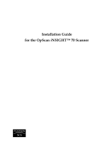
Block Diagram
DIGITIZER
µCOMPUTER
COMMAND
REGISTER
DATA
REGISTER
STATUS
REGISTER
SENSOR
SIGNALS
THERMOCOUPLE
REFERENCE
REFERENCE
STANDARDS
ISABUS INTERFACE
DIFFERENTIAL MUX
ISA BUS

3 Sensoray Model 417
Chapter 2 Introduction
Specifications
Table 1: General Specifications
Parameter
Condition
Specification
Min Typ Max Units
DC Input power +5V, ±5% 79 mA
+12V, ±5% 32
-12V, ±5% 22
Operating temperature -25 +85 °C
Common-mode rejection V
CM
< 5V
f < 1KHz
80 dB
Input Impedance 0.95 1.0 MΩ
Noise 3 sigma 5.7 7.5 µV
Channel measurement time 16.67 msec
Channel total time slot 22
Input overvoltage (with
or without applied pwr)
2 sec. max -70 +70 V
continuous -20 +20
A/D converter 17.5-bit integrating
Data format 16-bit integer, signed
ISAbus Interface Two contiguous 8-bit I/O ports
Full 16-bit address decode
Table 2: Sensor Specifications
Sensor Type Range Resolution Accuracy
Thermocouple
B
C
E
J
K
N
T
S
R
0°C to 1820°C
0°C to 1820°C
-270°C to 990°C
-210°C to 760°C
-270°C to 1360°C
-270°C to 1347°C
-270°C to 400°C
0°C to 1760°C
0°C to 1760°C
0.1°C
0.1°C
0.1°C
0.1°C
0.1°C
0.1°C
0.1°C
0.1°C
0.1°C
3.3°C
2.1°C
0.8°C
0.6°C
1.0°C
0.9°C
0.6°C
3.0°C
2.8°C
DC Voltage 0 to +5V
0 to +500mV
0 to +100mV
200µV
20µV
5µV
600µV
40µV
30µV
Current Loop 4-to-20 mA 0.01% 0.08%

Chapter
3
Hardware Configuration
3
Base Address
Before you install the coprocessor board in your system, its base I/O address must be set. The
base address may be set to any even value in the range 0000 to FFFE (hexadecimal) by means
of option shunts A1 through A15. These option shunts are factory set to locate the board at
address 02B2 and 02B3. To avoid conflicts, you must map the 417 into a two-port address
range that is unoccupied by other devices.
Option Shunt Table
If you require the 417 board to have a base address different from the default address , use the
following table to help to determine the proper shunt settings:
Table 3: I/O address jumpers: l = install shunt, m = remove shunt
Nibble
Value
High Address Byte Low Address Byte
Nibble3 (high) Nibble2 Nibble1 Nibble0 (low)
A15 A14 A13 A12 A11 A10 A9 A8 A7 A6 A5 A4 A3 A2 A1
0 l l l l l l l l l l l l l l l
1 l l l m l l l m l l l m
2 l l m l l l m l l l m l l l m
3 l l m m l l m m l l m m
4 l m l l l m l l l m l l l m l
5 l m l m l m l m l m l m
6 l m m l l m m l l m m l l m m
7 l m m m l m m m l m m m
8 m l l l m l l l m l l l m l l
9 m l l m m l l m m l l m
A m l m l m l m l m l m l m l m
B m l m m m l m m m l m m
C m m l l m m l l m m l l m m l
D m m l m m m l m m m l m
E m m m l m m m l m m m l m m m
F m m m m m m m m m m m m

Instruction Manual 6
Example
Set the base address to 0390:
Nibble3 = 0, so install A15-A12.
Nibble2 = 3, so install A11-A10 and remove A9-A8.
Nibble1 = 9, so install A6-A5 and remove A7 and A4.
Nibble0 = 0, so install A3-A1.
Application Worksheet
Use this worksheet to record and configure the Model 417 base address for your application.
1. Enter your target base address, in hexadecimal, in the space provided below:
2. Copy the hexadecimal address digits from the above box into the corresponding nibbles in the
spaces provided below. As in the example shown above, and using the Option Shunt Table as a
guide, darken in the circles representing option shunts that must be installed for each nibble.
3. Program the Model 417 circuit board option shunts as shown in the above table.
Nibble3 = 0 Nibble2 = 3 Nibble1 = 9 Nibble0 = 0
A15 A14 A13 A12 A11 A10 A9 A8 A7 A6 A5 A4 A3 A2 A1
l l l l l l m m m l l m l l l
Base Address:
Nibble3 = Nibble2 = Nibble1 = Nibble0 =
A15 A14 A13 A12 A11 A10 A9 A8 A7 A6 A5 A4 A3 A2 A1
m m m m m m m m m m m m m m m

Chapter
4
Programming
4
The Model 417 is programmed by means of commands. Commands are sent from the ISAbus mas-
ter—the “host” processor—to the 417. Some commands cause responses from the 417, which are
sent from 417 to host. This chapter explains the 417-to-host communication mechanism and
describes the command set.
Programming Model
The coprocessor occupies two consecutive port addresses in ISAbus I/O space. Each port has a
unique function for read and write operations.
The base port (417 board low port address) forms the data path between 417 and host. Commands
are sent to the 417 and responses are passed back to the host through this port, which consists of
two physical hardware registers: command and data. When the host sends a command to the 417,
it is really storing a byte in the command register. When the host reads a command response from
the 417, it is reading a byte from the data register. Because the command register is write-only and
the data register read-only, they are able to share the same I/O address.
The control port (base address + 1) consists of a read-only status register and write-only control
register. As the name implies, the status register supplies coprocessor status information to the
host. The control register is used to invoke soft resets.
Status Register
The status register provides the host with information needed for status monitoring and communi-
cation handshake control. When the host reads the status register, a byte of the following form is
returned:
Table 4: Programming model
Port Address Read Write
Base + 0: Data Data Register Command Register
Base + 1: Control Status Register Control Register
Table 5: Status Register
D7 D6 D5 D4 D3 D2 D1 D0
CRMT DAV ALARM FAULT X (DISREGARD THESE BITS)

Instruction Manual 8
Status register bits have the following functions:
Control Register
The control register provides a means for forcing a coprocessor soft reset. A soft reset is invoked
when any value is written to the control register port. The value of the data written to the control
port is ignored. A soft reset has the same effect on the coprocessor as a hard system reset.
Reset State
Following a soft or hard reset, the board state is initialized as follows:
• All channel sensor types switch to the 5-Volt, 500uV/bit range.
• All channel filter factors are reset to zero.
• All channels are programmed to fail high on open-sensor detection.
• All channel alarm limits are set to min/max values that disable the alarms.
• 60 Hertz Rejection Mode is active.
• Low-speed/High-resolution Mode is active.
Table 6: Status Register bit functions
Bit Function
CRMT
Command Register eMpTy, when set, indicates the 417 is ready to accept a
byte into its command register. Before writing a byte to the command
register, the host must test CRMT and verify that it is set to logic 1.
DAV
Data AVailable, when set, indicates that the 417 data register contains a new
data byte for the host. Before reading a byte from the data register, the host
must test DAV and verify that it is set to logic 1.
ALARM
When active (logic 1), indicates one or more programmed channel limits
were exceeded. Activated by any limit violation. Cleared by executing the
Read Alarms command.
FAULT
Indicates (1) a board reset is in progress, or (2) a board fault has been
detected. In normal operation FAULT is active (logic 1) for approximately
one-half second following a board reset. FAULT reflects the state of the
visible red LED fault indicator on the Model 417 circuit board.
IMPORTANT NOTE: The CRMT, DAV, and ALARM flags are not valid when
FAULT is active. After resetting the 417 board by means of either soft or hard
reset, the host should not attempt to handshake with the 417 until FAULT
changes to its inactive (logic 0) state.

9 Sensoray Model 417
Chapter 4 Programming
Sample Drivers
We recommend that you incorporate procedures in your application software that will conceal the
coprocessor handshake protocol from higher host software levels. This will serve to simplify your
programming requirements and reduce software maintenance costs.
This section contains simple software drivers that implement the required handshake protocol. In
addition, the Visual Basic routines listed below are referenced throughout this chapter in numerous
programming examples. Feel free to plagiarize and adapt these routines for your application.
Visual Basic Drivers
Note to Microsoft Visual Basic programmers: the Visual Basic programming language does not
support direct I/O access. You will need a third-party tool, or a simple DLL of your own design, to
access the Model 417 from within a Visual Basic application.
All Visual Basic code examples assume the availability of external procedures, “INP” and “OUT,”
for implementing direct I/O access.
‘*******************************************************************
‘ Status Port mask constants
‘*******************************************************************
Const CRMT = &H80 ‘Command Register eMpTy
Const DAV = &H40 ‘Data AVailable
Const ALARM = &H20 ‘Limit alarm(s) sounding
Const FAULT = &H10 ‘Board fault
‘*******************************************************************
‘ Storage declarations
‘*******************************************************************
Dim BaseAdrs As Integer ‘ Base address of 417 board
‘*******************************************************************
‘ Handshake a byte into the 417 command register
‘*******************************************************************
Sub SendByte (BasePort As Integer, CommandByte As Integer)
Do: Loop Until (INP(BasePort + 1) And CRMT) ‘wait for CRMT
Call OUT(BasePort, CommandByte) ‘send the byte
End Sub
‘*******************************************************************
‘ Handshake a byte from the 417 data register
‘*******************************************************************
Function ReadByte%(BasePort As Integer)
Do: Loop Until (INP(BasePort + 1) And DAV) ‘wait for DAV
ReadByte = INP(BasePort) ‘read the byte
End Function

Instruction Manual 10
‘*******************************************************************
‘ Read a signed, 16-bit integer value from the 417, MSB first.
‘*******************************************************************
Function ReadWord%(BasePort As Integer)
Dim Lval As Long
‘ Handshake the high byte (MSB) from Model 417
Lval = ReadByte(BasePort)
‘ Handshake LSB from Model 417 & concatenate with high byte
Lval = Lval * 256 + ReadByte(BasePort)
‘ Adjust sign, if necessary
If Lval > 32767 Then Lval = Lval - 65536
‘ Set return value
ReadWord = Lval
End Function
‘*******************************************************************
‘ Send a signed, 16-bit integer value to the 417, MSB first.
‘*******************************************************************
Sub SendWord(BasePort As Integer, Value As Integer)
‘ Handshake the high byte (MSB) to Model 417
Call SendByte(BasePort, Value \ 256)
‘ Handshake the low byte (LSB) to Model 417
Call SendByte(BasePort, Value)
End Sub

11 Sensoray Model 417
Chapter 4 Programming
C Language Drivers
//======================================================
// Write a command byte to the 417 command register.
//======================================================
void adSendByte ( short base_port, short cmd_byte )
{
while ( ( inp( base_port + 1 ) & 128 ) == 0 ) ; // wait for CRMT
outp ( base_port, cmd_byte ) ; // send the byte
}
//======================================================
// Read a data byte from the 417 data register
//======================================================
short adReadByte ( short base_port )
{
while ( ( inp ( base_port + 1 ) & 64 ) == 0 ) ; // wait for DAV
return ( inp ( base_port ) ) ; // read the byte
}
//======================================================
// Write 16-bit value to the 417
//======================================================
void adSendByte ( short base_port, short cmd_word )
{
adSendByte ( base_port, cmd_word >> 8 ) ; // send high byte
adSendByte ( base_port, cmd_word ) ; // send low byte
}
//======================================================
// Read 16-bit value from the 417
//======================================================
short adReadWord ( short base_port )
{
short hiByte = adReadByte ( base_port ) << 8 ; // read hi byte
return ( hiByte | adReadByte ( base_port ) ) ; // rd/concat lo byte
}

Instruction Manual 12
80x86 Assembly Language Drivers
;***********************************************************
; Handshake a command byte into the 417 command register.
; Entry:DX points to 417 base port address.
; AL contains command byte to send to 417.
;***********************************************************
;INITIALIZE DRIVER
XMIT: PUSH AX ; Save command byte to be sent to 417
INC DX ; Set address pointer to status port
;WAIT FOR “COMMAND REGISTER EMPTY”
XLOOP: IN AL,DX ; Read status port
TEST AL,80H ; and test CRMT status flag
JE XLOOP ; Loop until command register is empty
;SEND COMMAND BYTE TO 417 BOARD
DEC DX ; Set address pointer to command register
POP AX ; Restore command byte
OUT DX,AL ; and write it into command register
RET ;EXIT DRIVER
;***********************************************************
; Handshake a byte from the 417 data register.
; Entry:DX points to 417 base port address.
; Exit:AL contains data byte read from 417.
;***********************************************************
;INITIALIZE DRIVER
RCV: INC DX ; Set address pointer to status port
;WAIT FOR “DATA AVAILABLE”
RLOOP: IN AL,DX ; Read 417 status port
TEST AL,40H ; and test DAV status flag
JE RLOOP ; Loop until data register is full
;READ DATA BYTE FROM 417 BOARD
DEC DX ; Set address pointer to 417 data register
IN AL,DX ; Read byte from data register
RET ;EXIT DRIVER

13 Sensoray Model 417
Chapter 4 Programming
Commands
The 417 is accessed through a simple yet powerful built-in command set. Commands vary in
length depending on the size of encapsulated data. In some cases invocation of a command will
cause the coprocessor to return data to the host. In such cases the host must read the command
response before issuing another command.
Each command consists of at least one byte. The first byte of each command adheres to the above
format. The opcode—always present in the first command byte—specifies the function to be per-
formed. A channel number, present in the Channel field, is required by commands that address a
particular channel. In other commands, the Channel field is sometimes used as an extension of the
Opcode field.
Definitions
The following definitions and conventions are used throughout this chapter when describing com-
mands and responses:
• The symbolic name “Chan” represents a coprocessor channel number. Valid channel
numbers range from 0 through 31, inclusive.
• A byte is represented as a number or expression contained by parenthesis. For example,
(16 + Chan) represents a byte having a value equal to 16 plus a channel number.
• A byte string is represented as an ordered sequence of bytes, separated by commas. The
sequence is defined from left to right. For example, the byte string
(95 + Chan),(5),(0) contains three bytes and begins with the leftmost byte.
• A command consists of a byte string which is passed from host to 417.
• A command response consists of a byte string which is passed from 417 to host.
Command Set
The remainder of this chapter discusses the coprocessor command set. Each command function is
described along with the associated command and response byte strings.
Sample code snippets are provided to illustrate command usage. All programming examples are
written in Visual Basic. If you are employing a different developer’s environment for your applica-
tion, these programming examples can be easily converted to the language of your choice.
Table 7: Format of first command byte
D7 D6 D5 D4 D3 D2 D1 D0
OPCODE CHANNEL

Instruction Manual 14
Set Sensor Type
This command declares the type of sensor connected to a channel. Typically, this command is exe-
cuted once for each channel during the coprocessor initialization sequence (i.e., after a hard or soft
reset). Each execution of this command specifies the sensor type for a single channel, therefore 32
invocations must occur to declare sensor types for all 32 channels.
A two-byte sequence forms the command string. The first byte contains the Set Sensor Type com-
mand opcode and target channel number. The second byte contains a Sensor Definition Code
(SDC). Each sensor type is assigned a unique 8-bit SDC. Refer to the Sensor Table at the end of
this chapter for a complete list of sensor definition codes.
Notes:
1. Undeclared channel sensor types default to the 5-Volt input range, SDC 0.
2. Declaring an invalid sensor type may result in unpredictable behavior.
3. Declaring a sensor type as “Disabled” inhibits scanning of the corresponding channel,
resulting in increased throughput for all remaining active channels.
4. Sensor data is not available immediately after declaring a channel’s sensor type; you must
wait for one complete scan loop before valid sensor data can be accessed.
COMMAND: (32 + Chan), (SensorDefinitionCode)
RESPONSE: NONE
VB Code Example:
‘**********************************************************
‘ Generic procedure used to declare any sensor type.
‘**********************************************************
Sub SetSensorType(BasePort%, Channel%, TypeCode%)
Const SET_TYPE = 32 ‘ SET SENSOR TYPE command opcode
‘ Send the command string to the coprocessor board
Call SendByte(BasePort, SET_TYPE + Channel)
Call SendByte(BasePort, TypeCode)
End Sub
‘**********************************************************
‘ Configure channel 2 for interface to K thermocouple.
‘**********************************************************
Const TYPE_K = 3 ‘ K thermocouple SDC (from Sensor Tables)
Call SetSensorType(BaseAdrs, 2, TYPE_K)

15 Sensoray Model 417
Chapter 4 Programming
Set Filter
This command establishes a software single-pole low-pass filter for the specified channel. The
second command byte specifies unsigned filter factor, F, which may have any value from 0 to 255,
inclusive. The relationship between F and filter percentage, P, is:
All channel filter factors default to zero after a reset. This effectively disables the filters and maxi-
mizes channel response. A non-zero factor in electrically noisy environments may help to reduce
measurement noise.
Rather than computing the theoretical value of filter constants, we recommend that you experi-
ment with different values to find the best response/noise tradeoff. Some applications, however,
require knowledge of the filter time constant. This expression describes the relationship between
time constant t, expressed in seconds, and filter factor F:
COMMAND: (160 + Chan), (FilterFactor)
RESPONSE: NONE
VB Code Example:
‘*********************************************************************
‘ Generic procedure to set filter factor on any channel.
‘*********************************************************************
Sub SetFilter(BasePort%, Channel%, FiltFactor%)
Const SET_FILT = 160 ‘ SET FILTER CONSTANT command opcode
‘ Send command string to coprocessor board
Call SendByte(BasePort, SET_FILT + Channel)
Call SendByte(BasePort, FiltFactor)
End Sub
‘*********************************************************************
‘ Set up channel 4 with a 12.5% low-pass filter. To convert filter
‘ percentage (0 to 100%) to filter factor, multiply by 2.55.
‘*********************************************************************
Call SetFilter(BaseAdrs, 4, 12.5 * 2.55)
FInt2.55
P×()
=
t
NumActiveChannels–
45ln
F
256
---------
×
-----------------------------------------------------
≅

Instruction Manual 16
Read Reference
This command returns the reference temperature from optional Sensoray termination boards
(TBs), such as Models 7409TB, 7409TC and 7409TDIN. This function is useful for monitoring
thermocouple reference junctions and can also serve as a debugging aid during 417 installation and
application development.
Since two TBs can be connected to the 417, you must specify which TB you are addressing; the
command byte includes a TB address code for this purpose. Set the TB address code to 0 to access
the TB connected to channels 0-15, or to 1 to access the TB connected to channels 16-31.
The returned, signed 16-bit integer, temperature value is scaled to 0.10ºC per bit. If the addressed
TB is not connected to the 417 board, this command will return a meaningless value.
COMMAND: (96 + TBcode)
RESPONSE: (BoardTemp MSB), (BoardTemp LSB)
VB Code Example:
‘****************************************************************
‘ Generic procedure to read temperature (in degrees C) from a TB.
‘****************************************************************
Function GetTbTemperature!(BasePort%, TbCode%)
Const READ_TB = 96 ‘ READ BOARD TEMPERATURE command opcode
‘ Send command opcode to 417 board
Call SendByte(BasePort, READ_TB + TbCode)
‘ Read TB temperature data and convert to degrees C
GetTbTemperature = ReadWord(BasePort%) * 0.1
End Function
‘****************************************************************
‘ Read temperatures from both TBs and convert to degrees F
‘****************************************************************
Dim TbCode As Integer ‘ TB address code
Dim DegreesF(0 to 1) As Single ‘ Array to hold temperature data
For TbCode = 0 To 1
DegreesF(TbCode) = 1.8 * GetTbTemperature(BaseAdrs, TbCode) + 32.0
Next TbCode

17 Sensoray Model 417
Chapter 4 Programming
Read Channel
This command returns the most recently acquired sensor data from one channel. The returned
value is scaled as a function of the channel’s sensor type and is always represented as a signed,
16-bit integer. Refer to the Sensor Table at the end of this chapter for a list of sensor scaling fac-
tors.
COMMAND: (Chan)
RESPONSE: (Data MSB), (Data LSB)
VB Code Example:
‘****************************************************************
‘ Return the most recent Engineering Units data from any channel.
‘****************************************************************
Sub ReadChannel!(BasePort%, Channel%, Scalar!)
‘ Send command to 417 (Opcode = 0)
Call SendByte(BasePort, Channel)
‘ Read chan data from 417 and convert to Engineering Units
ReadChannel = ReadWord(BasePort) * Scalar
End Sub
‘**************************************************************
‘ Assume channel 6 has been configured for 5-Volt input signal,
‘ 200uV per bit. Read the voltage measured at channel 6.
‘**************************************************************
Dim ChanSixVolts As Single
Dim Scalar As Single
Scalar = 0.0002 ‘ From Sensor Tables, scalar = 200uV/bit
ChanSixVolts = ReadChannel(BaseAdrs, 6, Scalar)
‘**************************************************************
‘ Assume channel 4 has been configured for a K thermocouple,
‘ 0.1C/bit. Read the temperature measured at channel 4.
‘**************************************************************
Dim DegreesC As Single
DegreesC = ReadChannel(BaseAdrs, 4, 0.1)

Instruction Manual 18
Read Channel Group
This command returns the most recent sensor data from a group of eight channels. Sensor data is
scaled as a function of the declared sensor type for each channel, just as it is scaled when using the
Read Channel command. Refer to the Sensor Table at the end of this chapter for a list of sensor
data scalars.
A Group Code is included in the command to specify which eight-channel group is to be returned.
Group Code 0 returns channels 0-7, 1 returns channels 8-15, 2 returns channels 16-23, and 3
returns channels 24-31. The response string consists of channel data ordered by increasing channel
number, beginning with the lowest channel number in the group. For example, Group Code 2 will
return data in the following channel order: 16, 17, 18, ... , 23.
COMMAND: (104 + GroupCode)
RESPONSE: (GroupChan 0 MSB), (GroupChan 0 LSB),
(GroupChan 1 MSB), (GroupChan 1 LSB),
(GroupChan 2 MSB), (GroupChan 2 LSB),
(GroupChan 3 MSB), (GroupChan 3 LSB),
(GroupChan 4 MSB), (GroupChan 4 LSB),
(GroupChan 5 MSB), (GroupChan 5 LSB),
(GroupChan 6 MSB), (GroupChan 6 LSB),
(GroupChan 7 MSB), (GroupChan 7 LSB)
VB Code Example:
‘*******************************************************************
‘ Read integer data from 8-channel group into DataArray().
‘*******************************************************************
Sub ReadChannelGroup(BasePort%, GroupCode%, DataArray%())
Dim Channel As Integer ‘ ChanNum and DataArray() index
Const READ_GROUP = 104 ‘ READ CHANNEL GROUP command opcode
‘ Send command to 417 and read channel data into DataArray()
Call SendByte(BasePort, READ_GROUP + GroupCode)
For Channel = (8 * GroupCode) TO (8 * GroupCode + 7)
DataArray(Channel) = ReadWord(BasePort)
Next Channel
End Sub
‘******************************************************************
‘ Fetch integer data from all 32 channels.
‘******************************************************************
Dim Group As Integer ‘ Channel Group specifier
Dim IntDataArray(0 To 31) As Integer ‘ Array to hold chan data
For Group = 0 to 3
Call ReadChannelGroup(BaseAdrs, Group, IntDataArray())
Next Group

19 Sensoray Model 417
Chapter 4 Programming
Set Limits
This command declares signed, 16-bit integer, upper and lower alarm threshold limits for a chan-
nel. An alarm will “sound” if the scaled sensor data strays below the lower limit or above the upper
limit. The alarm “sounds” by setting the ALARM bit in the status register.
All limits assume default values when the coprocessor is reset. Low limits reset to -32768, and
high limits to 32767. These default values effectively disable the alarm function. To disable the
lower limit, specify a lower limit of -32768. Similarly, declare an upper limit of 32767 to disable
the upper limit.
When a channel limit is exceeded, both channel limits are reset to their default values. This pre-
vents the alarm from sounding again after the host has acknowledged the violation. The host must
reprogram the violated limit to re-arm it.
COMMAND: (64 + Chan),
(HiLimit MSB), (HiLimit LSB),
(LoLimit MSB), (LoLimit LSB)
RESPONSE: NONE
VB Code Example:
‘**********************************************************************
‘ Generic procedure to set alarm limits for one channel.
‘**********************************************************************
Sub SetLimits(Channel%, LoLimit%, HiLimit%)
Const SET_LIMITS = 64 ‘SET LIMITS command opcode
‘ Set channel alarm limit values on 417 board
Call SendByte(BasePort, SET_LIMITS + Channel)
Call SendWord(BasePort, HiLimit)
Call SendWord(BasePort, LoLimit)
End Sub
‘**********************************************************************
‘ Channel 7 is configured for a K thermocouple, 0.1C/bit. Program limits
‘ so that alarm will “sound” if temperature strays outside 400C-to-450C.
‘**********************************************************************
Dim Scalar As Single ‘Data scalar appropriate for sensor type
Dim HiLim As Integer ‘High alarm limit threshold
Dim LoLim As Integer ‘Low alarm limit threshold
Scalar = 0.1 ‘K thermocouple data scalar (from table)
HiLim = 450.0 / Scalar ‘compute high alarm limit value
LoLim = 400.0 / Scalar ‘compute low alarm limit value
Call SetLimits(BasePort, LoLim, HiLim)‘Set channel 7 alarm limits
/