ResQcra Operaon & Maintenance Manual
© Safequip 2015

2
www.safequip.co.uk
Operaon & Maintenance Manual
Table of Contents
Assembly & Inaon .................................................................................................... 9
Unpacking ................................................................................................................9
Inaon Systems ...................................................................................................... 9
Manual Inaon (Procedure) ................................................................................. 10
Manual Inaon (Top Up) ...................................................................................... 10
Drainage Trunks .....................................................................................................11
Deate & Re-Packing Procedure ................................................................................ 12
General Instrucons ...............................................................................................12
General ................................................................................................................... 13
Yearly Maintenance ............................................................................................... 13
Cleaning .................................................................................................................13
Repair of Inatables ............................................................................................... 14
Transom ......................................................................................................................15
Illustrated View ...................................................................................................... 15
Transom Parts List ..................................................................................................15
Fings ......................................................................................................................... 16
Fings Illustrated View ..........................................................................................16
Fings Parts List ....................................................................................................16
Safety ..........................................................................................................................17
Warranty .....................................................................................................................17
Notes ........................................................................................................................... 18
Operaon ...................................................................................................................... 3
ResQcra Arrangement ........................................................................................... 3
Introducon .............................................................................................................4
Features & Accessories ............................................................................................ 5
Buoyancy Tubes .......................................................................................................6
Deck & Keel .............................................................................................................. 7
Fit-out ............................................................................................................................ 8
Lifelines .................................................................................................................... 8
Hand holds ...............................................................................................................8
Towing Eyes/Load securing points ........................................................................... 8
Capsize Re-Right Lines .............................................................................................. 8
Transom ...................................................................................................................8
Wear Patches & Fendering ....................................................................................... 8
Transportaon Stowage Valise ................................................................................. 8
Loose Accessories ......................................................................................................... 9
Oponal Extras .............................................................................................................9

3
www.safequip.co.uk
Operaon & Maintenance Manual
Operaon
ResQcra Arrangement

4
www.safequip.co.uk
Operaon & Maintenance Manual
Introducon
All inaon chambers are interconnected with one way valves and are protected
with individual pressure release valves. They can be topped up from the stern of
the cra without the need to move.
The SIT range of cra can be equipped for air drop/helicopter deployment, 4
point li, towing, and self-recovery.
The SIT range of Inatable Boats have been developed to meet the demanding
requirements of military and Rescue Services, where deployment me,
performance and stowed dimensions are crical.
Cra from the SIT 380 to 530 range are in service throughout the United Kingdom
and several European countries. Their performance and handling are proven to
compete with any other cra in its class.

5
www.safequip.co.uk
Operaon & Maintenance Manual
Features & Accessories
* All table data is an approximaon, every cra will vary slightly.
Specicaons
ResQcraft
380
400
470
500
530
ResQcraft
380
400
470
500
530
No of People
6
8
10
12
14
Components
Max Payload incl. Engine (Kg)
700
950
1300
1400
1725
Engine Capacity (Hp)
30
30
55
55
75
Chambers - Tubes
3
5
5
5
5
Engine Weight (Kg)
80
85
110
110
125
Removable Deck/keel
1
1
1
1
1
Shaft Length (20")
Long
Long
Long
Long
Long
Transom
50mm Composite, no
wood
Drainage
2 self Bailer trunks +
one way hull drain
DIMENSIONS
External Lifeline
1
1
1
1
1
External Length (m)
3.8
4
4.7
5
5.3
Internal Lifeline
1
1
1
1
1
External Beam (m)
1.7
2.2
2.2
2.2
2.2
Deck Line
1
1
1
1
1
Internal Length (m)
2.85
3
3.55
3.85
4.15
Carry Handles
7
7
7
7
7
Internal Beam (m)
0.84
1.2
1.2
1.2
1.2
Vertical Lift Points optional extra
4
4
4
4
4
Buoyancy Tube
Pannier Bags
1
1
1
1
1
Diameter (m)
0.42
0.5
0.5
.5
0.5
Paddles and Stowage
2
2
2
2
2
Deck Area (m²)
1.65
2.3
3.1
3.5
3.9
Capsize Re-Right Lines
2
2
2
2
2
Tube Volume (Litres)
1400
1715
1850
1975
2015
Load Securing Points
4
4
4
4
4
Deck + Keel Volume (Litres)
350
400
540
620
685
Cylinder Sleeve Optional extra
1
1
1
1
1
Stowed Weight (kg)
65
85
90
105
120
Pump and Repair Kit
1
1
1
1
1
Stowed Dimensions (m)
Stowage Valise
1
1
1
1
1
Length
1.2
1.5
1.5
1.5
1.5
Tow Points Rear
2
2
2
2
2
Width
0.6
0.7
0.7
.7
0.7
Tow Points Forward
2
2
2
2
2
Height
0.4
0.4
0.5
.5
0.6

6
www.safequip.co.uk
Operaon & Maintenance Manual
Buoyancy Tubes
To ll the fourth and h chambers, the opposite side rear Inate/Deate valve
must be used.
The buoyancy tubes are ed with a pressure relief valve (PRV) on the port
side of the “V” shaped bow chamber which prevents excess tube pressure. All
chambers will vent to this PRV.
Each of the inaon chambers are ed with a clearly labelled Inate/Deate
valve. These allow individual chambers to be inated and topped up during
service and for all chambers to be deated quickly.
The main buoyancy tube of the ResQcra is made up of 5 inatable chambers,
with the excepon of the 3.8 which has 3 chambers.
The buoyancy tubes are manufactured, using 1670 dtx polyester Hypalon®
neoprene. The side chambers and the “V” shaped bow chamber are all linked by
a series of Inter-Connecng Valves (ICV). These pressure sensive valves allow all
chambers to be lled from the two rear inaon valves at the end cones.
During the lling process, as the rst (rear) chamber reaches operaonal
pressure, its ICV opens and allows the next chamber to ll. The third chamber to
ll will be the “V” shaped bow chamber.

7
www.safequip.co.uk
Operaon & Maintenance Manual
Deck & Keel
The deck incorporates a cut-out at the transom to allow any free standing water
to be drained away. It also incorporates an inaon/deaon valve located near
the transom as well as a pressure relief valve.
Externally the keel line is protected from abrasion with a high density EPDM
rubber wear protecon strip, bonded to the underside of the hull skin.
Keel Strake
The main hull construcon is made up of 1670 dtx polyester Hypalon® neoprene.
The inatable deck with integrated keel is capable of maintaining a rigid cra
under maximum load. The 150DTTM deck has a double fabric/Hypalon skin for
extremely high wear resistance and durability. The excellent Shock Migaon
characteriscs inherent in the inatable 150DTTM deck and its superior rigidity
negate the need for a cumbersome rigid deck plate or extra tubes under the
deck, as used on other cras.

8
www.safequip.co.uk
Operaon & Maintenance Manual
Fit-out
Capsize Re-Right Lines
The cra is ed with a total of 2 pull out lifelines located externally on the port
side of the buoyancy tubes. These are intended to aid in re-righng a capsized
cra. They are not to be used to capsize the cra as the layout of the securing of
the ip lines may pull away the ng from the tubes. In the unlikely event of a
capsize, these lines will be located by a reecve arrow on the side tube.
Transom
The transom is a composite construcon Fibre-reinforced Plasc (FRP). It includes
self-bailers with 2 scuppers and a lower drain bung. The transom includes an
engine mounng plate and rubber pad. The transom is congured to accept a
Long sha 20”, single or twin outboard motor installaon. The transom can be
made to accept a Short sha 17” Outboard.
Wear Patches & Fendering
The buoyancy tubes are ed with an-slip patches running along the top surface
all around the cra. They also incorporate single rubber fendering all around the
sides of the tubes for added protecon.
Transportaon Stowage Valise
For transportaon of the cra, it is stowed in a heavy duty fabric valise secured
with 4 large plasc buckles. The bag includes 6 moulded handles for easy
carrying.
Lifelines
The buoyancy tubes are ed with external and internal lifelines running along
both sides of the cra. An addional line runs centrally on the deck as well.
Lifelines are 12mm nylon rope supported by bonded combined lifeline and D-Ring
patches.
Hand holds
There are moulded hand holds located on each side of the buoyancy tubes and
one located centrally on the bow.
Towing Eyes/Load securing points
The cra are ed with a number of stainless steel D-rings and are suitable for
towing or load securing. Eyes suitable for towing are heavily reinforced. Three of
these are mounted beneath the bow, a further two are mounted on top of the
sponsons near the transom and two mounted on rear of transom. Further eyes,
suitable for load securing are located around the perimeter of the deck; these are
mounted directly above the internal lifeline aachment points.

9
www.safequip.co.uk
Operaon & Maintenance Manual
Loose Accessories Assembly & Inaon
Supplied with the cra are the following accessories:
• Fabric Valise
• Repair Kit
• Inaon Pump with Hose
• Paddle Kit
• User Manual
Oponal Extras
The cra has a range of oponal extra’s which can be specied. A 16 gallon fuel
tank can be added and posioned at the bow, as well as an addional rectangular
6 gallon tank which is portable and easily removable. Securing straps are ed
for either fuel tank.
Unpacking
Unpacking the cra from its stowage valise in readiness for inaon must be
carried out on a large at surface free from debris or sharp edges which may
pose a risk of damage or puncture. The chosen area should oer enough room
for the cra to fully inate and for its operator to access all necessary valves.
To unpack the cra, release the four buckles and unwrap the valise from the
rolled cra. The valise can be laid out at beneath the cra to oer a clean
surface on which to inate.
Inaon Systems
There are two methods of manual inaon, using a Din ng Compressed Air
cylinder with Compact Inaon hose or a Handpump with hose which is supplied
with the cra.
The deck and keel are inated using the valves located by the transom, one
inate/deate valve. Once this has reached maximum pressure (9 PSI), the
pressure relief valve (PRV) will hiss indicang you are at opmum pressure. The
PRV valves are located by the bow of the cra and also on the deck.
The system works by air passing into the rst chamber. When the chamber lls
up and reaches maximum pressure, the interconnecng valve (ICV) to the next
chamber releases to allow air into that chamber. The push ng within the valve
can be opened to release air by turning an-clockwise, however ensure the valve
is turned fully clockwise in order to inate.

10
www.safequip.co.uk
Operaon & Maintenance Manual
Manual Inaon (Procedure)
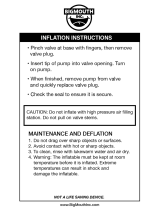
To start the manual inaon, A pump can be ed in the port stern C7 Inaon valve rst. Screw o the protecve cap, push in central spigot of C7 inaon valve and
turn clockwise. Insert the pump hose or Compressed air inaon kit hose into the valve and proceed to inate. Once Port side has been fully inated to the bow of the
tubes when the PRV blows o. Move onto the Starboard stern inaon valve and repeat the procedure. Inate the deck using the same procedure.
Ensure that when removing the Inaon hose, you do not rotate the push ng an-clockwise as this will open up the valve and allow air to escape.
To open, push in central cross spigot,
twist clockwise. (Fig.2)
Remove Cap (Fig.1)
Replace cap (Fig.3) A6 Pressure Relief valves: (Fig.4)
Require no interacon. They will
self-seal when the pressure is low
enough.
Ensure the valves are not blocked or
covered.
Manual Inaon (Top Up)
If there is a loss of pressure in any of the chambers, the corresponding inaon valve can be used to top up to factory pressure.
Fig. 1 Fig. 2 Fig. 3 Fig. 4

11
www.safequip.co.uk
Operaon & Maintenance Manual
Drainage Trunks
Fig. 5 Fig. 6 Fig. 7
Drainage trunks should be in the
closed posion unless drainage is
required. To close pull the line down
through the cleat unl the trunk is
fully raised. (Fig.5)
To open pull up on the free line
coming out of the clam cleat and
allow line to pass back through the
cleat, (Fig.6)
unl the trunk is lowered. (Fig.7)

12
www.safequip.co.uk
Operaon & Maintenance Manual
Deate & Re-Packing Procedure
3. Fold.
Fold port and starboard tubes in towards the centre and hold in place.
The tubes in this posion should be the same width as the transom.
Fold the transom forward.
Fold the port and starboard cones on to the transom.
4. Rolling.
Roll up the cra, transom toward bow.
Keep the roll as ght as possible.
Encourage trapped air to escape.
5. Packing.
Lay out the stowage valise.
Posion rolled up cra in centre of valise.
Wrap cra in valise - Narrow ends rst.
Fasten and ghten clips.
Fig. 8
2. Deaon.
Open all the inate/deate valves
on the cra. Turn centre spigot of
inaon valve an-clockwise. Allow
air to escape. (Fig.8)
If available, use extracon pump to
remove the air within the cra.
Leave deate valves open
throughout packing procedure and
when in the stowage valise.
General Instrucons
The following instrucons are provided to enable the correct packing of the cra
post operaonal use. The packing procedure is the same whether the reason for
packing is for a short term during or returning from an operaon, or for long term
storage.
Long Term Storage: Before the cra is stored for an extended period it should be
fully washed down with fresh clean water, disinfect the cra to remove bacteria,
and then leave to completely dry out. It is also recommended to before packing
away to apply chalk dust to inside of the boat, this will help preserve the cra
and reduce wear & tear.
Short Term Storage: The cra should be as clean and dry as possible before being
stowed post operaonal use. If the cra is stored in a wet or unclean condion it
should be unpacked, cleaned and dried as soon as possible.
1. Posion cra on a at surface free from debris.

13
www.safequip.co.uk
Operaon & Maintenance Manual
General
Before Use:
Ensure there are no hazards in your work area (broken glass, metal screws, thorns
etc.). The product is not fragile, but taking care will ensure a long service life.
Inate product and ensure it is at the correct working pressures:
Whenever possible use a hand pump or compressed air cylinder ed with a
calibrated regulator
Check any valves for grit and foreign bodies – clean if necessary.
Check product all over for wear and tear – repair if necessary (see below).
Always Carry:
A method of repair, such as patches and glue or “Clam Shell™” or similar.
A method of re-Inaon – Pump or Compressed Air cylinder
Aer Use:
Inspect for wear and tear - repair if necessary (see below).
Repair/replace damaged items.
Re-eect any emergency repairs – Get professional help for major repairs.
Clean product by washing with water and a mild detergent. Storing the product
wet and dirty will not immediately damage the product but may shorten its life.
If pung into storage dry thoroughly and pack, apply chalk dust if going into
storage for a long period (6 months+).
Store product in a cool dry place that is not prone to the extremes of
temperature and humidity. Airow circulaon is preferable as the product will
likely sll be moist aer cleaning and drying.
Yearly Maintenance
• Inaon test – inate product to recommended pressure and leave inated
for 24 hours. When checked the pressure should be within approximately
10%. Allow for temperature and atmospheric pressure change.
• Wear and tear inspecon, patch if necessary.
• Glue down any loose edges and patches.
• Clean with water and a mild detergent.
Cleaning
If the Product becomes soiled, cleaning is most eecve using a good quality
proprietary inatable boat cleaning compound aer rst washing with water and
a mild detergent.
Do not aempt to use harsh solvents without expert advice.

14
www.safequip.co.uk
Operaon & Maintenance Manual
Repair of Inatables
If the inatable becomes torn or punctured: -
Find the puncture, large tears and holes will be easy to nd, smaller pin holes
may be less obvious and can be found using soapy water and a paint brush or
sponge. The leaking pinhole will produce soap bubbles quite readily.
If puncture/tear is within 1” of a seam, contact Safequip or SIT for technical
advice.
Make sure that the surrounding area is clean and dry, preferably 24 hours before
starng the repair work.
Prepare a patch from the repair material provided, at least 50mm larger in all
direcons than the area of damage.
Thoroughly rub down the surrounding area and the back of the patch with the
medium abrasive paper provided.
Apply a thin layer of adhesive to both surfaces and allow to dry completely (20 –
30 minutes).
Apply a second coat and when almost dry place the prepared surfaces in contact
and press together rmly, rubbing down with a smooth hard object such as the
back of a spoon or a narrow roller. Rub from the centre, outwards, making sure
to remove all air bubbles.
Leave for at least 24 hours before use.
Clean o any excess adhesive around the patch, as this will tend to go brown with
exposure to sunlight.

15
www.safequip.co.uk
Operaon & Maintenance Manual
Transom
Illustrated View
Transom Parts
TRANSOM
1 Transom 1 1 1
2 Engine Mounng Plate 1 1 1
3 Engine transom Pad 1 1 1
4 Large Flow Scuppers 2 2 2
5 Self Bailer Rope Cleat 2 2 2
6 Li Point 2 2 2
7 Keel Drain 1 1 1
8 Bung and Socket 1 1 1

16
www.safequip.co.uk
Operaon & Maintenance Manual
Fings
Fings Illustrated View
Fings List
FITTINGS
1 Carry Handle 11 13 13
2 Re-Right Lines 2 2 2
3 External Lifeline 2 2 2
4 Internal Lifeline 2 2 2
5 2” D ring on 5” Patch 7 7 7
6 Life line Tunnel on 5” Patch 14 16 16
7 Combined D ring and Lifeline Tunnel 8 10 10
8 Combined D ring and Lifeline D ring 4 4 4
9 Reinforced D-Ring Patch 5 5 5

17
www.safequip.co.uk
Operaon & Maintenance Manual
Safety
Warning
The use of solvents can be highly ammable, Irritang to skin and prolonged
exposure or inhalaon may cause serious harm.
Suitable respiratory face mask and gloves should be used at all mes when
handling these substances.
Safety
Beware of oshore winds and currents.
Exceeding the stated crew, capacity and engine size will have an adverse eect on
the boats performance.
Ensure when loading the cra the weight and persons are evenly distributed.
Spills of engine oil or petrol should be cleaned up quickly and not le to stand on
the fabric of the cra as this may cause damage.
Ensure cra is fully inated before use. A parally or soly inated cra will not
perform well.
Ignoring these warnings and the maintenance instrucons in this manual could
seriously damage the cra or the user/crew.
Warranty
Low Pressure Inatable Warranty
Inatable Hypalon® products supplied by Safequip Ltd are manufactured under
BS EN ISO 9001: 2008 quality standards and come with a 2 year manufacturer’s
warranty.
The warranty covers all aspects of the manufacturing processes and general
workmanship.
The ORCA Hypalon® 828 & 866 material used in the manufacturing process has a
separate 5 year warranty from the date of supply. And the ORCA Drop Thread 270
material 2 year warranty.
It is recommended that all inatable products are inspected on a regular
basis and serviced annually by an approved service centre, otherwise this will
invalidate the terms of the warranty.
Any warranty claims must be submied quong the serial number, type of usage,
the age of the product and details of any problems.
If possible it would also be helpful to quote the original order number the
product was purchased on, or alternavely quote our invoice number.
Please contact us in the rst instance to discuss any issues

18
www.safequip.co.uk
Operaon & Maintenance Manual
Notes
SERIAL NUMBER ........................................................................................................
DATE OF PURCHASE ...................................................................................................
SERVICE RECORD
Address Details
...................................................................................................................................
...................................................................................................................................
...................................................................................................................................
...................................................................................................................................
DATE OF SERVICE COMMENTS / DEFECTS PERSON CARRYING OUT SERVICE SIGNATURE NEXT SERVICE DUE

19
www.safequip.co.uk
Operaon & Maintenance Manual
Notes

20
www.safequip.co.uk
Operaon & Maintenance Manual
SALES
Safequip Ltd
Unit 4 Block 3 Dumyat Business Park
T u l l i b o d y
Clackmannanshire
FK10 2PB
Tel: +44 (0) 1259 727835
Fax: +44 (0) 1259 727825
Email: [email protected]o.uk
Website: www.safequip.co.uk
REPAIRS & SERVICING
Safequip Ltd (Service Center)
Unit 1 Dukes Court Industrial Estate
Prudhoe
Northumberland
NE42 6DA
Tel: +44 (0) 1661 830232
Email: repairs@safequip.co.uk
©Safequip 2015
/