Page is loading ...

The Toro Promise - Limited One Year Warranty
For Technical Support
P.O. Box 489
Riverside CA 92502
1-800-231-5117
© 2003 The Toro Company
All rights reserved
Lawn Genie
®
Automatic Anti-Siphon Valve
Installation and Operation Guide
For Models L7034, L7010
Please read instructions completely before
attempting to install or operate the valve.
1095501 Rev. C
The Toro Company and its affiliate, Toro Warranty Company, pursuant to an agreement
between them, jointly warrants, to the owner, against defects in material and workmanship
for a period of one year from the date of purchase.
Neither The Toro Company nor Toro Warranty Company is liable for failure of products not
manufactured by it even though such products may be sold or used in conjunction with
Toro products.
During such warranty period, we will repair or replace, at our option, any part found to be
defective.
Return the defective parts to the place of purchase.
Our liability is limited solely to the replacement or repair of defective parts. There are no
other express warranties.
This warranty does not apply where equipment is used, or installation is performed, in any
manner contrary to Toro’s specifications and instructions, nor where equipment is altered
or modified.
NEITHER THE TORO COMPANY NOR TORO WARRANTY COMPANY IS LIABLE FOR
INDIRECT, INCIDENTAL OR CONSEQUENTIAL DAMAGES IN CONNECTION WITH
THE USE OF EQUIPMENT, INCLUDING BUT NOT LIMITED TO: VEGETATION LOSS,
THE COST OF SUBSTITUTE EQUIPMENT OR SERVICES REQUIRED DURING
PERIODS OF MALFUNCTION OR RESULTING NON-USE, PROPERTY DAMAGE OR
PERSONAL INJURY RESULTING FROM INSTALLER’S NEGLIGENCE.
Some states do not allow the exclusion or limitation of incidental or consequential
damages, so the above limitation or exclusion may not apply to you.
ALL IMPLIED WARRANTIES, INCLUDING THOSE OF MERCHANTABILITY AND
FITNESS FOR USE, ARE LIMITED TO THE DURATION OF THIS EXPRESS
WARRANTY.
Some states do not allow limitations of how long an implied warranty lasts, so the above
limitation may not apply to you.
This warranty gives you specific legal rights and you may have other rights which vary from
state to state.
L7010 8/7/03 1:34 PM Page 1
RELEASED Version ©Toro 2005-2005

The L7034 (3/4") and L7010 (1") are anti-siphon valves with a flow adjustment screw,
and can be operated electronically or manually.
In areas where freezing conditions occur, make provisions for draining the system.
Use a shut-off valve installed on the main line feeding the sprinkler system. To assure
complete drainage of the valve after water supply is shut off, electrically energize each
valve for at least a few minutes (dry run). This vents any automatic valve, allowing
maximum drainage.
Where local water pressure exceeds 80 psi, a pressure regulator should be used.
[See Uniform Plumbing Code, Sec. 1007 (b)]. It is advisable to use a regulator with
any automatic valve to assure long life as well as uniform and controllable operation.
The anti-siphon valve should be installed 6"-12" above the highest head so at
no time will the anti-siphon valve be subject to back pressure or drainage. There must
not be any valve downstream of the anti-siphon valve. [See Uniform Plumbing Code,
Sec. 1003 (2) (7)]. Check local codes before installation.
Anti-Siphon valves must not be operated continuously for more than twelve (12)
hours. (See American Society of Sanitary Engineering Standard 1001, Sec, 1.5.2.4.).
Step 1. Flush the line thoroughly before installing the valve. Use teflon tape on
male threads.
Step 2. Screw the valve onto the supply pipe threads hand tight. Use a wrench only
to straighten the valve into position.
Step 3. Screw the outlet pipe into the valve with a wrench, hold the valve by hand as
the outlet pipe is tightened.
Step 4. Wiring to the valves can be placed underground under the pipes. Use approved
underground type wire and be sure all splices are joined with wire nuts and
sealed with vinyl cement or other suitable water-proofing cement. Run one
common wire to each location to serve all the valves at that location. Use 18
gauge direct burial wire for runs not over 800 feet and 14 gauge wire over 800
feet. The wire is available from your dealer in 2, 3, 4, 5, 6, 7 and 8 color coded
wires. Connect the solenoid to a timer that uses an approved class 2, 24V
transformer as a power source.
Step 5. Turn the white flow control screw knob clockwise until it seats, closing the
valve. Turn the water supply on. The valve will remain closed.
Step 6. Turn the black manual bleed screw knob counterclockwise.This will allow water
to flow through the valve as the flow control is backed out. Adjust the flow con-
trol for desired flow. Tighten the manual bleed screw and the valve will close.
Electrical requirements are 18 V ac minimum at the solenoid.
Inrush volt-amps @24 V ac 11.50 VA
Inrush current @24 V ac 0.48 Amps
Holding volt-amps @24 V ac 5.75 VA
Holding current @24 V ac 0.24 Amps
NOTE: Due to varying regulations, check your local codes.
Lawn Genie
®
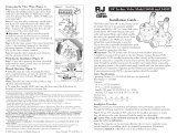
14
PRESSURE LOSS – PSI
FLOW RATE – GPM
12
10
8
6
4
2
0
0 5 10 15 25 30
L7034
14
PRESSURE LOSS – PSI
FLOW RATE – GPM
12
10
8
6
4
2
0
0 5 10 15 25 30 35 40
L7010
Recommended
Not Recommended
L7010 8/7/03 1:34 PM Page 2
RELEASED Version ©Toro 2005-2005
/