Page is loading ...

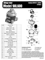
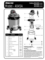
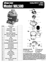
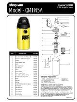
ITEM DESCRIPTION PART NO.
Standard Accessories:
10' (3.05m) x 1
1
/
2
" (3.81cm) Hose
(2) 1
1
/
2
" (3.81cm) Metal extension wands
14" (35.56cm) Metal master nozzle
14" (35.56cm) Squeegee shoe
14" (35.56cm) Brush shoe
14" (35.56cm) Rug shoe
1
1
/
2
" (3.81cm) Crevice tool
1
1
/
2
" (3.81cm) Round brush
6" (15.24cm) Utility nozzle
Model 950A
1
1
/
4
" x 1", type BT Truss 15083-99-1
head slotted screw
2 Handle 21303-01-1
3 Motor housing cover 21314-01-8
4 Foam insert 21321-00-5
5 Foam insert 21320-00-7
6 Power cord 04290-96-1
7 Strain relief bushing 34002-99-8
8 Foam insert 21324-00-9
9 #10 x
3
/
4
" Screw hex head 15039-99-3
type AB
10 Switch 82303-04-1
11 Electrical panel 21352-01-8
12 #10 x 3" slotted hex head 15058-99-3
type BT screw
13 Upper housing 21396-01-5
14 Lower housing 21397-02-1
15 Exhaust cage 21309-00-0
16 Exhaust sleeve foam 21318-00-1
17 Foam insert 21325-00-6
18 Upper motor gasket 20700-00-1
19 Ground Screw 17008-99-6
20 Motor 13496-97-1
21 Wire nut 05001-99-5
22 Lower motor gasket 20716-00-7
23 Grid plate 88607-00-7
24 Ball float 00811-00-0
25 Latch 85501-62-3
26 Lid cage assembly 89855-31-6
27 Filter frame clips 99384-00-0
28 Screw #10 x
1
/
2
" hex head 15061-99-7
29 Foam sleeve 90585-62-1
30 Full filter frame 30037-00-6
31 16 Gal. tank assembly 84991-97-5
(includes 3 brackets & 6 screws)
32 Inlet fitting 64510-71-2
33 Inlet lock ring 64511-71-0
34 Drain plug cap 10620-20-1
35 Tank bracket assy. 42099-96-0
36 Full polyester filter 90638-00-8
37 High efficiency collection filter bag 91907-10-5
38 Screw #10 x 1" hex head 15096-99-3
1
2
3
6
4
8
17
5
7
12
13
10
11
9
9
14
15
16
18
20
21
22
23
24
25
27
30
26
36
29
9
28
31
32
33
35
37
38
34
19
Catalog 950-20-10
(16 Gal.)
Limited One-Year Wrranty
Shop-Vac Corporation warrants all Industrial, Commercial, and
Contractor vacuum cleaners for one year from date of purchase to
correct by repair or parts replacement without charge any product
defect due to fautly material or workmanship, provided that the vac-
uum cleaner is not used for rental service.
SC87516-10

3
16
1
5
6
4
22
2
3
15
15
14
7
10
11
12
20
21
9
8
15
13
5
5
19
18
15
17
Dolly Assembly Instructions
Tools required:
(2)
1
/
2
inch open end wrenches, (2)
7
/
16
inch open end wrenches,
or a socket set and a hammer.
1. Insert 2
1
/
2
inch long bolt through center hole in rear frame,
attach split lockwasher, nut and tighten securely.
2. Attach handle brace to back of rear frame with
5
/
8
inch long
machine screws, lockwashers, and nuts. (Finger tighten
only.)
3. Position main frame inside rear frame. Attach (2)
5
/
8
inch long
machine screws, lockwashers and nuts in both sides.
Tighten securely.
4. Attach handle uprights, inside main frame (make sure but-
tons at top face inward) using
5
/
8
inch long machine screws,
lockwashers and nuts. (Finger tighten only.) Align holes at
top of handle braces with holes in handle uprights. Attach
with 1
1
/
4
inch long machine screws, lockwashers and nuts.
(Tighten securely.)
5. Go back and tighten machine screws at bottom of uprights
and braces.
6. Attach caster sockets (open end down) to front of main frame
using
5
/
8
inch long machine screws, lockwashers and nuts.
Insert casters into sockets.
7. Attach handle onto uprights by pushing down and holding
buttons in on uprights.
8. Place tank retaining bracket through slot and bolt in rear
frame and screw on knob.
9. Slide bumper down over main dolly frame until it bottoms out.
10.Place axle upright on a hard surface and hammer on (1) cap
nut. Place (1) wheel on axle and slide down to cap nut. Slide
axle through rear of frame and slide on other wheel. Before
assembling cap nut on other end of axle, be certain dolly is
assembled correctly. (You may place tank on dolly and tight-
en knob of retaining bracket to be sure of correct assembly.)
11. After ensuring dolly is assembled correctly remove tank and
place dolly on side with installed cap nut on hard surface and
hammer second cap nut on axle.
ITEM DESCRIPTION PART NO.
1 Handle (14”)-10 Gal. 20855-02-9
(16”)-20 Gal. 20855-03-7
2 Handle upright 20856-01-9
3 Handle brace 20857-01-7
4
1
/
4
- 20 x 1
1
/
4
" Hex head machine 09074-99-8
screw (Black)
5
1
/
4
" External tooth lockwasher 23010-99-4
6
1
/
4
- 20 Hex nut (Black) 13035-99-3
7 Rear dolly frame (14”)-10 Gal. 20832-00-2
(16”)-20 Gal. 20837-00-1
8 Main dolly frame (14”)-10 Gal. 20831-00-4
(16”)-20 Gal. 20836-00-3
9
5
/
16
-18 x 2
1
/
2
" Hex head bolt 09073-99-0
10
5
/
16
" - Split lockwasher 02005-99-9
11
5
/
16
- 18 Hex nut 13003-99-1
12 Tank retainer bracket 20853-00-8
13 Threaded knob 23301-00-5
14 Axle (14”)-10 Gal. 24406-00-1
(16”)-20 Gal. 24407-00-9
15
1
/
4
- 20 x
5
/
8
" Hex head
machine screw 09028-99-4
16
1
/
4
- 20 Hex nut 13001-99-5
17 Caster socket 75400-01-0
18 Caster 67729-00-4
19 Bumper (14”)-10 Gal. 87810-01-6
(16”)-20 Gal. 87811-01-4
20 10” Wheel (25.4cm) Black 24205-00-7
Grey 24207-00-3
21 Cap nut 43002-99-7
22 *Metal accessory basket (14”)-10 Gal. 99358-01-2
(16”)-20 Gal. 99358-02-0
*Optional
/


