
AA11 Instructions Rev02
Normal latching and non-latching setting.
Wide dynamic range of sensitivity with High/Low sensitivity settings.
Pulse count options, one or two pulses.
Power on reset.
Six or seven wire connection.
Six wires: 2 power, 2 anti-tamper, 2 alarm condition.
Optional Res : Set/Unset - used for latching.
Fast and easy installation.
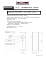
Dimensions: 21 x 26 x 87 mm.
Indication via LED
IMPACTOR
AA11 -
A SMART SHOCK SENSOR
Features of IMPACTOR
TM
A smart Shock Sensor

AA11 Instructions Rev02
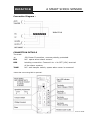
Connection Diagram :
CONNECTION DETAILS
Terminals
+-
12V Power Connection, reverse polarity protected.
RLY
N.C. opens when alarm occurs.
RES
Latching connection. Connect it to + Ve SET (12V) terminal
of the alarm system.
TAMP
N.C. anti-tamper switch, opens when cover is removed.
*Note that connecting RES is optional.
IMPACTOR
A SMART SHOCK SENSOR
IMPACTOR

AA11 Instructions Rev02
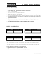
CALIBRATION MODE
1. Install IMPACTOR
TM
according to Installation instructions.
2. Power on IMPACTOR
TM
3. Choose sensitivity level before calibrating.
4. Make sure switches 2 and 3 are ON.
5. Tap the coverage area and watch the LED. If detection occurred the LED will light
6. To reduce sensitivity so that detection will appear only on a stronger impact, turn
Adjustment clockwise.
7. To increase sensitivity so that detection will appear on a lighter impact, turn
Adjustment anti-clockwise.
8.
Set switches according to the mode of operation that you choose.
MODES OF OPERATION
-Use low sensitivity in a noisy environment - near roads, airports, factories, etc.
-Use high sensitivity in a quiet environment when you need a large coverage area.
Do not calibrate unit and then change sensitivity.
To change sensitivity you must recalibrate the unit.
All LED alarm indications will clear upon setting the alarm.
Switch 1 Sensitivity Switch
OFF Low Sensitivity
ON High Sensitivity
Switch 2 Pulse Count
OFF Dual Pulse Count
ON Single Pulse Count
Switch 3 Latching Switch
OFF Latch Mode
ON Normal Mode
Switch 4 Spare Switch
OFF Spare
ON Spare
IMPACTOR
A SMART SHOCK SENSOR

AA11 Instructions Rev02
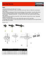
INSTALLATION INSTRUCTIONS
1. Select the intended position for installation, ensuring the surface is clean and clear of any
irregularities.
2. Remove the cover of the sensor by removing the screw cap, unscrewing the single fixing
screw then lift off the front cover.
3. Carefully lift the printed circuit board from the base.
4. Move the base plate to the mounting position and mark the desired fixing holes.
5. If rear cable entry is required, cables should be threaded through the rear of the base.
6. Fix the base in position using screws, (some hard surfaces may require pilot drilling).
Ensure the base is in complete contact with the mounting surface.
7. Carefully push the printed circuit board onto the base.
8. Terminate the connections to sensor.
9. If side cable entry is being used, remove the appropriate knockout from the cover.
10. Go to the calibration section and apply power to the sensor.
11.
After the unit is calibrated to your satisfaction, replace the cover of the sensor,
tighten the
fixit screw and check its response to the desired impact.
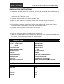
Technical data
Supply Voltage
9V - 16V DC
Current – normal mode
- alarm
15mA @ 12V dc
18mA @ 12V dc
Temperature limit
-10°C to +55°C
Relative humidity at 30°C
0 - 90%
Dimensions (mm)
21 x 26 x 87 mm
Indicator
Red LED
Sensitivity settings
High /Low sensitivity options
Latching modes
Non latch/latch modes
Pulse count
Selectable one or two pulses
Relay contact resistance
150mA 24V Resistive: 10 1/10 Watt
Relay open time At least one second
Coverage
Surface
Radius
Brick Wall 2.5m
Steel 3.0m
Wood 3.5m
Concrete 1.5m
Plywood 4.0m
Glass 3.5m
IMPACTOR
A SMART SHOCK SENSOR

AA11 Instructions Rev02
Due to our policy of continuous improvement we reserve the right to change specification without
prior notice.
Errors and omissions accepted. These instructions have been carefully checked prior to
publication. However, no responsibility can be accepted by Challenger Security Products for any
misinterpretation of these instructions.
CHALLENGER SECURITY PRODUCTS
10 Sandersons Way
Marton
Blackpool
FY4 4NB
Tel No: 0044 1253 791 888
Tech No: 0044 1253 792 898
Website: www.challenger.co.uk
Email: enquiries.challenger@adivision.co.uk
-
 1
1
-
 2
2
-
 3
3
-
 4
4
-
 5
5


Ask a question and I''ll find the answer in the document
Finding information in a document is now easier with AI
Related papers
Other documents
-
HUANUO HNFLS5 Installation guide
-
 Eurex 044060 Datasheet
-
Bosch CPK51-18 User manual
-
Allied Telesis Freezer 6870 User manual
-
 SPEX SamplePrep 6875-230 Freezer/Mill Operating instructions
-
 fortessa FTEB1 Engineer Manual
-
Optex FX-360 Technical Manual
-
Risco ShockTec Plus Grade 3 Installation guide
-
 fortessa FTEB3 Engineer Manual
-
Eurotherm Action Instruments Product Handbook HA136731 Owner's manual


