BEA LZR-I30 is a laser scanner for industrial doors with a detection range of up to 30 ft x 30 ft. It can detect objects in both the opening and safety fields, and can be configured to activate outputs based on the detection of objects in either field. The LZR-I30 also features a virtual push-button learn function, which allows you to create activation zones within the optional field. This makes it ideal for use in applications where you need to be able to open the door manually, such as in a warehouse or loading dock.
BEA LZR-I30 is a laser scanner for industrial doors with a detection range of up to 30 ft x 30 ft. It can detect objects in both the opening and safety fields, and can be configured to activate outputs based on the detection of objects in either field. The LZR-I30 also features a virtual push-button learn function, which allows you to create activation zones within the optional field. This makes it ideal for use in applications where you need to be able to open the door manually, such as in a warehouse or loading dock.


-
 1
1
-
 2
2
-
 3
3
-
 4
4
-
 5
5
-
 6
6
-
 7
7
-
 8
8
-
 9
9
-
 10
10
-
 11
11
-
 12
12


BEA LZR-I30 is a laser scanner for industrial doors with a detection range of up to 30 ft x 30 ft. It can detect objects in both the opening and safety fields, and can be configured to activate outputs based on the detection of objects in either field. The LZR-I30 also features a virtual push-button learn function, which allows you to create activation zones within the optional field. This makes it ideal for use in applications where you need to be able to open the door manually, such as in a warehouse or loading dock.
Ask a question and I''ll find the answer in the document
Finding information in a document is now easier with AI
Related papers
Other documents
-
Shimano CS-6400 Service Instructions
-
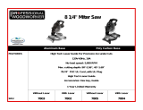 Professional Woodworker 7802 User manual
-
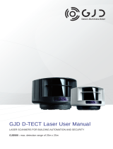 GJD GJD500 User manual
-
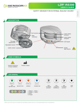 Sensorio LZR-RS300 User manual
-
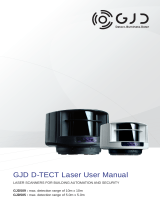 GJD GJD505 User manual
-
 GJD GJD509 User manual
-
FAAC X-Guard sensor for barriers Owner's manual
-
Marantec LZR-H100 Owner's manual
-
BEA Americas LZR-MICROSCAN T User guide
-
Reliable Iron i30 User manual


