White Rodgers 1311-102 Hydronic Zone Controls Troubleshooting guide
- Type
- Troubleshooting guide

RESIDENTIAL
ZONE VALVES
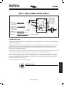
TO AUXILIARY CIRCUIT
FOR OPERATING BURNER
AND/OR CIRCULATOR.
(NOTE: IF SAME TRANS-
FORMER POWERS BOTH
THE AUXILIARY CIRCUIT
AND THE WATER VALVE,
CONNECT AUXILIARY CIR-
CUIT TO TERMINALS 1 AND
3 INSTEAD OF 2 AND 3.)
TRANSFORMER
INTERNAL
WIRING
EXTERNAL
WIRING
MOTOR
HOLDING
CONTACT
CONTACT
SIDE "A"
OPEN
POSITION
SIDE "B"
OPEN
POSITION
R
LINE
CLOSED
POSITION
THERMOSTAT
SIDE "A" OF
MOTOR SWITCH
SIDE "B" OF
MOTOR SWITCH
5
W
4
1
3
2
6
6
SCHEMATIC OF VALVE
TROUBLESHOOTING:
1)Attachavoltmetertoterminals1and2.Power(24volts)shouldalwaysbepresenton1and2.Ifpowerisinterruptedcheck
transformer or power source.
2)Withavoltmeterattachedasabove,jumperterminals5and4toverifythevalveopens.Ifpowerispresenton1and2but
thevalvefailstoopencheckconnections.Replacemotorassembly(replacementMotor#F19-0097)ifconditionpersists.
Whenthevalveopens,breaktheconnectionbetween5and4andjumperbetween5and6.Thevalveshouldclose.Ifthe
valve fails to close replace motor assembly.
3) Terminals 2 and 3 (auxiliary circuit) become the same point electrically when the valve opens. Because terminal 2 is 24 volts
hot, a voltmeter should read 24 volts between terminal 3 and terminal 1 (neutral) when the valve is open.
Note: If the auxiliary circuit terminals (2 and 3) are being attached to a control circuit with a separate transformer the trans-
formers must be in phase or one transformer may be damaged. If phasing the transformers is not possible a 24 volt isolation
relay can be installed with the coil attached to terminals 1 and 3 and the contacts can be used to operate the control circuit.
The relay will energize when the valve opens.
For complete installation instructions visit our website.
TERMINALS 1, 2 = POWER TO VALVE
1= 24 VAC NEUTRAL
2 = 24 VAC HOT
TERMINALS 5,4,6 = SPDT THERMOSTAT
5 = POWER (SAME AS 2 INTERNALLY)
4 = OPENS VALVE
6 = CLOSES VALVE
TERMINALS 2, 3 = AUXILIARY SWITCH
2, 3 BECOME SAME POINT ON CALL FOR HEAT
TERMINALS 1, 3 = POWER OUT TO AUXILIARY CIRCUIT ON CALL FOR HEAT
1311 Three Wire Zone Valve
WIRING
?
See next
page
TECHNICAL HELP
1361 Troubleshooting................ see next page
TECHNICAL HELP
www.white-rodgers.com
225
-
 1
1

White Rodgers 1311-102 Hydronic Zone Controls Troubleshooting guide
- Type
- Troubleshooting guide
Ask a question and I''ll find the answer in the document
Finding information in a document is now easier with AI
Related papers
Other documents
-
Carrier 58PAV User manual
-
Intertherm M1 User manual
-
Bunn-O-Matic FMD-5 User manual
-
-
Bunn FMD-1 User manual
-
Bryant FFMANP030000 User guide
-
-
Trane FF Installation, Operation and Maintenance Manual
-
Trane VAV-UCM 4.2 Installation & Maintenance Manual
-