
Frymaster, a member of the Commercial Food Equipment Service Association, recommends
using CFESA Certified Technicians.
24-Hour Service Hotline 1-800-551-8633
AUG 2005
H14/H17/H22 SERIES
ELECTRIC FRYERS
Service & Parts Manual
Beginning with Series Code AN
*8195794*

NOTICE
IF, DURING THE WARRANTY PERIOD, THE CUSTOMER USES A PART FOR THIS
ENODIS EQUIPMENT OTHER THAN AN UNMODIFIED NEW OR RECYCLED PART
PURCHASED DIRECTLY FROM FRYMASTER/DEAN, OR ANY OF ITS AUTHORIZED
SERVICE CENTERS, AND/OR THE PART BEING USED IS MODIFIED FROM ITS
ORIGINAL CONFIGURATION, THIS WARRANTY WILL BE VOID. FURTHER,
FRYMASTER/DEAN AND ITS AFFILIATES WILL NOT BE LIABLE FOR ANY
CLAIMS, DAMAGES OR EXPENSES INCURRED BY THE CUSTOMER WHICH
ARISE DIRECTLY OR INDIRECTLY, IN WHOLE OR IN PART, DUE TO THE
INSTALLATION OF ANY MODIFIED PART AND/OR PART RECEIVED FROM AN
UNAUTHORIZED SERVICE CENTER.
DANGER
Copper wire suitable for at least 167°F (75°C) MUST be used for power
connections.
DANGER
The electrical power supply for this appliance MUST be the same as
indicated on the rating and serial number plate located on the inside of the
fryer door.
DANGER
This appliance MUST be connected to the voltage and phase as specified
on the rating and serial number plate located on the inside of the fryer
door.
DANGER
All wiring connections for this appliance MUST be made in accordance
with the wiring diagrams furnished with the equipment. Wiring diagrams
are located on the inside of the fryer door.
DANGER
Do not store or use gasoline or other flammable vapors and liquids in the
vicinity of this or any other appliance.
WARNING
Do not attach accessories to this fryer unless fryer is secured from tipping.
Personal injury may result.
WARNING
Frymaster fryers equipped with legs are for permanent installations. Fryers
fitted with legs must be lifted during movement to avoid damage and
possible bodily injury. For a moveable or portable installation, Frymaster
optional equipment casters must be used.
Questions? Call 1-800-551-8633

WARNING
Do not use water jets to clean this equipment.
DANGER
All wiring connections for this appliance MUST be made in accordance
with the wiring diagrams furnished with the equipment. Wiring diagrams
are located on the inside of the fryer door.
WARNING
This equipment is intended for indoor use only. Do not install or operate
this equipment in outdoor areas.
Electrical Requirements
MODEL VOLTAGE PHASE WIRE
SERVICE
MIN.
SIZE
AWG
(mm
2
)
AMPS PER LEG
L1 L2 L3
H14 208 3 3 6 (16) 39 39 39
H14 240 3 3 6 (16) 34 34 34
H14 480 3 3 8 (10) 17 17 17
H14 220/380 3 4 6 (16) 21 21 21
H14 240/415 3 4 6 (16) 20 20 21
H14 230/400 3 4 6 (16) 21 21 21
208 3 3 6 (16) 39 39 39
240 3 3 6 (16) 34 34 34
220/380 3 4 6 (16) 21 21 21
ALL
EPH14
SERIES
(SOLID STATE)
240/415 3 4 6 (16) 20 20 20
H17 208 3 3 6 (16) 48 48 48
H17 240 3 3 6 (16) 41 41 41
H17 480 3 3 6 (16) 21 21 21
H17 220/380 3 4 6 (16) 26 26 26
H17 240/415 3 4 6 (16) 24 24 24
` 230/400 3 4 6 (16) 25 25 25
ALL 208 3 3 6 (16) 48 48 48
240 3 3 6 (16) 41 41 41
220/380 3 4 6 (16) 26 26 26
EPH17
SERIES
(SOLID STATE)
240/415 3 4 6 (16) 24 24 24
H22 208 3 3 4 (25) 61 61 61
H22 240 3 3 4 (25) 53 53 53
H22 480 3 3 6 (16) 27 27 27
H22 220/380 3 4 6 (16) 34 34 34
H22 240/415 3 4 6 (16) 31 31 31
H22 230/400 3 4 6 (16) 32 32 32

i
TABLE OF CONTENTS
Page #
CHAPTER 1 – SERVICE PROCEDURES
1-1
1.1 General
1-1
1.2 Replace Computer Controller 1-1
1.3 Replace Interface Board 1-2
1.4 Replace Transformer 1-3
1.5 Replace Temperature Probe 1-3
1.6 Replace Heating Element 1-6
1.7 Replace High-Limit 1-9
1.8 Replace Frypot 1-10
1.9 Replace Contactor 1-10
1.10 Built-in Filter System Service Procedures 1-12
1.11 Basket Lift Service Procedures 1-17
1.12 Electric Interface Board Diagnostic Chart 1-20
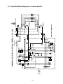
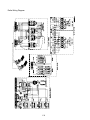
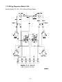
1.13 Simplified Wiring Diagrams, Common Electric 1-21
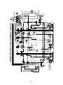
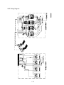
1.14 Wiring Diagrams, Main 1-26
1.15 Wiring Diagrams, Basket Lifts 1-32
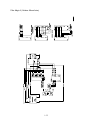
1.16 Wiring Diagrams, Filtration Systems 1-34
CHAPTER 2 – PARTS LIST 2-1
2.1 Accessories 2-1
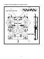
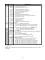
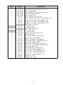
2.2 Basket Lift Assemblies and Component Parts 2-2
2.3 Cabinet Assemblies and Component Parts 2-4
2.4 Casters, Legs and Associated Hardware 2-12
2.5 Component Box Assemblies and Associated Hardware
2-14
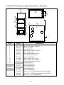
2.6 Control Panels Assemblies, Doors, and Related Components
2-15
2.7 Controller Assemblies
2-17
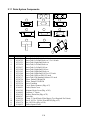
2.8 Electrical Components 2-18
2.9 Filter Base/Pan Assemblies
2-25
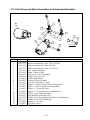
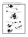
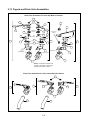
2.10 Filter Pump and Motor Assemblies and Associated Hardware 2-33
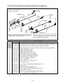
2.11 Drain System Components
2-38
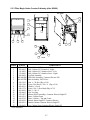
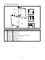
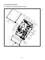
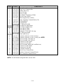
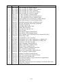
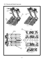
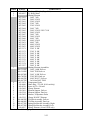
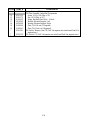
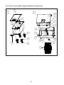
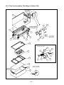
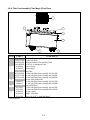
2.12 Filtration System Components 2-39
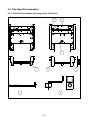
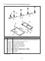
2.13 Frypot Assemblies and Drain Valve Components 2-42
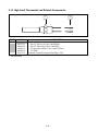
2.14 High-Limit Thermostat and Related Components
2-44

1-1
H14/H17/H22 SERIES ELECTRIC FRYERS
CHAPTER 1: SERVICE PROCEDURES
1.1 General
Before performing any maintenance on your Frymaster fryer, you must disconnect the electrical
power supply.
When electrical wires are disconnected, it is recommended that they be marked in such a way as to
facilitate re-assembly.
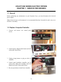
1.2 Replace Computer/Controller
1. Unscrew and remove two control panel
screws.
2. Control panel is hinged at the bottom and will
swing open from the top.
3. Unplug wiring harness at plug on back of
controller.
4. Control panel including controller can be
removed by lifting the assembly from the
hinged slots in the control panel frame.
5. Reverse procedures to install new controller.

1-2
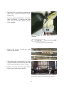
1.3 Replace Interface Board
1. Unplug all power cords. Perform Procedure 1.2, Steps 1-4, Replace Computer/Controller.
2. Unplug wire harness from the interface
board. Remove all wiring from the terminals
of the interface board, ensuring that each wire
is marked for reattachment.
3. Remove the screws securing the control panel
frame. Set the control panel frame/screws
aside.
4. Remove the screws securing the top cap. Set
the top cap/screws aside.
5. Remove the screws securing the component
box. Set the component box drop down
enough so that the wire harness can be
unplugged from the back of the assembly.
6. Remove the nuts from each corner of the
interface board and slide the board from the
studs. Ensure that standoffs remain in place
on studs, prior to installing new interface
board. Install the new interface board by
reversing the previous procedures. Ensure
that wire harnesses are connected to back of
interface board prior to securing component
box. Also ensure that wiring and wire
harnesses are connected to the proper
terminals.
Screws securin
g
control panel frame
Wire harness/connector
Nuts securing interface board

1-3
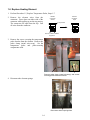
1.4 Replace Transformer
1. Unplug all power cords. Perform Procedure 1.2, Steps 1-4, Replace Computer/Controller.
2. Remove all wiring from the terminals of the
transformer to be replaced.
3. Remove the screws that secure the
transformer to the component box.
4. Install the new transformer by reversing the
preceding procedures. Make sure you
reconnect the wiring to the proper terminals
and the harnesses to the correct connectors.
1.5 Replace Temperature Probe
1. Unplug fryer from the electrical source.
2. Drain the cooking oil from the frypot.
3. Remove the fryer from the exhaust hood to gain access to the rear of the fryer.
4. Remove the screws from the top, center and
bottom back covers. Set the covers and
screws aside.
5. Remove the screws securing the tilt housing
cover. Set the tilt housing cover aside.
Screws securing transformers
Screws securing back covers and tilt housing

1-4
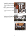
6. Disconnect the wire harness containing the
probe wiring. It may be necessary to remove
the wire ties.
7. Use a pin-pusher (P/N 806-4855 or P/N 807-
0928—see Section 1.7) to remove the probe
wires from the connector. Mark each wire
for re-assembly.
8. Remove the screw(s) securing the probe
bracket to the element.
9. Thread the probe wire through the hole in the
tilt plate assembly and remove the probe and
the securing components from the element.
10. Remove the probe from the probe bracket.
Place the new probe into the bracket.
Thread probe wire through hole in tilt plate assembly,
then remove probe and components from element.
Use a pin-pusher to remove probe wires from
connector
Pin-pusher (Frymaster P/N 806-4855)

1-5
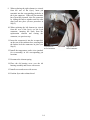
11. Place the new temperature probe assembly
onto the element and secure with the screws
removed earlier. Clip the probe onto the rear
of the element. The temperature probe
assembly should be oriented in the same
manner as the probe being replaced.
12. Thread the probe wires into the harness
connector as removed in Step 7.
13. Lower the element into the frypot.
14. Place the tilt housing cover over the tilt
housing assembly and secure with screws
15. Install the top, center and bottom back covers
and secure with screws.
Secure probe to
element with metal
wire-wrap
New probe assembly
properly installed in
tilt plate
Tilt housing cover in place

1-6
1.6 Replace Heating Element
1. Perform Procedure 1.5, Replace Temperature Probe, Steps 1-7.
2. Remove the element wires from the
connector. Press down on either side of the
connector while pulling up on the top portion.
The connector will open from the top. Pull
all wires from the connector.
3. Remove the screws securing the temperature
probe bracket from the element. Remove the
probe clamp (metal wire-wrap). Set the
temperature probe and probe-securing
components aside.
4. Disconnect the element springs.
Top Portion
Harness
Connector
Closed
Harness
Connector
Open
Push in on tabs to release
top portion
Remove probe clamp (metal wire-wrap), and screws
securing probe bracket to element.
Disconnect element springs here

1-7
5. Remove the element mounting-screws and
pull the element out of the frypot (split-vats).
On full-vat elements, remove the element
clamps and hardware before removing
mounting-screws and nuts on the defective
element.
6. Install the replacement element in the frypot
and secure with the mounting screws
removed in Step 5.
7. Re-install the temperature probe and probe-
securing components onto the replacement
element.
8. Route the element leads (terminals) to the
rear of the fryer. Ensure that chafing guards
are in place to prevent wire chafing while
raising and lowering elements.
Front
Back
Element mounting-screws and nuts. (Inset Photo-
back of tilt plate)
Proper element-wire routing is essential to prevent
wire chafing while raising and lowering elements.
Chafing guards on cabinet edges also help prevent
wire chafing while raising and lowering elements.

1-8
9. When replacing the right element (as viewed
from the rear of the fryer), insert pin
terminals into the corresponding pin-holes in
the 6-pin connector. When all pin terminals
have been fully inserted, close the connector
by sliding the halves together until the tabs
snap back into place (reverse procedure in
Step 2).
10. When replacing the left element (as viewed
from the rear of the fryer), use the 9-pin
connector, inserting the leads from the
replacement element and closing the
connector, see previous step.
11. Insert the connector(s) into the receptacle(s)
on the rear of the contactor box, ensuring that
the latches lock the connectors in place (see
Step 9).
12. Install the temperature probe wires (marked
for re-assembly) in the corresponding pin
locations.
13. Reconnect the element spring.
14. Place the tilt housing cover over the tilt
housing assembly and secure with screws.
15. Install covers and secure with screws.
16. Position fryer under exhaust hood.
Left Element—
9-Pin Connector
Right Element—
6-Pin Connector

1-9
1.7 Replace High-Limit
1. Perform Procedure 1.5, Replace Temperature
Probe, Steps 1-4.
2. Disconnect the wire harness containing the
high-limit wires.
3. Use a pin-pusher (P/N 806-4855 or P/N 807-
0928) to remove the two high-limit wires
from the wire harness connector. For split-
pot fryers, remove only the wires for the
high-limit to be replaced. Mark each wire for
re-assembly.
4. Remove the high-limit from the frypot using
an open-end wrench or other suitable tool.
5. Apply Loc-Tite PST 567 sealant to the
replacement high-limit threads.
6. Screw the replacement high-limit into the
frypot and tighten securely. DO NOT
OVERTIGHTEN.
7. Insert the replacement high-limit wires into
the proper pin-holes in the connector. The
same two pin-holes from which the defective
high-limit wires were removed.
8. Reconnect the wire harness connector.
9. Install and secure the back covers.
10. Position the fryer under the exhaust hood.
Proper element-wire routing is essential to prevent
wire chafing while raising and lowering elements.
Pin Pusher— P/N 807-0928
Place wrench here when removing and installing
high-limit.

1-10
1.8 Replace Frypot
1. Perform Procedure 1.5, Replace Temperature Probe, Steps 1-7.
2. Perform Procedure 1.2, Replace Computer/Controller, Steps 1-6.
3. Disconnect the wire harness containing the high-limit wires.
4. Use a pin-pusher to remove the high-limit wires from the wire harness connector.
5. Remove the high-limit from the frypot.
6. Disconnect the wire-harnesses connected to the contactor box.
7. Remove the screws securing the capping piece from the fryer. Remove the capping piece and set
aside. It may be necessary to remove the wiring covers from the front of the contactor box.
8. If the fryer has a built-in filtration system, remove all the plumbing from the frypot, including
rear-flush and square-drain plumbing.
9. Remove the screws securing the frypot to the front frame of the fryer.
10. Carefully lift the frypot from the cabinet.
11. Remove the drain valve from the old frypot and install on the new frypot.
12. Apply Loc-Tite Sealant PST 567 to the high-limit threads. Install the high-limit into the new
frypot.
13. Disconnect the tilt plate springs from the old frypot.
14. Remove the securing screws from the tilt plate. Lift the tilt plate/heating element assembly from
the old frypot and install on the new frypot.
15. Follow the preceding steps in reverse to install the new frypot into the fryer.
16. NOTE: Apply Loc-Tite Sealant PST 567 to all pipefittings prior to installation.
1.9 Replace Contactor
1. Perform Procedure 1.4, Replace Temperature Probe, Steps 1-3.
2. Remove the screws securing the bottom and center rear access covers. Set the screws and covers
aside.

1-11
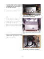
3. If present, remove the screws securing the
wiring covers to the front of the contactor box
(optional on old-style contactor boxes). Set
the screws and covers aside.
4. Disconnect the wire harnesses from the front
and rear of the contactor box.
5. Remove the screws securing the contactor
box to the bottom frame of the fryer.
6. Pull the contactor box through the access
opening in the rear of the fryer.
7. Remove the screws securing the contactor
box cover. Set the screws and covers aside.
8. Remove all wiring connected to the contactor
terminals inside the contactor box. Mark
each wire for re-assembly.
Screws securing wire cover to contactor box
(optional on old-style contactor boxes)
Screw location securing contactor box to bottom
frame
Mark each wire for re-assembly, then remove all
wiring connected to the contactor(s) to be replaced.

1-12
9. Remove the contactor mounting screws and
remove the contactor.
10. Install the new contactor and connect the
wiring removed in Step 8.
11. Install the contactor box by following the
previous steps in reverse order.
1.10 Built-in Filter System Service Procedures
Filtration Problem Resolution
One of the most common errors is placing the filter paper on the bottom of the filter pan rather than
over the filter screen.
CAUTION
Ensure that filter screen is in place prior to filter paper placement and filter pump
operation. Improper screen placement is the major cause of filter system
malfunction.
Whenever the complaint is “the pump is running, but no oil is being filtered,” check the installation
of the filter paper, and ensure that the correct size is being used. While you are checking the filter
paper, verify that the O-ring on the bottom of the filter pan is present and in good condition. A
missing or worn O-ring allows the pump to take in air and decreases its efficiency. Also, oil leaks
on the floor each time a vat is drained.
Contactor mounting screws
Mercury Contactor
Latching Contactor

1-13
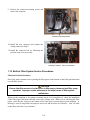
If the pump motor overheats, the thermal overload will trip and the motor will not start until it is
reset. If the pump motor does not start, press the red reset switch (button) located on the rear of the
motor.
If the pump starts after resetting the thermal
overload switch, then something is causing the
motor to overheat. A major cause of overheating
is when several frypots are filtered sequentially,
thus overheating the pump and motor. Allow the
pump motor to cool at least 30 minutes before
resuming operation.
Pump overheating can be caused by:
• Solidified shortening in the pan or filter
lines,
or
• Attempting to filter unheated oil or
shortening.
Cold oil and shortening are more viscous,
causing the pump motor to load up and overheat.
If the motor runs but the pump does not, there is
a blockage in the pump. Incorrectly sized or
installed paper/pads will allow food particles and
sediment to pass through the filter pan and into
the pump. When sediment enters the pump, the
gears bind, causing the motor to overload, again
tripping the thermal overload. Shortening that
has solidified in the pump will also cause it to
seize, with the same result.
A pump seized by debris or hard shortening can
usually be freed by manually moving the gears
with a screwdriver or other instrument.
Disconnect power to the filter system.
Remove the input plumbing from the pump.
Sediment Particle
Oil Flow
Up for reverse
Down for forward
Sediment Particle
Reset switch location: Old-style FPIII
Reset switch location: New-style FPIII
Freeing a seized pump.

1-14
Use a screwdriver to manually turn the gears, in which:
● Turning the pump gears in reverse will release a hard particle.
● Turning the pump gears forward will push softer objects and solid shortening through the
pump and allow free movement of the gears.
Incorrectly sized or installed paper/pads will also allow food particles and sediment to pass through
and clog the suction tube on the bottom of the filter carriage. Particles large enough to block the
suction tube may indicate that the crumb tray is not being used.
Pan blockage can also occur if shortening is left in the pan and allowed to solidify. The heater strip
on the suction tube is designed to prevent residual shortening from solidifying in the tube. Heater
strips do not prevent residual shortening from solidifying in the pan.
Blockage removal can be accomplished by forcing the item out with an auger or drain snake.
Compressed air or other pressurized gases should not be used to force out the blockage.
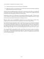
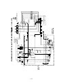
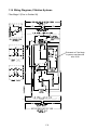
For FootPrint III systems built before October, 1999, all heater tapes are wired directly into the line
VAC source (see wiring diagram, page 1-15). They remain energized as long as the unit is plugged
in. In systems built in October, 1999 and later, oil return line heater tapes have been eliminated. In
these units, the only heater tape used is on the suction tube and pump. This tape is still wired
directly into the line voltage. A pair of vacuum-breaking solenoids is wired into the 24 VAC circuit.
The redesigned FPIII is distinguished from the original design by the absence of casters on the filter
base assembly. The redesign incorporated an improved oil return system that allows oil/shortening
to drain back to the filter pan when the filter system is turned off, eliminating the need for most
heated oil return components.

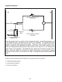
1-15
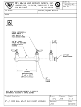
M
Pump Relay
Coil
Micro-switches
Pump Motor Switch
Pump Motor
Solenoids
(Redesigned Models Only)
24
VAC
Line
VAC
FootPrint III Wiring Diagram
All Heater Tapes (Original and
Redesigned Models)
(Heater Tapes have been removed from
return lines in Redesigned Models)
Operation of the redesigned FP-III system is the same as for the original design.
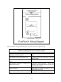
ORIGINAL VS REDESIGNED FP-III FILTRATION SYSTEM
Original System Redesigned System
Return lines and manifolds wrapped with silicone
strip heaters and aluminum tape.
No heater strips or aluminum tape on return
lines.
Filter base assembly connected to unit with a
black, heated return hose beneath the filter.
Non-heated Teflon hose with a swivel joint
connects the filter base assembly to the unit
above the filter.
Filter base assembly equipped with swivel
casters.
Filter base assembly has no casters.
Operator-removable filter base assembly. (Filter
base assembly stop-locks in cabinet can be
rotated to remove tray.)
Filter base assembly is not removable except by
a qualified service technician. (Filter base
assembly stop-locks fitted with a screw and nut
to prevent filter removal.)
Oil/shortening remains in return lines when filter
system is turned off.
Oil/shortening drains back to the filter pan when
filter system is turned off, leaving no oil or
shortening in return lines.
Return drain-manifolds are constructed with pipe
nipples, elbows and other plumbing components.
Return drain manifolds are one-piece with an in-
line solenoid valve to facilitate drain to filter pan.

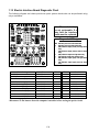
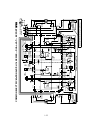
1-16
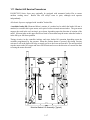
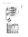
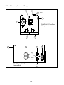
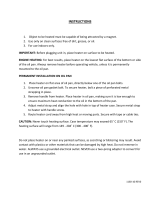
Microswitches
Relay Contacts
Pump Motor
Pump Relay Coil
Transformer
24VAC
M
Pump Heater
Line VAC
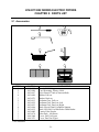
Filter Magic Simplified Wiring Diagram
Page is loading ...
Page is loading ...
Page is loading ...
Page is loading ...
Page is loading ...
Page is loading ...
Page is loading ...
Page is loading ...
Page is loading ...
Page is loading ...
Page is loading ...
Page is loading ...
Page is loading ...
Page is loading ...
Page is loading ...
Page is loading ...
Page is loading ...
Page is loading ...
Page is loading ...
Page is loading ...
Page is loading ...
Page is loading ...
Page is loading ...
Page is loading ...
Page is loading ...
Page is loading ...
Page is loading ...
Page is loading ...
Page is loading ...
Page is loading ...
Page is loading ...
Page is loading ...
Page is loading ...
Page is loading ...
Page is loading ...
Page is loading ...
Page is loading ...
Page is loading ...
Page is loading ...
Page is loading ...
Page is loading ...
Page is loading ...
Page is loading ...
Page is loading ...
Page is loading ...
Page is loading ...
Page is loading ...
Page is loading ...
Page is loading ...
Page is loading ...
Page is loading ...
Page is loading ...
Page is loading ...
Page is loading ...
Page is loading ...
Page is loading ...
Page is loading ...
Page is loading ...
Page is loading ...
Page is loading ...
Page is loading ...
Page is loading ...
Page is loading ...
Page is loading ...
Page is loading ...
Page is loading ...
-
 1
1
-
 2
2
-
 3
3
-
 4
4
-
 5
5
-
 6
6
-
 7
7
-
 8
8
-
 9
9
-
 10
10
-
 11
11
-
 12
12
-
 13
13
-
 14
14
-
 15
15
-
 16
16
-
 17
17
-
 18
18
-
 19
19
-
 20
20
-
 21
21
-
 22
22
-
 23
23
-
 24
24
-
 25
25
-
 26
26
-
 27
27
-
 28
28
-
 29
29
-
 30
30
-
 31
31
-
 32
32
-
 33
33
-
 34
34
-
 35
35
-
 36
36
-
 37
37
-
 38
38
-
 39
39
-
 40
40
-
 41
41
-
 42
42
-
 43
43
-
 44
44
-
 45
45
-
 46
46
-
 47
47
-
 48
48
-
 49
49
-
 50
50
-
 51
51
-
 52
52
-
 53
53
-
 54
54
-
 55
55
-
 56
56
-
 57
57
-
 58
58
-
 59
59
-
 60
60
-
 61
61
-
 62
62
-
 63
63
-
 64
64
-
 65
65
-
 66
66
-
 67
67
-
 68
68
-
 69
69
-
 70
70
-
 71
71
-
 72
72
-
 73
73
-
 74
74
-
 75
75
-
 76
76
-
 77
77
-
 78
78
-
 79
79
-
 80
80
-
 81
81
-
 82
82
-
 83
83
-
 84
84
-
 85
85
-
 86
86


Frymaster H14 User manual
- Category
- Deep fryers
- Type
- User manual
Ask a question and I''ll find the answer in the document
Finding information in a document is now easier with AI
Related papers
-
 Frymaster FPH17 User manual
-
 Frymaster 2836 User manual
-
 Frymaster 2836 Series Electric Fryers User manual
-
 Frymaster McDonald's H14 User manual
-
 Frymaster 8196428 User manual
-
 Frymaster H14/17/22 (Common Electric) Operating instructions
-
 Frymaster FPPH17 User manual
-
 Frymaster H14SC User manual
-
 Frymaster e4 User manual
-
 Frymaster e4 User manual


Other documents
-
CyberPower CRA60002 Quick start guide
-
 T & S Brass & Bronze Works 002832-40 Datasheet
-
 KAT'S 4270099 Owner's manual
-
Black Box RMT625A Datasheet
-
ESAB 60 AMP Troubleshooting instruction
-
Scotsman Changing the Control Board from its Original Configuration to the AutoSentry System - 17-2813-01 Operating instructions
-
Bennett Marine ES2000 User manual
-
 Dean & Deluca BK1814 User manual
-
Weatherables AWCP-LVNEPTUNEKIT-4 Installation guide
-
Ronix RH-1376 User manual


