Page is loading ...

Table of Contents
Cover photo may show optional equipment not supplied
with standard unit.
For an Operator’s Manual and Decal Kit in French
Language, please see your Kubota dealer.
Read the Operator’s Manual entirely. When you see this symbol,
the subsequent instructions and warnings are serious - follow
without exception. Your life and the lives of others depend on it!
!
70586
6-Way Dozer Blade
AP-DZ3084 & AP-DZ3096
301-587MK
Operator’s Manual
Printed 4/10/19

4/10/19AP-DZ3084 & AP-DZ3096 6-Way Dozer Blade 301-587MK
Machine Identification
Record your machine details in the log below. If you replace this manual, be sure to transfer this information to the new
manual.
If you, or the dealer, have added Options not originally ordered with the machine, or removed Options that were
originally ordered, the weights and measurements are no longer accurate for your machine. Update the record by
adding the machine weight and measurements provided in the Specifications & Capacities Section of this manual with
the Option(s) weight and measurements.
Dealer Contact Information
Model Number
Serial Number
Machine Height
Machine Length
Machine Width
Machine Weight
Delivery Date
First Operation
Accessories
Name:
Street:
City/State:
Telephone:
Email:
WARNING: Cancer and reproductive harm - www.P65Warnings.ca.gov
!
California Proposition 65

Table of Contents
© Copyright 2019 All rights Reserved
Kubota provides this publication “as is” without warranty of any kind, either expressed or implied. While every precaution has been taken in the preparation of this manual, Kubota
assumes no responsibility for errors or omissions. Neither is any liability assumed for damages resulting from the use of the information contained herein. Kubota reserves the right
to revise and improve its products as it sees fit. This publication describes the state of this product at the time of its publication, and may not reflect the product in the future.
Kubota is a registered trademark.
All other brands and product names are trademarks or registered trademarks of their respective holders.
Printed in the United States of America.
4/10/19
AP-DZ3084 & AP-DZ3096 6-Way Dozer Blade 301-587MK
Table of Contents
Important Safety Information . . . . . . . . . . . . . 1
Safety at All Times . . . . . . . . . . . . . . . . . . . . . . . . . 1
Look for the Safety Alert Symbol . . . . . . . . . . . . . . . 1
Safety Labels . . . . . . . . . . . . . . . . . . . . . . . . . . . . . 6
Introduction . . . . . . . . . . . . . . . . . . . . . . . . . . . 8
Application . . . . . . . . . . . . . . . . . . . . . . . . . . . . . . . 8
Using This Manual . . . . . . . . . . . . . . . . . . . . . . . . . 8
Terminology . . . . . . . . . . . . . . . . . . . . . . . . . . . . . 8
Definitions . . . . . . . . . . . . . . . . . . . . . . . . . . . . . . 8
Owner Assistance . . . . . . . . . . . . . . . . . . . . . . . . . . 8
Serial Number . . . . . . . . . . . . . . . . . . . . . . . . . . . 8
Section 1: Assembly & Set-up . . . . . . . . . . . . 9
Skid Steer Requirements . . . . . . . . . . . . . . . . . . . . 9
Torque Requirements . . . . . . . . . . . . . . . . . . . . . . . 9
Before You Start . . . . . . . . . . . . . . . . . . . . . . . . . . . 9
Skid Steer Shutdown Procedure . . . . . . . . . . . . . . . 9
Spring Hose Holder Assembly . . . . . . . . . . . . . . . 10
Hook-up Dozer Blade . . . . . . . . . . . . . . . . . . . . . . 10
Hydraulic Hose Hook-up . . . . . . . . . . . . . . . . . . . . 11
Electrical Hook-up . . . . . . . . . . . . . . . . . . . . . . . . . 11
Tilt Control Hardware . . . . . . . . . . . . . . . . . . . . . . 12
Purge Hydraulic System . . . . . . . . . . . . . . . . . . . . 12
Equipment Clearances . . . . . . . . . . . . . . . . . . . . . 13
Section 2: Optional Equipment Set-up . . . . . 14
Electrical Control Harness (Optional) . . . . . . . . . . 14
HD30 14 Pin Plug Control Harness . . . . . . . . . . . . 14
Kubota 14 Pin Plug Control Harness . . . . . . . . . 14
John Deere 14 Pin Plug Control Harness . . . . . 14
John Deere EH14 Pin Plug Control Harness . . . 14
2-Pin Plug Control Harness . . . . . . . . . . . . . . . . 15
Battery Connect Control Harness . . . . . . . . . . . 15
Section 3: Adjustments . . . . . . . . . . . . . . . . . 16
Tilt Control . . . . . . . . . . . . . . . . . . . . . . . . . . . . . . 16
Tilt Control Fully Locked . . . . . . . . . . . . . . . . . . 16
Tilt Control Fully Unlocked . . . . . . . . . . . . . . . . . 16
Tilt Control Set for Clockwise Tilting . . . . . . . . . 16
Tilt Control Set for Counterclockwise Tilting . . . . 16
Section 4: Operating Procedures . . . . . . . . . 17
Operating Checklist . . . . . . . . . . . . . . . . . . . . . . . . 17
General Safety Information . . . . . . . . . . . . . . . . . . 17
Equipment Inspection . . . . . . . . . . . . . . . . . . . . . . 18
Transporting . . . . . . . . . . . . . . . . . . . . . . . . . . . . . 18
Operating Guidelines . . . . . . . . . . . . . . . . . . . . . . . 18
Operating Functions . . . . . . . . . . . . . . . . . . . . . . . 19
Tilt Top of Blade Forward or Backward . . . . . . . 19
Angle Blade Left or Right . . . . . . . . . . . . . . . . . . 19
Tilt Blade Clockwise or Counterclockwise . . . . . 19
Control Harness with 14-pin plug . . . . . . . . . . . . 19
Control Harness with 2-pin plug or 2 eyelets. . . . 19
Gradiometer . . . . . . . . . . . . . . . . . . . . . . . . . . . . 19
Operating the Dozer Blade . . . . . . . . . . . . . . . . . . 20
Scraping and/or Leveling . . . . . . . . . . . . . . . . . . 20
Building a Ditch or Berm . . . . . . . . . . . . . . . . . . . 20
Filling Holes or Undulations. . . . . . . . . . . . . . . . . 20
Remove and Pile Debris or Trees . . . . . . . . . . . . . 20
Unhook Dozer Blade . . . . . . . . . . . . . . . . . . . . . . . 20
General Operating Instructions . . . . . . . . . . . . . . . 21
Section 5: Maintenance & Lubrication . . . . . 22
General Maintenance Information . . . . . . . . . . . . . 22
Hydraulic System . . . . . . . . . . . . . . . . . . . . . . . . . 22
Cutting Edges & Wear Edge . . . . . . . . . . . . . . . . . 22
Preparation Instructions . . . . . . . . . . . . . . . . . . . 22
Removal & Assembly of Cutting Edges . . . . . . . 23
Wear Edge Removal & Assembly . . . . . . . . . . . . 24
Remove Support Block . . . . . . . . . . . . . . . . . . . . 24
Guide Plates . . . . . . . . . . . . . . . . . . . . . . . . . . . . . 25
Long-Term Storage . . . . . . . . . . . . . . . . . . . . . . . . 26
Lubrication Points . . . . . . . . . . . . . . . . . . . . . . . . . 27
Hydraulic Cylinder Pivot Pins . . . . . . . . . . . . . . . 27
Blade Tilt Pin . . . . . . . . . . . . . . . . . . . . . . . . . . . 27
King Pin . . . . . . . . . . . . . . . . . . . . . . . . . . . . . . . 27
Section 6: Specifications & Capacities . . . . . 28
Section 7: Features and Benefits . . . . . . . . . 30
Section 8: Troubleshooting . . . . . . . . . . . . . . 31
Section 9: Torque Values Chart . . . . . . . . . . . 32
Section 10: Warranty & Legal Disclaimer . . . 34

Table of Contents Continued
Parts Manual QR Locator
The QR (Quick Reference) code on the
cover and to the left will take you to the
Parts Manual for this equipment.
Download the appropriate App on your
smart phone, open the App, point your
phone on the QR code and take a picture.
Dealer QR Locator
The QR code on the left will
link you to available dealers
for Kubota products. Refer to
Parts Manual QR Locator on
this page for detailed
instructions.
Table of Contents
4/10/19AP-DZ3084 & AP-DZ3096 6-Way Dozer Blade 301-587MK
See previous page for Table of Contents.

Important Safety Information
4/10/19
1
Important Safety Information
Listed below are common practices that may or may not be applicable to the products
described in this manual.
Safety at All Times
Careful operation is your best
assurance against an accident.
All operators, no matter how much
experience they may have, should
carefully read this manual and
other related manuals, or have the
manuals read to them, before
operating the power machine and
this attachment.
Thoroughly read and understand
the “Safety Label” section. Read
all instructions noted on them.
Do not operate the equipment
while under the influence of drugs
or alcohol as they impair the ability
to safely and properly operate the
equipment.
Operator should be familiar with all
functions of the skid steer and
attachment and be able to handle
emergencies quickly.
Make sure all guards and shields
appropriate for the operation are in
place and secured before
operating the attachment.
Keep all bystanders away from
equipment and work area.
Start skid steer from the driver’s
seat with steering levers and
hydraulic controls in neutral.
Operate skid steer and controls
from the driver’s seat only.
Never dismount from a moving
skid steer or leave skid steer
unattended with engine running.
Do not allow anyone to stand
between attachment and skid
steer while hooking-up.
Keep hands, feet, and clothing
away from power-driven parts.
While transporting and operating
equipment, watch out for objects
overhead and along side such as
fences, trees, buildings, wires, etc.
Store attachment in an area where
children normally do not play.
When needed, secure attachment
against falling with support blocks.
OFF
R
EM
O
VE
Safety Precautions for
Children
Tragedy can occur if the operator
is not alert to the presence of
children. Children generally are
attracted to attachments and their
work.
Never assume children will remain
where you last saw them.
Keep children out of the work area
and under the watchful eye of a
responsible adult.
Be alert and shut the attachment
and skid steer/track loader down if
children enter the work area.
Never carry children on the power
machine or attachment. There is
not a safe place for them to ride.
They may fall off and be run over
or interfere with the control of the
power machine.
Never allow children to operate the
power machine, even under adult
supervision.
Never allow children to play on the
power machine or attachment.
Use extra caution when backing
up. Before the power machine
starts to move, look down and
behind to make sure the area is
clear.
Skid Steer Shutdown
And Storage
Reduce engine speed and shut-off
all power to the attachment.
Park on solid, level ground and
lower attachment until it is flat on
the ground or support blocks.
Turn off engine, and remove
switch key to prevent unauthorized
starting.
Relieve all hydraulic pressures.
If included, raise seat bar and
move controls until both lock.
Wait for all components to stop
before leaving operator’s seat.
Use steps, grab-handles and
anti-slip surfaces when stepping
on and off the skid steer.
Detach and store attachment in an
area where children normally do
not play. Secure attachment by
using blocks and supports.
Look for the Safety Alert Symbol
The SAFETY ALERT SYMBOL indicates there is a
potential hazard to personal safety involved and extra
safety precaution must be taken. When you see this
symbol, be alert and carefully read the message that
follows it. In addition to design and configuration of
equipment, hazard control, and accident prevention are
dependent upon the awareness, concern, prudence, and
proper training of personnel involved in the operation,
transport, maintenance, and storage of equipment.
!
Be Aware of
Signal Words
A signal word designates a degree or
level of hazard seriousness. The
signal words are:
Indicates a hazardous situation that, if
not avoided, will result in death or
serious injury.
Indicates a hazardous situation that, if
not avoided, could result in death or
serious injury.
Indicates a hazardous situation that, if
not avoided, may result in minor or
moderate injury.
WARNING
CAUTION
!
!
DANGER
!

Important Safety Information
4/10/19
2
Dig Safe - Avoid
Underground Utilities
USA: Call 811
CAN: digsafecanada.ca
Always contact your local utility
companies (electrical, telephone,
gas, water, sewer, and others)
before digging so that they may
mark the location of any
underground services in the
area.
Be sure to ask how close you can
work to the marks they
positioned.
Listed below are common practices that may or may not be applicable to the products
described in this manual.
Transport Safely
Comply with federal, state, and local
laws.
Use towing vehicle and trailer of
adequate size and capacity. Secure
equipment towed on a trailer with
chocks, tie downs, and chains.
Sudden braking can cause a towed
trailer to swerve and upset. Reduce
speed if towed trailer is not equipped
with brakes.
Avoid contact with any overhead
utility lines or electrically charged
conductors.
Always drive with load on end of
loader arms low to the ground.
Always drive straight up and down
steep inclines with heavy end of skid
steer on the “uphill” side.
Engage park brake when stopped on
an incline.
Maximum transport speed for an
attached equipment is 20 mph. DO
NOT EXCEED. Never travel at a
speed which does not allow
adequate control of steering and
stopping. Some rough terrains
require a slower speed.
As a guideline, use the following
maximum speed weight ratios for
attached equipment:
20 mph when weight of attached
equipment is less than or equal to
the weight of machine towing the
equipment.
10 mph when weight of attached
equipment exceeds weight of
machine towing equipment but not
more than double the weight.
IMPORTANT: Do not tow a load that
is more than double the weight of the
vehicle towing the load.
Practice Safe Maintenance
Understand procedure before doing
work. Refer to the Operator’s Manual
for additional information.
Work on a level surface in a clean
dry area that is well-lit.
Lower attachment to the ground and
follow all shutdown procedures
before leaving the operator’s seat to
perform maintenance.
Do not work under any hydraulic
supported equipment. It can settle,
suddenly leak down, or be lowered
accidentally. If it is necessary to work
under the equipment, securely
support it with stands or suitable
blocking beforehand.
Use properly grounded electrical
outlets and tools.
Use correct tools and equipment for
the job that are in good condition.
Allow equipment to cool before
working on it.
Disconnect battery ground cable (-)
before servicing or adjusting
electrical systems or before welding
on equipment.
Inspect all parts. Make certain parts
are in good condition & installed
properly.
Replace parts on this attachment
with genuine Kubota parts only. Do
not alter this attachment in a way
which will adversely affect its
performance.
Do not grease or oil attachment
while it is in operation.
Remove buildup of grease, oil, or
debris.
Always make sure any material and
waste products from the repair and
maintenance of the attachment are
properly collected and disposed.
Remove all tools and unused parts
from the equipment before
operation.
Tire Safety
Tire changing can be dangerous
and must be performed by
trained personnel using the
correct tools and equipment.
Always maintain correct tire
pressure. Do not inflate tires
above recommended pressures
shown in the Operator’s Manual.
When inflating tires, use a clip-on
chuck and extension hose long
enough to allow you to stand to
one side and NOT in front of or
over the tire assembly. Use a
safety cage if available.
Securely support the attachment
when changing a wheel.
When removing and installing
wheels, use wheel handling
equipment adequate for the
weight involved.
Make sure wheel bolts have been
tightened to the specified torque.

Important Safety Information
4/10/19
3
These are common practices that may or may not be applicable to the products described in
this manual.
Prepare for Emergencies
Be prepared if a fire starts.
Keep a first aid kit and fire
extinguisher handy.
Keep emergency numbers for
doctor, ambulance, hospital, and
fire department near phone.
911
Avoid High
Pressure Fluids Hazard
Escaping fluid under pressure
can penetrate the skin causing
serious injury.
Relieve all residual pressure
before disconnecting hydraulic
lines or performing work on the
hydraulic system.
Make sure all hydraulic fluid
connections are tight and all
hydraulic hoses and lines are in
good condition before applying
pressure to the system.
Use a piece of paper or
cardboard, NOT BODY PARTS,
to check for suspected leaks.
Wear protective gloves and
safety glasses or goggles when
working with hydraulic systems.
DO NOT DELAY. If an accident
occurs, see a doctor familiar with
this type of injury immediately.
Any fluid injected into the skin or
eyes must be treated
within a few hours or
gangrene may
result.
Wear Personal Protective
Equipment (PPE)
Wear protective clothing and
equipment appropriate for the job
such as safety shoes, safety
glasses, hard hat, and ear plugs.
Clothing should fit snug without
fringes and pull strings to avoid
entanglement with moving parts.
Prolonged exposure to loud noise
can cause hearing impairment or
hearing loss. Wear suitable
hearing protection such as
earmuffs or earplugs.
Operating equipment safely
requires the operator’s full
attention. Avoid wearing
headphones while operating
equipment.
Use Safety
Lights and Devices
Slow moving tractors, skid steers,
and self-propelled machines can
create a hazard when driven on
public roads. They are difficult to
see, especially at night. Use the
Slow Moving Vehicle (SMV) sign
when on public roads.
Flashing warning lights and turn
signals are recommended
whenever driving on public roads.
Keep Riders Off
Machinery
Never carry riders on skid steer
or attachment.
Riders obstruct operator’s view
and interfere with the control of
the power machine.
Riders can be struck by objects
or thrown from the equipment.
Never use skid steer or
attachment to lift or transport
riders.
Use Seat Belt and ROPS
Kubota recommends the use of a
CAB or roll-over-protective-
structures (ROPS) and seat belt
in almost all power machines.
Combination of a CAB or ROPS
and seat belt will reduce the risk
of serious injury or death if the
power machine should be upset.
If ROPS is in the locked-up
position, fasten seat belt snugly
and securely to help protect
against serious injury or death
from falling and machine
overturn.

Important Safety Information
4/10/19
4
Avoid crystalline Silica
(quartz) Dust
Because crystalline silica is a basic
component of sand and granite,
many activities at construction sites
produce dust containing crystalline
silica. Trenching, sawing, and boring
of material containing crystalline
silica can produce dust containing
crystalline silica particles. This dust
can cause serious injury to the
lungs (silicosis).
There are guidelines which should
be followed if crystalline silica
(quartz) is present in the dust.
Be aware of and follow OSHA
(or other local, State, or Federal)
guidelines for exposure to airborne
crystalline silica.
Know the work operations where
exposure to crystalline silica may
occur.
Participate in air monitoring or
training programs offered by the
employer.
Be aware of and use optional
equipment controls such as water
sprays, local exhaust ventilation,
and enclosed cabs with positive
pressure air conditioning if the
machine has such equipment.
Otherwise respirators shall be worn.
Where respirators are required, wear
a respirator approved for protection
against crystalline silica containing
dust. Do not alter respirator in any
way. Workers who use tight-fitting
respirators can not have beards/
mustaches which interfere with the
respirator seal to the face.
If possible, change into disposable
or washable work clothes at the
work site; shower and change into
clean clothing before leaving the
work site.
Do not eat, drink, use tobacco
products, or apply cosmetics in
areas where there is dust containing
crystalline silica.
Store food, drink, and personal
belongings away from the work
area.
Wash hands and face before eating,
drinking, smoking, or applying
cosmetics after leaving the exposure
area.
Listed below are common practices that may or may not be applicable to the products
described in this manual.
Handle
Chemicals Properly
Protective clothing should be
worn.
Handle all chemicals with care.
Follow instructions on container
label.
Agricultural chemicals can be
dangerous. Improper use can
seriously injure persons, animals,
plants, soil, and property.
Inhaling smoke from any type of
chemical fire is a serious health
hazard.
Store or dispose of unused
chemicals as specified by the
chemical manufacturer.

Important Safety Information
4/10/19
5
This page left blank intentionally.

6
Important Safety Information
AP-DZ3084 & AP-DZ3096 6-Way Dozer Blade 301-587MK
4/10/19
Table of Contents
Safety Labels
Your 6-Way Dozer Blade comes equipped with all safety labels
in place. They are designed to help you safely operate your
attachment. Read and follow their directions.
1. Keep all safety labels clean and legible.
2. Refer to this section for proper label placement. Replace
all damaged or missing labels. Order new labels from your
nearest Kubota dealer. To find your nearest dealer, visit
our dealer locator at www.landpride.com.
3. Some new equipment installed during repair requires
safety labels to be affixed to the replaced component as
specified by Kubota. When ordering new components make
sure the correct safety labels are included in the request.
4. Refer to this section for proper label placement.
To install new labels:
a. Clean surface area where label is to be placed.
b. Spray soapy water onto the cleaned area.
c. Peel backing from label and press label firmly onto the
surface.
d. Squeeze out air bubbles with edge of a credit card or
with a similar type of straight edge.
858-765C
Warning: General Safety Information
2-Places
70587
70587
Important Safety Information
838-112C
Danger: Pinching Hazard
2-Places


8
Introduction
AP-DZ3084 & AP-DZ3096 6-Way Dozer Blade 301-587MK
4/10/19
Table of Contents
Owner Assistance
The dealer should complete the Online Warranty
Registration at the time of purchase. This information is
necessary to provide you with quality customer service.
The parts on your 6-Way Dozer Blade have been
specially designed by Kubota/Land Pride and should only
be replaced with genuine Kubota parts. Contact a Kubota
dealer if customer service or repair parts are required.
Your Kubota dealer has trained personnel, repair parts,
and equipment needed to service the attachment.
Serial Number
For quick reference and prompt service, record model
and serial number on the inside cover page and again on
the warranty page. Always provide model number and
serial number when ordering parts and in all
correspondences with your Kubota dealer. For location of
your serial number plate, see Figure 1.
Serial Number Plate Location
Figure 1
Further Assistance
Your dealer wants you to be satisfied with your new 6-Way
Dozer Blade. If for any reason you do not understand any part
of this manual or are not satisfied with the service received, the
following actions are suggested:
1. Discuss any problems you have with your attachment
with your dealership service personnel so they can
address the problem.
2. If you are still not satisfied, seek out the owner or
general manager of the dealership, explain the
question/problem, and request assistance.
3. For further assistance write to:
Kubota by Land Pride
Service Department
1525 East North Street
P.O. Box 5060
Salina, Ks. 67402-5060
E-mail address
lpservicedept@landpride.com
IMPORTANT: A special point of information related
to the following topic. Kubota’s intention is this
information must be read & noted before continuing.
70588
Introduction
Kubota welcomes you to the growing family of new
product owners. This 6-Way Dozer Blade has been
designed with care and built by skilled workers using
quality materials. Proper assembly, maintenance, and
safe operating practices will help you get years of
satisfactory use from this product.
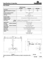
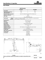
Application
The DZ30 Series 6-Way Dozer Blades are construction-
grade blades designed to meet the needs of
landscapers, construction companies, municipalities,
farmers, ranchers, homeowners, or anyone that needs to
push material from point A to point B. They are used for
backfilling, grading, landscaping, leveling, and other dirt
working tasks.
The 6-way Dozer Blade turns any skid steer or track
loader into an earth-moving machine and is available in
an 84" or 96" wide model. Both models feature a 3/8"
thick moldboard with fully boxed bracing for rugged
dependability. The 6-way blade angles up to 30 degrees
in each direction to move material left or right. It tilts
10 degrees up or down to create slopes. The hydraulic
controls simplify these adjustments. The 3-piece cutting
edges are 3/4" thick x 8" wide and are reversible and
replaceable. The user can replace the entire cutting edge
or just the high-wear, 8 1/2" long corner sections.
The hitch and angle mechanism are manufactured from
high-strength steel for years of dependable use. The
pivot pins are 3" diameter. Angle and tilt are
accomplished with strong 3.5" x 8" welded cylinders. It
also features a full length 1/2" x 4" wear bar for extended
life and durability.
See “Specifications & Capacities” on page 28 and
“Features & Benefits” on page 30 for additional
information and performance enhancing options.
Using This Manual
•
This Operator’s Manual is designed to help familiarize
you with safety, assembly, operation, adjustments,
troubleshooting, and maintenance. Read this manual
and follow the recommendations to help ensure safe
and efficient operation.
• The information contained within this manual was
current at the time of printing. Some parts may change
slightly to assure you of the best performance.
• To order a new Operator’s or Parts Manual, contact
your authorized dealer. Manuals can also be
downloaded, free-of-charge, from our website at
www.landpride.com
Terminology
“Right” or “Left” as used in this manual is determined by
facing the direction the machine will operate while in use
unless otherwise stated.
Definitions
NOTE: A special point of information that the
operator should be aware of before continuing.

9
Section 1: Assembly & Set-up
4/10/19
AP-DZ3084 & AP-DZ3096 6-Way Dozer Blade 301-587MK
Table of Contents
Skid Steer Requirements
The 6-Way Dozer Blade is designed to attach to Kubota’s
SSV65, SSV75, SVL75-2, and SVL95-2s skid steers.
WARNING
!
To avoid serious injury or death:
• Lightweight power machines may need weight added to the
rear to maintain steering control and prevent forward
tipping or side tipping caused by a heavy front load. Consult
your power machine Operator’s Manual to determine
proper weight requirements and maximum weight
limitations.
• Consult your skid steer’s manual for operating capacity,
lifting capacity, and operating specifications. Exceeding
rated capacities and specifications can result in a roll-over
or other serious hazard.
Torque Requirements
Refer to “Torque Values Chart for Common Bolt Sizes”
on page 32 to determine correct torque values when
tightening hardware.
Before You Start
WARNING
!
To avoid serious injury or death:
Allow only persons to operate this attachment who have fully
read and comprehended this manual, who are properly trained
to operate the attachment safely, and who are age 16 or older.
Serious injury or death can result from the failure to read,
understand, and follow instructions provided in this manual.
Make sure that the intended skid steer conforms to the
requirements stated above. Also, read and understand
this Operator’s Manual for your 6-Way Dozer Blade. An
understanding of how it works will aid in its assembly and
set-up.
Go through the Pre-Assembly Checklist before
assembling the Dozer Blade. To speed up your assembly
task and make the job safer, have all needed parts and
equipment readily at hand.
Section 1: Assembly & Set-up
Skid Steer Shutdown Procedure
The following are basic skid steer shutdown procedures.
Follow these procedures and any additional shutdown
procedures provided in your skid steer Operator’s
Manual before leaving the operator’s seat.
1. Reduce engine speed and shut-off all power to the
attachment.
2. Park on solid, level ground.
3. Adjust attachment level and straight (not angling).
4. Lower attachment until it is flat on the ground or on
support blocks.
5. Turn off engine, and remove switch key to prevent
unauthorized starting.
6. Relieve all hydraulic pressure to auxiliary hydraulic
lines.
7. If included, raise seat bar and move controls until
both lock.
8. Wait for all components to come to a complete stop
before leaving the operator’s seat.
9. Use steps, grab-handles and anti-slip surfaces when
stepping on and off the skid steer or attachment.
Pre-Assembly Checklist
Check Reference
Have a fork lift or loader with properly sized chains and safety
stands capable of lifting and supporting the equipment on hand.
Have a minimum of two people available during assembly.
Make sure all major components and loose
parts are shipped with the attachment.
Assembly
& Set-up
Double check to make sure all parts, fasteners,
and pins are installed in the correct location.
Refer to the Parts Manual if unsure. By double
checking, you will lessen the chance of
incorrectly using a bolt that may be needed
later.
NOTE: All assembled hardware from the
factory has been installed in the correct
location. Remember location of a part or
fastener if removed. Keep parts separated.
Operator’s
Manual
301-587MK
Parts Manual
301-587PK
Make sure working parts move freely, bolts are
tight & cotter pins are spread.
Operator’s
Manual
Make sure all grease fittings are in place and
lubricated.
Page 27
Make sure all safety labels are correctly
located and legible. Replace if damaged.
Page 6

10
Section 1: Assembly & Set-up
AP-DZ3084 & AP-DZ3096 6-Way Dozer Blade 301-587MK
4/10/19
Table of Contents
Hitch Assembly
Figure 1-1
Spring Hose Holder Assembly
Refer to Figure 1-1:
Attach spring hose holder (#13) to the hitch plate as
follows:
1. Attach spring hose holder (#13) to the hitch plate with
1/2"-13 x 1 1/2" GR5 hex bolt (#10), flat washer (#11),
and hex whiz nut (#12). Tighten hex whiz nut to the
correct torque.
2. Connect wire harness (#1) to diverter valve (#14).
3. Spread hose clip (#5) apart just enough to insert wire
harness (#1) into the clip.
4. Attach hose clip (#5) and hose clamp halves (#7) to
spring hose holder (#13) as follows:
a. Insert 5/16-18 x 3" GR5 hex head bolt (#4)
through hose clip (#5), upper hose clamp cover
plate (#6), and upper hose clamp half (#7).
b. Place hydraulic hoses (#2 & #3) in lower hose
clamp half (#7).
c. Continue to insert bolt (#4) through lower hose
clamp half (#7), lower hose clamp cover (#6), flat
washer (#8), spring hose holder (#13), and
second flat washer (#8).
d. Secure bolt (#4) in place with hex nylock nut (#9).
Draw nylock nut up snug; do not tighten at this
time.
70593
5. Adjust hoses (#2 & #3) in hose clamp (#7) to allow
slack between the spring hose holder (#13) and
diverter valve (#14).
6. Adjust wire harness (#1) in hose clip (#5) to allow
slack between the spring hose holder (#13) and
diverter valve (#14).
7. Tighten hex nylock nut (#9) to where hose clamp (#7)
is able to pivot on hose spring (#13) with hydraulic
hoses (#2 & #3) secured in the hose clamp.
8. Wrap a piece of the spiral hose wrap around wire
harness (#1) and hydraulic hoses (#2 & #3) halfway
between diverter valve (#14) and hose clamp (#7).
9. Apply a second spiral hose wrap halfway between
hose clamp (#7) and hydraulic hose couplers. Other
cut pieces of wrap may be applied as needed.
Hook-up Dozer Blade
Refer to Figure 1-2 on page 11:
DANGER
!
To avoid serious injury or death:
A crushing hazard exists while hooking-up and unhooking the
attachment. Do not allow anyone to stand between attachment
and power machine while approaching or backing away from
the attachment. Do not operate lift and/or tilt controls while
someone is near the power machine and/or attachment.
WARNING
!
To avoid serious injury or death:
Check hitch fit-up frequently. An improper fit-up can cause the
attachment to come loose from the loader hitch plate and fall.
1. Check for and remove all debris in the skid steer and
dozer hitch point areas.
2. Make sure wire harness (#1) and hydraulic
hoses (#2 & #3) do not interfere with hitch hook-up.
3. Raise lock pins on skid steer hitch for hook-up.
4. Carefully dive up to the dozer making sure the hitch
plate on the skid steer loader arms is parallel with the
dozer hitch plate.
5. Rotate top of loader hitch plate slightly forward.
6. Place top of skid steer hitch under the dozer’s top
angled bars.
7. Slowly raise loader arms up until the loader hitch
plate is seated under the top angle bar.
8. Rotate top of loader hitch plate back until the hitch
plate makes full contact with the dozer’s hitch plate.
9. If lock pins are mechanical, skip to step 11 below.
Otherwise, continue with step 10.
NOTE: Supplied with the dozer is one 12" piece of
spiral hose wrap (not shown). Cut wrap as needed
into shorter lengths to contain and protect the wire
harness and hydraulic hoses.

11
Section 1: Assembly & Set-up
4/10/19
AP-DZ3084 & AP-DZ3096 6-Way Dozer Blade 301-587MK
Table of Contents
10. Hydraulically lower lock pins on the skid steer hitch.
Make sure lock pins go through the bottom notches in
the dozer hitch and are in the locked down position.
11. Shut skid steer down before dismounting. Refer to
“Skid Steer Shutdown Procedure” on page 9.
12. If lock pins are mechanical, manually lower them.
Make sure they go through bottom notches in the
dozer hitch and are in the locked down position.
Hydraulic Hose Hook-up
Refer to Figure 1-2:
WARNING
!
To avoid serious injury or death:
• Hydraulic fluid under high pressure can penetrate the skin
and/or eyes causing a serious injury. Wear protective gloves
and safety glasses or goggles when working with hydraulic
systems. Use a piece of cardboard or wood rather than
hands when searching for leaks. A doctor familiar with this
type of injury must treat the injury within a few hours or
gangrene may result. DO NOT DELAY.
• Shut power machine down and release all hydraulic
pressure to the equipment before connecting or
disconnecting hydraulic hoses to or from the power
machine.
1. Clean quick connect couplers of dirt.
IMPORTANT: Make sure coupler fittings on the
hydraulic hoses and power machine are clean
before connecting them together.
2. Connect female (#2) and male (#3) couplers to the
skid steer high-pressure outlets. Make sure quick
connect couplers have fully engaged. If they have
not, check the following:
a. Make sure couplers are same size and type.
b. Make sure hydraulic pressure has been released.
3. For additional help, refer to Hydraulic Hook-up in
your skid steer Operator’s Manual.
Electrical Hook-up
Refer to Figure 1-2:
Five different harnesses are available to fit your skid
steer. All connect the same way to the solenoid on the
dozer blade. Control harness connection to the skid steer
will vary:
• Control Harness With 14 Pin Plug
Connect control harness (#1) to the skid steer’s 14 pin
coupler located on the end of the loader arm. Refer to
“Kubota 14 Pin Plug Control Harness” on page 14,
“John Deere 14 Pin Plug Control Harness” on page
14, or “John Deere EH14 Pin Plug Control Harness”
on page 14.
• Control Harness With 2-Pin Plug
Connect control harness to the skid steer’s 2 pin
coupler located behind the skid steer’s seat. Refer to
“2-Pin Plug Control Harness” on page 15.
• Control Harness With 2 Eyelets
Connect control harness directly to the skid steer’s
battery. Refer to “Battery Connect Control Harness”
on page 15.
6-Way Dozer Blade Hitch Plate
Figure 1-2
70594
Top Angle Bars
Bottom Notches

12
Section 1: Assembly & Set-up
AP-DZ3084 & AP-DZ3096 6-Way Dozer Blade 301-587MK
4/10/19
Table of Contents
Tilt Control Hardware
Figure 1-3
Tilt Control Hardware
Refer to Figure 1-3:
WARNING
!
To avoid serious injury or death:
Keep body, body extremities, loose clothing, pull strings, etc.
away from pinch points such as rotating, extending, and/or
retracting components. Secure pinch point areas to ensure
they will not move before working on or near them.
The blade is shipped with tilt control locked to prevent tilt
pivot movement. Remove locking hardware before
operating the tilt cylinder.
1. Remove hex bolts (#1), lock washers (#2), and float
bushings (#3). Store removed hardware in a safe
retrievable location for future use.
2. Complete steps a and b below when purging tilt
cylinder (#7). Otherwise, continue with step 3 below.
a. Remove Hex bolts (#4), lock washers (#2), and
float bushings (#3). Store removed hardware in a
safe retrievable location for installation after
purging the hydraulic system.
b. Skip to “Purge Hydraulic System” below.
3. If removed, install bolts (#4) in the location shown
with lock washers (#2) and float bushings (#3).
4. Tighten 3/4"-10 GR5 bolts (#4) to the correct torque.
5. Do not remove bolts (#4) again unless tilt
cylinder (#7) requires additional purging.
Purge Hydraulic System
WARNING
!
To avoid serious injury or death:
Purge hydraulic cylinder and/or hoses of air before putting
the equipment into service. Not purging the system can cause
uneven cylinder movement and positioning.
70599
IMPORTANT: Never remove bolts (#4) except to
purge tilt cylinder (#7). They must be torqued tight
for the tilt mechanism to function properly.
Purge Hydraulic System
Figure 1-4
Refer to Figure 1-4:
1. With blade raised off the ground about 30", cycle all
hydraulic cylinders (#1, #4, & #7) from fully extended
to fully retracted several times.
2. Purge tilt cylinder (#7) if it continues to operate
unevenly. Otherwise skip to step 3 on page 13.
a. If not completed, complete step 2 under “Tilt
Control Hardware” on this page.
b. Start skid steer, raise dozer blade up until tilt
cylinder (#7) can be fully retracted.
c. Lower dozer hitch plate onto a solid, non-concrete
support block that is capable of supporting the
fully tilted blade off the ground.
d. Shut skid steer down using “Skid Steer
Shutdown Procedure” on page 9.
e. Loosen elbow (#8) on tilt cylinder (#7).
f. Start skid steer and slowly extend tilt cylinder (#7)
to purge any air trapped in the system. Stop
purging once all air is removed.
g. Shut skid steer down using “Skid Steer
Shutdown Procedure” on page 9.
h. Tighten elbow (#8).
i. Start skid steer and fully extend tilt cylinder (#7).
j. Shut skid steer down using “Skid Steer
Shutdown Procedure” on page 9
k. Loosen elbow (#9) on tilt cylinder (#7).
l. Start skid steer and slowly retract cylinder (#7) to
purge any trapped air from the system.
m. Shut skid steer down using “Skid Steer
Shutdown Procedure” on page 9.
n. Tighten elbow (#9).
o. Start skid steer, tilt blade level, raise pivot frame
off of the support block, and back skid steer up
until support block is in front of the blade.
p. Shut skid steer down before dismounting. Refer to
“Skid Steer Shutdown Procedure” on page 9.
q. Complete steps 3-5 under “Tilt Control
Hardware” on this page.
70590

13
Section 1: Assembly & Set-up
4/10/19
AP-DZ3084 & AP-DZ3096 6-Way Dozer Blade 301-587MK
Table of Contents
3. Purge angle cylinders (#1 & #4) if they continue to
operate unevenly:
a. Fully extend angle cylinder (#4) and fully retract
angle cylinder (#1).
b. Shut skid steer down before dismounting. Refer to
“Skid Steer Shutdown Procedure” on page 9.
c. Loosen elbow (#3) on angle cylinder (#1) and
elbow (#6) on angle cylinder (#4).
d. Start skid steer, raise blade slightly off the ground,
slowly retract hydraulic cylinder (#4), and extend
hydraulic cylinder (#1) to purge any air trapped in
the system. Stop purging once all air is removed.
e. Shut skid steer down using “Skid Steer
Shutdown Procedure” on page 9.
f. Tighten elbows (#3 & #6).
g. Start skid steer, raise blade slightly off the ground,
fully extend angle cylinder (#1), and fully retract
angle cylinder (#4).
h. Shut skid steer down using “Skid Steer
Shutdown Procedure” on page 9.
i. Loosen elbow (#2) on angle cylinder (#1) and
elbow (#5) on angle cylinder (#4).
j. Start skid steer, raise blade slightly off the ground,
and slowly retract angle cylinder (#1) and extend
angle cylinder (#4) to purge any air trapped in the
system. Stop purging once all air is removed.
k. Shut skid steer down using “Skid Steer
Shutdown Procedure” on page 9.
l. Tighten elbows (#2 & #5).
4. Properly collect and dispose spilled oil.
Equipment Clearances
It is important to check clearance before putting the
Dozer Blade into operation. Make sure hydraulic hoses
and control harness are long enough and will not become
pinched or entangled in the equipment. Also, make sure
the Dozer Blade does not make contact the skid steer by
carefully going through the Dozer Blade full range of
motions.
1. Visually inspect hydraulic hoses for possible pinch
points and freedom of movement. Make hose
adjustments before ever starting the machine.
2. Visually inspect wiring harness for possible pinch
points and freedom of movement. If needed, adjust
the wiring harness before putting equipment into
service.
3. The following steps will require operating the
hydraulic cylinders. Refer to “Operating Functions”
on page 19 for detailed instructions. If necessary,
have someone stand nearby that can motion to the
operator to stop if a problem develops.
4. Check operating clearance on the right side:
a. Start skid steer and raise dozer blade
approximately 30" off the ground.
b. Watch dozer blade, hydraulic hoses, and wire
harness for clearance, pinch points, and freedom
of movement why repositioning the dozer blade as
follows:
• Fully extend the angle cylinder on the left side
while retracting the cylinder on the right side to
angle the blade back on the right side.
• Fully extend the tilt cylinder to tilt the blade
down on the right side.
• Rotate top of loader hitch plate fully forward to
position the bottom right corner of the blade
close to the skid steer.
c. Fully extend arm lift cylinders to raise loader arms
up while watching for interferences between the
skid steer and Dozer Blade.
d. Fully retract arm lift cylinders to lower loader arms
while watching for interferences between the skid
steer and Dozer Blade.
e. Extend arm lift cylinders to support blade
approximately 30" off the ground, return blade tilt
to level, and blade angle to straight.
5. Check operating clearance on the left side:
a. Watch dozer blade, hydraulic hoses, and wire
harness for clearance, pinch points, and freedom
of movement why repositioning the dozer blade
as follows:
• Fully extend the angle cylinder on the right side
while retracting the cylinder on the left side to
angle the blade back on the left side.
• Fully retract the tilt cylinder to tilt the blade down
on the left side.
• Rotate top of loader hitch plate fully forward to
position the bottom left corner of the blade close
to the skid steer.
b. Fully extend arm lift cylinders to raise loader arms
up while watching for interferences between the
skid steer and Dozer Blade.
c. Fully retract arm lift cylinders to lower loader arms
while watching for interferences between the skid
steer and Dozer Blade.
d. Extend arm lift cylinders to support blade
approximately 30" off the ground, return blade tilt
to level, and blade angle to straight.
e. Lower arm lift cylinders until Dozer Blade is
resting on the ground.
6. Shut skid steer down before dismounting using “Skid
Steer Shutdown Procedure” on page 9.

14
Section 2: Optional Equipment Set-up
AP-DZ3084 & AP-DZ3096 6-Way Dozer Blade 301-587MK
4/10/19
Table of Contents
HD30 14 Pin Plug Control Harness
Refer to Figure 2-1:
The HD30 14 pin plug on the control harness connects to
the 14-pin coupler on the skid steer. The opposite end of
the harness has a 2-pin plug that connects to the
solenoid on the Dozer Blade. Refer to “Operating
Functions” on page 19 for detailed instructions.
Kubota 14 Pin Plug Control Harness
Refer to Figure 2-1:
301-592A Deutsch HD30 14 Pin Plug
Fits most skid steers 14 pin coupler
This harness will work with the following skid steers:
• Kubota with 14 pin coupler
• Bobcat with 14 pin coupler
• GEHL with 14 pin coupler
• Komatsu with 14 pin coupler
• Mustang with 14 pin coupler
• Takeuchi with 14 pin coupler
• Volvo with 14 pin coupler
It will also work with the following skid steers by reversing
the red and green wires at the solenoid:
• Case-Post 9/1/01 with 14 pin coupler
• Case-400 Series with 14 pin coupler
• New Holland with 14 pin coupler
Section 2: Optional Equipment Set-up
Deutsch 14 Pin Single Function Wiring Harness
Figure 2-1
John Deere 14 Pin Plug Control Harness
Refer to Figure 2-1:
301-593A Deutsch HD30 14 Pin Plug
Fits John Deere 14 pin coupler
This harness will work with John Deere skid steers
equipped with a 14 pin coupler.
John Deere EH14 Pin Plug Control Harness
Refer to Figure 2-1:
301-594A Deutsch HD30 14 Pin Connector,
Fits John Deere EH 14 pin coupler
This harness will work with John Deere skid steers
equipped with a JD EH14 pin coupler.
70597
Deutsch HD30 14 pin plug
Deutsch 2 pin connector
connects to the solenoid.
Equipment diverter valve
Electrical Control Harness (Optional)
Kubota offers three different 14-pin connect control harness, one 2-pin connect control harness, and one control
harness with eyelets. If not purchased with the 6-Way Dozer Blade, purchase one from your nearest Kubota dealer.
• Part No. 301-592A - - - - -Control harness with Deutsch 14 pin plug. Fits most skid steer’s 14 pin coupler.
- - - - - - - - - - - - - - - - - -Refer to “Kubota 14 Pin Plug Control Harness” below.
• Part No. 301-593A - - - - -Control harness with Deutsch 14 pin plug. Fits John Deere 14 pin coupler
- - - - - - - - - - - - - - - - - -Refer to “John Deere 14 Pin Plug Control Harness” below.
• Part No. 301-594A - - - - -Control harness with Deutsch EH 14 pin plug. Fits John Deere EH 14 pin coupler.
- - - - - - - - - - - - - - - - - -Refer to “John Deere EH14 Pin Plug Control Harness” below.
• Part No. 301-590A - - - - -Control harness with 2 pin plug and thumb switch.
- - - - - - - - - - - - - - - - - -Refer to “2-Pin Plug Control Harness” on page 15.
• Part No. 301-588A - - - - -Control harness with eyelets and a thumb switch.
- - - - - - - - - - - - - - - - - -Refer to “Battery Connect Control Harness” on page 15.

15
Section 2: Optional Equipment Set-up
4/10/19
AP-DZ3084 & AP-DZ3096 6-Way Dozer Blade 301-587MK
Table of Contents
2-Pin Plug With Thumb Switch
Figure 2-2
2-Pin Plug Control Harness
Refer to Figure 2-2:
301-590A 2 Pin Plug, Thumb Switch
Universal Fit
The 2-pin plug on the control harness connects to a
receiving 2-pin coupler located behind the skid steer’s
seat. On the opposite end of the harness is another 2-pin
plug that connects to the solenoid on the Dozer Blade.
Use the skid steer’s auxiliary port variable switch or
auxiliary hold switch to operate the angle cylinders on the
blade. Press and hold the momentary switch on the
harness to operate the blade tilt cylinder. Release the
momentary switch to return operation back to the angle
cylinders. For convenience, the momentary switch is
usually mounted near the skid steer toggle switch.
Included with the control harness are sixteen cable ties
and one installation manual.
Equipment diverter valve
Deutsch 2 pin connector
connects to the solenoid.
Deutsch 2 pin plug connects to a
2 pin coupler located behind the
skid steer seat.
Momentary switch activates tilt function
Usually attached to the control lever.
70596
Battery Connect With Thumb Switch
Figure 2-3
Battery Connect Control Harness
Refer to Figure 2-3:
301-588A Battery Connect, Thumb Switch
Universal Fit
The 2 eyelets on the control harness connect directly to
the skid steer’s 12 volt power source. On the opposite
end of the harness is a 2-pin plug that connects to the
solenoid on the Dozer Blade. Use the skid steer’s
auxiliary port variable switch or auxiliary hold switch to
operate the angle cylinders on the blade. Press and hold
the momentary switch on the harness to operate the
blade tilt cylinder. Release the momentary switch to
return operation back to the angle cylinders. For
convenience, the momentary switch is usually mounted
near the skid steer toggle switch. Included with the
control harness are sixteen cable ties and one
installation manual.
Equipment diverter valve
Deutsch 2 pin connector
connects to the solenoid.
Two eyelets connects directly
to a 12v power source.
Momentary switch activates tilt function
Usually attached to the control lever.
70595

16
Section 3: Adjustments
AP-DZ3084 & AP-DZ3096 6-Way Dozer Blade 301-587MK
4/10/19
Table of Contents
Tilt Control
Refer to Figure 3-1:
WARNING
!
To avoid serious injury or death:
Keep body, body extremities, loose clothing, pull strings, etc.
away from pinch points such as rotating, extending, and/or
retracting components. Secure pinch point areas to ensure
they will not move before working on or near them.
Depending on the arrangement of the tilt control
hardware (#1, #2, & #3), the Dozer Blade can be fully
locked to stop all tilting, unlocked to allow clockwise and
counterclockwise tilting, locked to allow only clockwise
tilting from horizontal to 10
o
down, or locked to allow only
counterclockwise tilting from horizontal to 10
o
down.
Tilt Control Fully Locked
Refer to Figure 3-1:
1. Install bolts (#1), lock washers (#2) and float
bushing (#3) in upper holes (A). Make sure the boss
end of float bushings (#3) are in the tilt slots.
2. Tighten 3/4"-10 GR5 bolts (#1) to the correct torque.
3. Check 3/4"-10 GR5 bolts (#4) to verify their torque
value. Do not remove these two bolts.
Tilt Control Fully Unlocked
Refer to Figure 3-1:
1. Remove bolts (#1), lock washers (#2) and float
bushing (#3). Store removed hardware in a safe
retrievable location for future use.
2. Check 3/4"-10 GR5 bolts (#4) to verify their torque
value. Do not remove these two bolts.
Tilt Control Set for Clockwise Tilting
Refer to Figure 3-2:
1. Install bolts (#1), lock washers (#2) and float
bushings (#3) in the lower hole (B) on the right side
and upper hole (A) on the left side. Make sure the
boss end of float bushings (#3) are in the tilt slots.
2. Tighten 3/4"-10 GR5 bolts (#1) to the correct torque.
3. Check 3/4"-10 GR5 bolts (#4) to verify their torque
value. Do not remove these two bolts.
Tilt Control Set for Counterclockwise Tilting
Refer to Figure 3-3:
1. Install bolts (#1), lock washers (#2) and float
bushings (#3) in the upper hole (A) on the right side
and lower hole (B) on the left side. Make sure the
boss end of float bushings (#3) are in the tilt slots.
2. Tighten 3/4"-10 GR5 bolts (#1) to the correct torque.
3. Check 3/4"-10 GR5 bolts (#4) to verify their torque
value. Do not remove these two bolts.
IMPORTANT: Never remove bolts (#4) except to
purge tilt cylinder (#7). They must be torqued tight
for the tilt mechanism to function.
Tilt Control Fully Locked/Unlocked
Figure 3-1
Tilt Control Locked For Only Clockwise Tilting
Figure 3-2
Tilt Control Locked For Only Counter Clockwise Tilting
Figure 3-3
70599
70601
70599
Section 3: Adjustments
/