ESAB Origo™ Tig 200i User manual
- Category
- Welding System
- Type
- User manual
This manual is also suitable for

0740 800 164 Valid for serial no. 402-xxx-xxxx to 620-xxx-xxxx061205
Caddyt Tig 200i
Origot Tig 200i
Service manual

S0740 800 164/E061205/P62
© ESAB AB 2004
- 2 -TOCe
Rights reserved to alter specifications without notice.
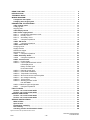
READ THIS FIRST 4. . . . . . . . . . . . . . . . . . . . . . . . . . . . . . . . . . . . . . . . . . . . . . . . . . . . . . . . . . . . . . . . .
INTRODUCTION 4. . . . . . . . . . . . . . . . . . . . . . . . . . . . . . . . . . . . . . . . . . . . . . . . . . . . . . . . . . . . . . . . . . .
TECHNICAL DATA 5. . . . . . . . . . . . . . . . . . . . . . . . . . . . . . . . . . . . . . . . . . . . . . . . . . . . . . . . . . . . . . . . .
WIRING DIAGRAM 6. . . . . . . . . . . . . . . . . . . . . . . . . . . . . . . . . . . . . . . . . . . . . . . . . . . . . . . . . . . . . . . . .
Component description 6. . . . . . . . . . . . . . . . . . . . . . . . . . . . . . . . . . . . . . . . . . . . . . . . . . . . . . . . . .
CaddyTig 200, OrigoTig 200 8. . . . . . . . . . . . . . . . . . . . . . . . . . . . . . . . . . . . . . . . . . . . . . . . . . . . . .
DESCRIPTION OF OPERATION 11. . . . . . . . . . . . . . . . . . . . . . . . . . . . . . . . . . . . . . . . . . . . . . . . . . . . .
1AP1 Control panel 11. . . . . . . . . . . . . . . . . . . . . . . . . . . . . . . . . . . . . . . . . . . . . . . . . . . . . . . . . . . . . .
CaddyTig 200 11. . . . . . . . . . . . . . . . . . . . . . . . . . . . . . . . . . . . . . . . . . . . . . . . . . . . . . . . . . . . . . . . . . . .
OrigoTig 200 12. . . . . . . . . . . . . . . . . . . . . . . . . . . . . . . . . . . . . . . . . . . . . . . . . . . . . . . . . . . . . . . . . . . . .
1AP2 Display board 12. . . . . . . . . . . . . . . . . . . . . . . . . . . . . . . . . . . . . . . . . . . . . . . . . . . . . . . . . . . . .
2AP1 Power supply board 14. . . . . . . . . . . . . . . . . . . . . . . . . . . . . . . . . . . . . . . . . . . . . . . . . . . . . . .
2AP1:1 Interference suppressor circuit 14. . . . . . . . . . . . . . . . . . . . . . . . . . . . . . . . . . . . . . . . . . . .
2AP1:2 Primary circuit 14. . . . . . . . . . . . . . . . . . . . . . . . . . . . . . . . . . . . . . . . . . . . . . . . . . . . . . . . . .
2AP1:3 Secondary circuit 15. . . . . . . . . . . . . . . . . . . . . . . . . . . . . . . . . . . . . . . . . . . . . . . . . . . . . . .
2AP1 Component positions 16. . . . . . . . . . . . . . . . . . . . . . . . . . . . . . . . . . . . . . . . . . . . . . . . . . . .
10AP1 TIG board 18. . . . . . . . . . . . . . . . . . . . . . . . . . . . . . . . . . . . . . . . . . . . . . . . . . . . . . . . . . . . . . . .
10AP1 Component positions 19. . . . . . . . . . . . . . . . . . . . . . . . . . . . . . . . . . . . . . . . . . . . . . . . . . . .
15AP1 Power board 20. . . . . . . . . . . . . . . . . . . . . . . . . . . . . . . . . . . . . . . . . . . . . . . . . . . . . . . . . . . . .
Charging circuit 20. . . . . . . . . . . . . . . . . . . . . . . . . . . . . . . . . . . . . . . . . . . . . . . . . . . . . . . . . . . . . . . . . .
Supply to 2AP1 21. . . . . . . . . . . . . . . . . . . . . . . . . . . . . . . . . . . . . . . . . . . . . . . . . . . . . . . . . . . . . . . . . .
Gate driver stages 21. . . . . . . . . . . . . . . . . . . . . . . . . . . . . . . . . . . . . . . . . . . . . . . . . . . . . . . . . . . . . . . .
Switching circuit 21. . . . . . . . . . . . . . . . . . . . . . . . . . . . . . . . . . . . . . . . . . . . . . . . . . . . . . . . . . . . . . . . . .
15AP1 Component positions 22. . . . . . . . . . . . . . . . . . . . . . . . . . . . . . . . . . . . . . . . . . . . . . . . . . . .
15AP2 Secondary board 23. . . . . . . . . . . . . . . . . . . . . . . . . . . . . . . . . . . . . . . . . . . . . . . . . . . . . . . . .
15AP2 Component positions 23. . . . . . . . . . . . . . . . . . . . . . . . . . . . . . . . . . . . . . . . . . . . . . . . . . . .
20AP1 Control board 24. . . . . . . . . . . . . . . . . . . . . . . . . . . . . . . . . . . . . . . . . . . . . . . . . . . . . . . . . . . .
20AP1:1 Power supply 24. . . . . . . . . . . . . . . . . . . . . . . . . . . . . . . . . . . . . . . . . . . . . . . . . . . . . . . . . . .
20AP1:2 Control panel interface circuits 26. . . . . . . . . . . . . . . . . . . . . . . . . . . . . . . . . . . . . . . . . . . .
LED display driver 27. . . . . . . . . . . . . . . . . . . . . . . . . . . . . . . . . . . . . . . . . . . . . . . . . . . . . .
Rotary encoder input 28. . . . . . . . . . . . . . . . . . . . . . . . . . . . . . . . . . . . . . . . . . . . . . . . . . . .
Push button filters 28. . . . . . . . . . . . . . . . . . . . . . . . . . . . . . . . . . . . . . . . . . . . . . . . . . . . . . .
20AP1:3 Remote control input 29. . . . . . . . . . . . . . . . . . . . . . . . . . . . . . . . . . . . . . . . . . . . . . . . . . . .
20AP1:4 Pulse width modulator 29. . . . . . . . . . . . . . . . . . . . . . . . . . . . . . . . . . . . . . . . . . . . . . . . . . .
20AP1:5 Temperature monitoring 29. . . . . . . . . . . . . . . . . . . . . . . . . . . . . . . . . . . . . . . . . . . . . . . . .
20AP1:6 Shunt and current control amplifier 30. . . . . . . . . . . . . . . . . . . . . . . . . . . . . . . . . . . . . . . .
20AP1:7 Arc voltage monitoring 31. . . . . . . . . . . . . . . . . . . . . . . . . . . . . . . . . . . . . . . . . . . . . . . . . . .
20AP1:8 TIG functions 31. . . . . . . . . . . . . . . . . . . . . . . . . . . . . . . . . . . . . . . . . . . . . . . . . . . . . . . . . . .
20AP1:9 Welding process control 32. . . . . . . . . . . . . . . . . . . . . . . . . . . . . . . . . . . . . . . . . . . . . . . . .
Hot start MMA 32. . . . . . . . . . . . . . . . . . . . . . . . . . . . . . . . . . . . . . . . . . . . . . . . . . . . . . . . . .
20AP1:10 Machine type configuration 33. . . . . . . . . . . . . . . . . . . . . . . . . . . . . . . . . . . . . . . . . . . . . . .
20AP1 Component positions 34. . . . . . . . . . . . . . . . . . . . . . . . . . . . . . . . . . . . . . . . . . . . . . . . . . . .
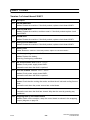
FAULT CODES 36. . . . . . . . . . . . . . . . . . . . . . . . . . . . . . . . . . . . . . . . . . . . . . . . . . . . . . . . . . . . . . . . . . . .
Version 1 of circuit board 20AP1 36. . . . . . . . . . . . . . . . . . . . . . . . . . . . . . . . . . . . . . . . . . . . . . . . .
Version 2 of circuit board 20AP1 37. . . . . . . . . . . . . . . . . . . . . . . . . . . . . . . . . . . . . . . . . . . . . . . . .
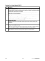
SERVICE FUNCTIONS 38. . . . . . . . . . . . . . . . . . . . . . . . . . . . . . . . . . . . . . . . . . . . . . . . . . . . . . . . . . . . .
Version 1 of circuit board 20AP1 38. . . . . . . . . . . . . . . . . . . . . . . . . . . . . . . . . . . . . . . . . . . . . . . . .
Version 2 of circuit board 20AP1 41. . . . . . . . . . . . . . . . . . . . . . . . . . . . . . . . . . . . . . . . . . . . . . . . .
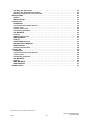
SERVICE INSTRUCTIONS 44. . . . . . . . . . . . . . . . . . . . . . . . . . . . . . . . . . . . . . . . . . . . . . . . . . . . . . . . . .
What is ESD? 44. . . . . . . . . . . . . . . . . . . . . . . . . . . . . . . . . . . . . . . . . . . . . . . . . . . . . . . . . . . . . . . . . . .
Special tools 44. . . . . . . . . . . . . . . . . . . . . . . . . . . . . . . . . . . . . . . . . . . . . . . . . . . . . . . . . . . . . . . . . . . .
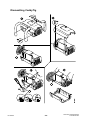
Dismantling CaddyTig 45. . . . . . . . . . . . . . . . . . . . . . . . . . . . . . . . . . . . . . . . . . . . . . . . . . . . . . . . . . .
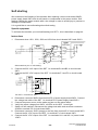
Soft starting 46. . . . . . . . . . . . . . . . . . . . . . . . . . . . . . . . . . . . . . . . . . . . . . . . . . . . . . . . . . . . . . . . . . . .
Checking rectifier and freewheel diodes 48. . . . . . . . . . . . . . . . . . . . . . . . . . . . . . . . . . . . . . . . . .

S0740 800 164/E061205/P62
© ESAB AB 2004
- 3 -TOCe
Rights reserved to alter specifications without notice.
Checking the gate pulses 49. . . . . . . . . . . . . . . . . . . . . . . . . . . . . . . . . . . . . . . . . . . . . . . . . . . . . . . .
Checking the semiconductor module 50. . . . . . . . . . . . . . . . . . . . . . . . . . . . . . . . . . . . . . . . . . . . .
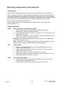
Mounting components on the heat sink 51. . . . . . . . . . . . . . . . . . . . . . . . . . . . . . . . . . . . . . . . . . .
INSTRUCTIONS 52. . . . . . . . . . . . . . . . . . . . . . . . . . . . . . . . . . . . . . . . . . . . . . . . . . . . . . . . . . . . . . . . . . .
SAFETY 52. . . . . . . . . . . . . . . . . . . . . . . . . . . . . . . . . . . . . . . . . . . . . . . . . . . . . . . . . . . . . . . . . . . . . . . .
INSTALLATION 52. . . . . . . . . . . . . . . . . . . . . . . . . . . . . . . . . . . . . . . . . . . . . . . . . . . . . . . . . . . . . . . . .
CaddyTig 200 53. . . . . . . . . . . . . . . . . . . . . . . . . . . . . . . . . . . . . . . . . . . . . . . . . . . . . . . . . . . . . . . . . . . . .
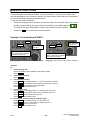
OPERATION 53. . . . . . . . . . . . . . . . . . . . . . . . . . . . . . . . . . . . . . . . . . . . . . . . . . . . . . . . . . . . . . . . . . . .
Connections and control devices 53. . . . . . . . . . . . . . . . . . . . . . . . . . . . . . . . . . . . . . . . . . . . . . . . .
Control panel 53. . . . . . . . . . . . . . . . . . . . . . . . . . . . . . . . . . . . . . . . . . . . . . . . . . . . . . . . . . . . . . . . . . .
Remote control unit 54. . . . . . . . . . . . . . . . . . . . . . . . . . . . . . . . . . . . . . . . . . . . . . . . . . . . . . . . . . . . .
Overheating protection 54. . . . . . . . . . . . . . . . . . . . . . . . . . . . . . . . . . . . . . . . . . . . . . . . . . . . . . . . . .
TIG WELDING 54. . . . . . . . . . . . . . . . . . . . . . . . . . . . . . . . . . . . . . . . . . . . . . . . . . . . . . . . . . . . . . . . . . .
Settings 54. . . . . . . . . . . . . . . . . . . . . . . . . . . . . . . . . . . . . . . . . . . . . . . . . . . . . . . . . . . . . . . . . . . . . . . .
Hidden TIG functions 56. . . . . . . . . . . . . . . . . . . . . . . . . . . . . . . . . . . . . . . . . . . . . . . . . . . . . . . . . . . .
MMA WELDING 57. . . . . . . . . . . . . . . . . . . . . . . . . . . . . . . . . . . . . . . . . . . . . . . . . . . . . . . . . . . . . . . . .
Settings 57. . . . . . . . . . . . . . . . . . . . . . . . . . . . . . . . . . . . . . . . . . . . . . . . . . . . . . . . . . . . . . . . . . . . . . . .
Hidden MMA functions 57. . . . . . . . . . . . . . . . . . . . . . . . . . . . . . . . . . . . . . . . . . . . . . . . . . . . . . . . . .
WELDING DATA MEMORY 58. . . . . . . . . . . . . . . . . . . . . . . . . . . . . . . . . . . . . . . . . . . . . . . . . . . . . . .
MAINTENANCE 58. . . . . . . . . . . . . . . . . . . . . . . . . . . . . . . . . . . . . . . . . . . . . . . . . . . . . . . . . . . . . . . . .
Cleaning the dust filter 58. . . . . . . . . . . . . . . . . . . . . . . . . . . . . . . . . . . . . . . . . . . . . . . . . . . . . . . . . .
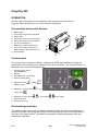
OrigoTig 200 59. . . . . . . . . . . . . . . . . . . . . . . . . . . . . . . . . . . . . . . . . . . . . . . . . . . . . . . . . . . . . . . . . . . . . .
OPERATION 59. . . . . . . . . . . . . . . . . . . . . . . . . . . . . . . . . . . . . . . . . . . . . . . . . . . . . . . . . . . . . . . . . . . .
Connections and control devices 59. . . . . . . . . . . . . . . . . . . . . . . . . . . . . . . . . . . . . . . . . . . . . . . . .
Control panel 59. . . . . . . . . . . . . . . . . . . . . . . . . . . . . . . . . . . . . . . . . . . . . . . . . . . . . . . . . . . . . . . . . . .
Overheating protection 59. . . . . . . . . . . . . . . . . . . . . . . . . . . . . . . . . . . . . . . . . . . . . . . . . . . . . . . . . .
TIG WELDING 60. . . . . . . . . . . . . . . . . . . . . . . . . . . . . . . . . . . . . . . . . . . . . . . . . . . . . . . . . . . . . . . . . . .
Settings 60. . . . . . . . . . . . . . . . . . . . . . . . . . . . . . . . . . . . . . . . . . . . . . . . . . . . . . . . . . . . . . . . . . . . . . . .
MMA WELDING 61. . . . . . . . . . . . . . . . . . . . . . . . . . . . . . . . . . . . . . . . . . . . . . . . . . . . . . . . . . . . . . . . .
MAINTENANCE 61. . . . . . . . . . . . . . . . . . . . . . . . . . . . . . . . . . . . . . . . . . . . . . . . . . . . . . . . . . . . . . . . .
SPARE PARTS 61. . . . . . . . . . . . . . . . . . . . . . . . . . . . . . . . . . . . . . . . . . . . . . . . . . . . . . . . . . . . . . . . . . . .

S0740 800 164/E061205/P62
© ESAB AB 2004
- 4 -
ct27bd1
READ THIS FIRST
Maintenance and repair work should be performed by an experienced person, and
electrical work only by a trained electrician. Use only recommended replacement parts.
This service manual is intended for use by technicians with electrical/electronic training for
help in connection with fault-tracing and repair.
Use the wiring diagram as a form of index for the description of operation. The circuit
board is divided into numbered blocks, which are described individually in more detail in
the description of operation. All component names in the wiring diagram are listed in the
component description.
This manual contains details of all design changes that have been made up to and
including November 2006.
The manual is valid for:
CaddyTig 200 and OrigoTig 200 with serial no. 402-xxx-xxxx, 610-xxx-xxxx, 613-xxx-xxxx.
Caddyt Tig 200i and Origot Tig 200i with serial no. 620-xxx-xxxx.
The CaddyTig 200, OrigoTig 200, Caddyt Tig 200i and Origot Tig 200i are designed
and tested in accordance with international and European standards IEC/EN 60974.
On completion of service or repair work, it is the responsibility of the person(s)
performing the work to ensure that the product still complies with the requirements of
the above standard.
INTRODUCTION
The Power sources are renamed:
New name Old name
Caddyt Tig 200i CaddyTig 200
Origot Tig 200i OrigoTig 200
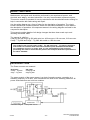
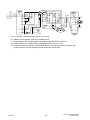
The power module of the power source is a single forward converter, operating at a
switching frequency of 65 kHz. IGBT transistors are used as the switching elements. All
power semiconductors are built into modules.
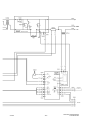
Schematic diagram of the power source

S0740 800 164/E061205/P62
© ESAB AB 2004
- 5 -
ct27bd1
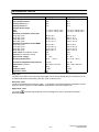
TECHNICAL DATA
CaddyTig 200 OrigoTig 200
Mains voltage 230 V $10% 1∼ 50/60 Hz 230 V $10% 1∼ 50/60 Hz
Fuse (delayed-action) 16 A 16 A
Primary current I
max
36 A 36 A
Primary current I
eff
21 A 21 A
Voltage/current range
(TIG)
(MMA)
3 A / 10 V -200 A / 18 V
4 A / 20 V -150 A / 26 V
3 A / 10 V -200 A / 18 V
4 A / 20 V -150 A / 26 V
Maximum permissible load at TIG
25% duty cycle
35% duty cycle
60% duty cycle
100% duty cycle
200 A / 18 V
180 A / 17 V
140 A / 15.5 V
110 A / 14.5 V
200 A / 18 V
180 A / 17 V
140 A / 15.5 V
110 A / 14.5 V
Maximum permissible load at MMA
25% duty cycle
35% duty cycle
60% duty cycle
100% duty cycle
150 A / 26 V
140 A / 25.5 V
110 A / 24.5 V
90 A / 23.5 V
150 A / 26 V
140 A / 25.5 V
110 A / 24.5 V
90 A / 23.5 V
Power factor at maximum current 0.62 0.62
Efficiency at maximum current 79 % 79 %
Open-circuit voltage 71 - 78 V 71 - 78 V
Operating temperature -10° C - + 40° C -10 ° C till + 40° C
Constant A-weighed sound pressure <70 db <70 db
Dimensions, l x b x h 394 x 267 x 274 mm 380 x 180 x 300 mm
Weight 10 kg 9 kg
Enclosure class IP 23C IP 23C
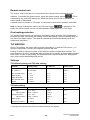
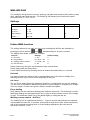
Application class
Duty cycle
The duty cycle refers to the time as a percentage of a ten-minute period that you can weld or cut at
a certain load without overloading. The duty cycle is valid for 40° C.
Enclosure class
The IP code indicates the enclosure class, i. e. the degree of protection against penetration by solid
objects or water. Equipment marked IP23 is designed for indoor and outdoor use.
Application class
The symbol indicates that the power source is designed for use in areas with increased
electrical hazard.

S0740 800 164/E061205/P62
© ESAB AB 2004
- 6 -
ct27bd1
WIRING DIAGRAM
The power source is based on a number of function modules. These are described in the
component descriptions on the following pages. Wire numbers and component names in
the wiring diagram show to which module each component belongs.
Wires/cables within modules are marked 100 - 6999.
Circuit boards within each module have names such as 20AP1 - 20AP99.
15 = module association, 1-69
AP = circuit board
1 = individual identification number, 0-99
Components within modules are named in a similar way.
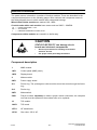
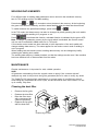
CAUTION
STATIC ELECTRICITY can damage circuit
boards and electronic components.
S Observe precautions for handling electrostatic-
sensitive devices.
S Use proper static-proof bags and boxes.
ESD
Component description
1 MMC module.
1AP1 Control panel (MMC panel).
1AP2 Display board.
2 Mains module.
2AP1 Power supply board.
2L1 Ferrite ring. The yellow/green cable must be wound two turns through the ferrite
ring.
2L2 Ferrite ring.
2QF1 Mains switch.
2XS1 Flat pin sockets. Important: to obtain a proper electric connection, the complete
cord set must be replaced if the sockets have to be replaced.
10 TIG module.
10AP1 TIG board.
10TV1 HF transformer.
10YV1 Gas valve, 230 V AC.

S0740 800 164/E061205/P62
© ESAB AB 2004
- 7 -
ct27bd1
15 Power module.
15AP1 Power board.
15AP2 Secondary board.
15C1 Smoothing capacitor, 2000 uF.
15D1 Diode module with rectifier and freewheel diodes.
15EV1 Fan.
15L1 Inductor.
15RS1 Shunt. 60 mV at 100 A.
15ST1 Thermal switch, fitted in the winding of main transformer 15TM1. See page 29.
15ST2 Thermal switch, fitted on the heat sink. See page 29.
15TM1 Main transformer.
20AP1 Controller circuit board.
29XS5 Remote control socket. Only CaddyTig 200.

S0740 800 164/E061205/P62
© ESAB AB 2004
- 8 -
ct27bd1
CaddyTig 200, OrigoTig 200

S0740 800 164/E061205/P62
© ESAB AB 2004
- 9 -
ct27bd1

S0740 800 164/E061205/P62
© ESAB AB 2004
- 10 -
ct27bd1

S0740 800 164/E061205/P62
© ESAB AB 2004
- 11 -
ct27bd1
DESCRIPTION OF OPERATION
This description of operation describes the function of circuit boards and other components
in the power source. It is divided into sections, numbered to correspond to the circuit board
numbers and divisions into function blocks.
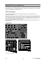
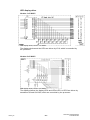
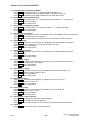
1AP1 Control panel
The control board processes the control signals to/from the control panel. See the
description on page 26.
When the machine is switched on, the LEDs of the control panel and the display segments
are tested by the software. The display then shows the machine type and software version.
Some of the LEDs of the control panel may gleam very weak when they are off, this is no
fault. An activated LED lights with a clear light.
The control panel LEDs and the display segments can be tested by service functions, see
pages 38 to 43.
CaddyTig 200
A
B
C
D
E
H
G
K
J
L
A1
A2
A3
A5
A6
B1
A7
B2
B5
C1
C2
C3 C5
C6
C7
C4
D4 D5D3
D1
D2
B6 B7
F
X1
C1
C2
C3
C4
C5
C7
C6
B1
B2
B7
A1
A2
A3
A5
A7
A6
D1
D5
B6
B5
D4
D3
D2
4
3
2
1
11
10
9
8
7
5
6
Green LEDs, except D2 (yellow)
X1
GREEN LED
L
24
KJHGFEDCBA
22
21
20
19
18
17
16
15
14
13
12
23
Buttons
Control panel, CaddyTig 200

S0740 800 164/E061205/P62
© ESAB AB 2004
- 12 -
ct27bd1
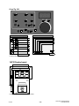
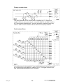
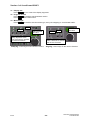
OrigoTig 200
A
C
D
E
A1
A2
A6 B1
B3
A7
B2
B4
B5
F
X1
2
1
11
10
9
8
7
5
6
B1
B2
B3
B4
A1
A2
A7
A6
B5
Green LEDs, except B5 (yellow)
X1
GREEN LED
24
FEDCBA
23
17
16
15
14
13
12
Buttons
Control panel, OrigoTig 200
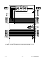
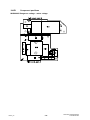
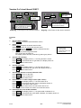
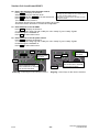
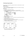
1AP2 Display board
Component positions of the display board

S0740 800 164/E061205/P62
© ESAB AB 2004
- 13 -
ct27bd1
Circuit diagram of the display board
The display segments can be tested by a service function, see pages 38 to 43.

S0740 800 164/E061205/P62
© ESAB AB 2004
- 14 -
ct27bd_2
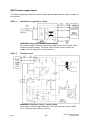
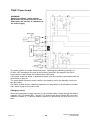
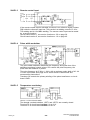
2AP1 Power supply board
The power supply board filters the mains voltage and generates internal supply voltages for
the machine.
2AP1:1 Interference suppressor circuit
WARNING! Dangerous voltage - mains voltage.
The mains voltage is filtered by the power supply board. Power board 15AP1
rectifies the mains voltage. TIG board 10AP1 uses the mains voltage for
supply to the HF generator and the gas valve.
2AP1:2 Primary circuit
WARNING! Dangerous voltage - mains voltage.
The primary circuit is supplied with 325 V DC from the power board, 15AP1.
S1 is a fuse with high rupturing capacity.

S0740 800 164/E061205/P62
© ESAB AB 2004
- 15 -
ct27bd_2
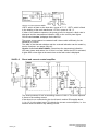
Transistor Q5 is the switching element in a switched voltage supply. The
secondary voltage, +24 V, is sensed by IC2 and controlled by IC1.
The isolation voltage of transformer T1 and optocoupler IC3 is 4 kV.
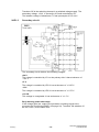
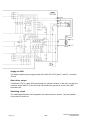
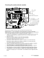
2AP1:3 Secondary circuit
The secondary circuit delivers the following voltages:
+24 V
The voltage is controlled by IC1 on the primary side. It has a tolerance of
$0.6 V.
+5 V
The voltage is controlled by VR3. It has a tolerance of $0.25 V.
-15 V
The voltage is controlled by VR2. It has a tolerance of $0.75 V.
+13 VB
This voltage is unregulated. It has a tolerance of $1.5 V.
Early warning power shut down
If the voltage goes low, output PS4 generates a warning signal to the
processor on circuit board 20AP1 (see page 24). Transistor Q6 switches off
the fan, 15EV1, at the same time.

S0740 800 164/E061205/P62
© ESAB AB 2004
- 16 -
ct27bd_2
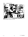
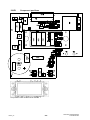
2AP1 Component positions
WARNING! Dangerous voltage - mains voltage.

S0740 800 164/E061205/P62
© ESAB AB 2004
- 17 -
page

S0740 800 164/E061205/P62
© ESAB AB 2004
- 18 -
ct27bd_10
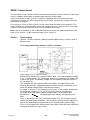
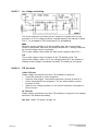
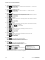
10AP1 TIG board
WARNING! Dangerous voltage - mains voltage.
The relay contacts, the gas valve 10YV1, the HF generator TR2 and the primary side of
transformer TR1 are connected to 230 V mains voltage.
Circuit diagram of the TIG functions of the CaddyTig and OrigoTig
The processor on circuit board 20AP1 controls the HF generator and gas valve. They can
be tested by service functions, see pages 38 to 43.
HF generator
When the welding torch switch is operated, and the open-circuit voltage is over 50 V, relay
RE2 closes and turns on the HF generator, TR2. It remains activated until the arc strikes, or
for a maximum of 0.7 seconds.
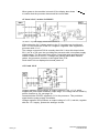
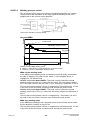
The voltage on the primary side of HF transformer 10TV1 is about 550 V. The secondary
voltage is about 11 kV if a 4 metre long welding torch is connected. If the welding torch is
16 metre long, the HF spark is about 8 kV.
Due to electromagnetic interference regulations, the energy in the HF ignition spark is
limited, and so the HF spark weakens with increasing length of the torch. The HF ignition is
satisfactory for welding torches up to 16 metres.
Gas valve
When the torch switch is operated, relay RE1 closes and energizes the gas valve.
When the torch switch is released and the gas post-flow time has elapsed, the gas valve is
deactivated.
TIG torch switch
The secondary windings of transformer TR1 and rectifier bridge D3-D6 produce 24 V DC.
This voltage energizes relay RE3 when the torch switch is closed.
The torch switch can be tested by a service function, see pages 38 to 43.

S0740 800 164/E061205/P62
© ESAB AB 2004
- 19 -
ct27bd_10
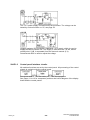
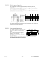
10AP1 Component positions
WARNING! Dangerous voltage - mains voltage.

S0740 800 164/E061205/P62
© ESAB AB 2004
- 20 -
ct27bd_15
WARNING!
Dangerous voltage - mains voltage.
Never make any measurements on this
board when the machine is connected to
the mains supply.
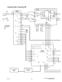
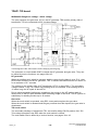
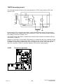
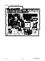
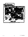
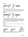
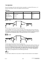
15AP1 Power board
The power module is a single forward converter, operating at a switching frequency of
65 kHz. IGBT transistors are used as the switching elements. See page 49 and 50 for
screen traces of waveforms and measurement instructions.
If the power board has failed, a replacement board must be mounted in accordance with the
instructions on page 51.
The power board carries the mains rectifier, the charging circuit, the switching circuit and
the gate circuit.
The mains rectifier and the switching transistors are integrated in a semiconductor module,
PM1, which is part of the power board.
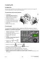
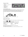
Charging circuit
When the mains power supply is turned on, the rectified mains voltage charges smoothing
capacitor 15C1 via resistor R31. Thyristor TY1 short-circuits charge resistor R31 when the
machine is loaded. If TY1 did not conduct, resistor R31 would burn out when the unit is on
load.
Page is loading ...
Page is loading ...
Page is loading ...
Page is loading ...
Page is loading ...
Page is loading ...
Page is loading ...
Page is loading ...
Page is loading ...
Page is loading ...
Page is loading ...
Page is loading ...
Page is loading ...
Page is loading ...
Page is loading ...
Page is loading ...
Page is loading ...
Page is loading ...
Page is loading ...
Page is loading ...
Page is loading ...
Page is loading ...
Page is loading ...
Page is loading ...
Page is loading ...
Page is loading ...
Page is loading ...
Page is loading ...
Page is loading ...
Page is loading ...
Page is loading ...
Page is loading ...
Page is loading ...
Page is loading ...
Page is loading ...
Page is loading ...
Page is loading ...
Page is loading ...
Page is loading ...
Page is loading ...
Page is loading ...
Page is loading ...
-
 1
1
-
 2
2
-
 3
3
-
 4
4
-
 5
5
-
 6
6
-
 7
7
-
 8
8
-
 9
9
-
 10
10
-
 11
11
-
 12
12
-
 13
13
-
 14
14
-
 15
15
-
 16
16
-
 17
17
-
 18
18
-
 19
19
-
 20
20
-
 21
21
-
 22
22
-
 23
23
-
 24
24
-
 25
25
-
 26
26
-
 27
27
-
 28
28
-
 29
29
-
 30
30
-
 31
31
-
 32
32
-
 33
33
-
 34
34
-
 35
35
-
 36
36
-
 37
37
-
 38
38
-
 39
39
-
 40
40
-
 41
41
-
 42
42
-
 43
43
-
 44
44
-
 45
45
-
 46
46
-
 47
47
-
 48
48
-
 49
49
-
 50
50
-
 51
51
-
 52
52
-
 53
53
-
 54
54
-
 55
55
-
 56
56
-
 57
57
-
 58
58
-
 59
59
-
 60
60
-
 61
61
-
 62
62


ESAB Origo™ Tig 200i User manual
- Category
- Welding System
- Type
- User manual
- This manual is also suitable for
Ask a question and I''ll find the answer in the document
Finding information in a document is now easier with AI
Related papers
-
ESAB CaddyTig 150 User manual
-
-
-
ESAB Origo™Tig 150 User manual
-
ESAB Origo™Tig 150, Origo™Tig 200 User manual
-
-
ESAB CaddyTig HF User manual
-
ESAB Caddy Arc 150i User manual
-
ESAB TA24 Origo™ User manual
-
Other documents
-
Cebora 276 Bi-Welder TIG 1600 DC HF User manual
-
 Arcoweld ArcoTig HF200P User manual
-
-
-
Roland M-200i Installation guide
-
 AES Masterweld 204T User manual
-
WIA Weldarc 200i AC/DC Owner's manual
-
Hyundai MMA series User manual
-
Evolveo Explorer Owner's manual
-

