ESAB Welding Control Unit PEI User manual
- Category
- Welding System
- Type
- User manual

Valid for serial no. 2430740 801 108 2011-02-14
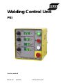
Welding Control Unit
PEI
104
Service manual

-- 2 --
Rights reserved to alter specifications without notice.
ENGLISH 3..............................................

ENGLISH
-- 3 --
TOCe
1 READ THIS FIRST 4..................................................
1.1 General 4..................................................................
1SAFETY 5...........................................................
2 COMPONENT DESCRIPTION 8.......................................
3 Circuit diagrams 9...................................................
3.1 Welding Control Unit PEI 9...................................................
3.2 Control PC board A1 10......................................................
3.3 Motor drive PC boards (A2, A3) 13.............................................
4 TECHNICAL DESCRIPTION 14.........................................
4.1 Controls on the front panel 14..................................................
4.2 Controls on the rear panel 15..................................................
4.3 View from inside the Rear panel 16.............................................
4.4 Transformer T1 18...........................................................
4.5 Rectifier V1 18...............................................................
4.6 Control PC board A1 19......................................................
4.7 Motor drive PC boards (A2 - feed control, A3 - tractor control) 21...................
5 INSTALLATION 23....................................................
5.1 General 23..................................................................
5.2 LAF welding power sources - analogue mode 28.................................
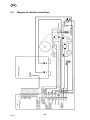
5.3 Diagram of external connections 29.............................................
SPARE PARTS LIST 30..................................................

-4-
fzb3d1ea
1READTHISFIRST
1.1 General
This service manual is intended for use by technicians with electrical/electronic
training, for help in connection with fault-tracing and/or repair.
This manual contains details of all design changes that have been made up to and
including February 2003.
For further information see the Welding control unit ( PEI) instruction
manual 0449 331 xxx.
GB

-5-
SafeArcS GB
1SAFETY
Users of ESAB welding equipment have the ultimate responsibility for ensuring that
anyone who works on or near the equipment observes all the relevant safety pre-
cautions. Safety precautions must meet the requirements that apply to this type of
welding equipment. The following recommendations should be observed in addition
to the standard regulations that apply to the workplace.
All work m ust be carried out by trained personnel well-acquainted with the oper-
ation of the welding equipment.
Incorrect operation of the equipment may lead to hazardous situations which can
result in injury to the operator and damage to the equipment.
1. Anyone who uses the welding equipment must be familiar with:
S its operation
S location of emergency stops
S its function
S relevant safety precautions
S welding
2. The operator must ensure that:
S no unauthorised person is stationed within the working area of the
equipment when it is started up.
S no-one is unprotected when the arc is struck
3. The workplace must:
S be suitable for the purpose
S be free from draughts
4. Personal safety equipment
S Always wear recommended personal safety equipment, such as safety
glasses, flame-proof clothing, safety gloves. Note! Do not use safety
gloves when replacing wire.
S Do not wear loose-fitting items, such as scarves, bracelets, rings, etc.,
which could become trapped or cause burns.
5. Protection against other risks
S Dust particles of a cer tain size can be harmful to man. A ventilation system
and extractor should therefore be provided to eliminate this risk.
6. General precautions
S Make sure the r eturn cable is connected securely.
S Work on high voltage equipment may only be carried out by a qualified
electrician.
S Appropriate fire extinquishing equipment must be clearly marked and close
at hand.
S Lubrication and maintenance must not be carried out on the equipment
during operation.
GB

-6-
SafeArcS GB
WARNING, RISK OF CRUSHING!
Do not use safety gloves when replacing wire, feed rollers and wire bobbins.
GB

WARNING
ARC WELDING AND CUTTING CAN BE INJURIOUS TO YOURSELF AND
OTHERS. TAKE PRECAUTIONS WHEN WELDING. ASK FOR YOUR
EMPLOYER'S SAFETY PRACTICES WHICH SHOULD BE BASED ON MANU-
FACTURER'S HAZARD DATA.
ELECTRIC SHOCK - Can kill
S Install and earth the welding unit in accordance with applicable standards.
S Do not touch live electrical parts or electrodes with bare skin, wet gloves or wet
clothing.
S Insulate yourself from earth and the workpiece.
S Ensure your working stance is safe.
FUMES AND GASES - Can be dangerous to health
S Keep your head out of the fumes.
S Use ventilation, extraction at the arc, or both, to keep fumes and gases from
your breathing zone and the general area.
ARC RAYS - Can injure eyes and burn skin
S Protect your eyes and body. Use the correct welding screen and filter lens and
wear protective clothing.
S Protect bystanders with suitable screens or curtains.
FIRE HAZARD
S Sparks (spatter) can cause fire. Make sure therefore that there are no inflam-
mable m aterials nearby.
NOISE - Excessive n o ise can da mage hearing
S Protect your ears. Use ear defenders or other hearing protection.
S Warn bystanders of the risk.
MALFUNCTION
S Call for expert assistance in the event of malfunction.
PROTECT YOURSELF AND OTHERS!
READ AND UNDERSTAND THE INSTRUCTION MAN-
UAL BEFORE INSTALLING OR OPERATING.
-7-
SafeArcS GB
GB

-8-
fzb3d2ea
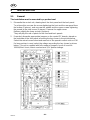
2 COMPONENT DESCRIPTION
The component description refers to the component names in the connection
diagram.
A1 Control PC board, see on page 10.
A2, A3 Motor drive PC boards, see on page 13.
A4 PC board with potentiometer
C1, C2, C3 EMI capacitors
H1/ S1 ON lamp
R1 Voltage adjustment (potentiometer)
R2 Wire speed adjustment (potentiometer)
R3 Travel speed adjustment (potentiometer)
S1 Start (welding) - pushbutton
S2 Stop (welding & travel) - pushbutton
S3 Start (travel) - pushbutton
S4 Emergency switch - pushbutton
S5 Inching, up & down - toggle switch
S6 Direction of travel - toggle switch
T1 Auxiliary transformer, see on page 18.
V1 Rectifier, see on page 18.
X1 Socket (for PS cable connection), see on page 16.
X2 Screw terminal (for external connections), see on page 17.
GB

-9-
fzb3d2ea
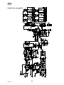
3 Circuit diagrams
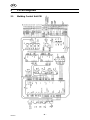
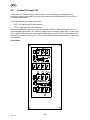
3.1 Welding Control Unit PEI
GB

-10-
fzb3d2ea
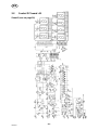
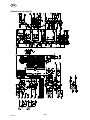
3.2 Control PC board A1
Sheet 1 ( see on p ag e 19)
GB

-11-
fzb3d2ea
Sheet 2 ( see on p ag e 19)
GB

-12-
fzb3d2ea
Sheet 3 ( see on p ag e 19)
GB

-13-
fzb3d2ea
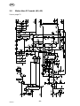
3.3 Motor drive PC boards (A2, A3)
See on page 21
GB

-14-
fzb3d2ea
4 TECHNICAL DESCRIPTION
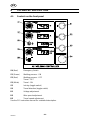
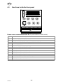
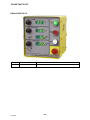
4.1 Controls on the front panel
S4 (Red) Emergency Switch
S1 (Green) Welding process - ON
S2 (Red) Welding process - OFF
Travel - OFF
S3 (White) Travel - ON
S5 Inching (toggle switch)
S6 Travel direction ( toggle switch)
R1 Voltage adjustment
R2 Wire speed adjustment
R3 Travel speed adjustment
See the PEI instruction manual for a detailed description.
GB

-15-
fzb3d2ea
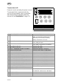
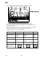
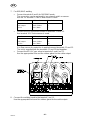
4.2 Controls on the rear panel
DIRECT
START
SCRATCH
START
BURN BACK
1,6
0
0,4
0,8
1,2
6
EXT.
2,0s
Mode setting (1)
Intended for setting DIRECT START or SCRATCH START modes.
S DIRECT START
The feeder motor starts at minimal speed. The tractor is stopped. At the
moment of sensing the welding current, both motors start to operate with
pre-adjusted speeds.
S SCRATCH START
Both the feeder motor and the tractor start at minimal speed. At the moment of
sensing the welding current both motors start to operate with pre-adjusted
speeds.
S EXT.
Extension, which is not currently supported.
Burn-Back time ad ju stment (2)
Intended for setting the burn-back time (maximum 2 seconds).
Adjustment is not active during welding. Setting is refreshed once per second.
GB

-16-
fzb3d2ea
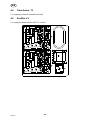
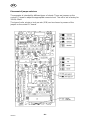
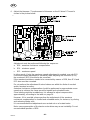
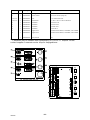
4.3 View from inside the Rear panel
Power source connectio n so cket X1 (23 pole BURNDY male socket)
B,C,D POWER SUPPLY 42V AC (1)
E,F, G POWER SUPPLY 42V AC (1)
J (-) MINUS OF THE POWER SOURCE
K POWER SOURCE START - OPEN COLLECTOR OUTPUT
L COMMON FOR PS START & REFERENCE
M 0...10V REFERENCE
N (-) MINUS OF THE CURRENT SHUNT
P (+) PLUS OF THE CURRENT SHUNT
R EMERGENCY STOP 41 (NC TO 42)
U EMERGENCY STOP 44 (NC TO 43)
V EMERGENCY STOP 43 (NC TO 44)
W (+) PLUS OF THE POWER SOURCE
X ARC VOLTAGE FROM THE WELDING HEAD
Y EMERGENCY STOP 42 (NC TO 41)
GB

-17-
fzb3d2ea
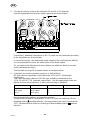
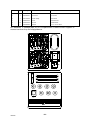
Terminal block X2
External circuits excluding the power source.
The terminal block is placed inside the
unit ( on the rear panel), and is accessible
after dismantling and drawing back the
rear panel (see In stallatio n on page 23).
1 ARC VOLTAGE FROM THE WELDING HEAD connect to welding head
2 MASS POTENTIAL can be connected to the mass via a separate
cable, or connected to terminal 3 or 4,
depending on the polarity of welding.
Initially connected to X2.4 (-PS)
3 (+) POWER SOURCE PLUS alternative for connection of the welding mass
point, initially left open
4 (-) POWER SOURCE MINUS alternative for connection of the welding mass
point, initially connected to X2.2 (MASS)
5 GAS VALVE 42V AC1 connect to gas valve
6 GAS VALVE 42V AC2 connect to gas valve
7 0V DC - COMMON FOR INPUT SIGNALS repeated on terminals 7,10,13,16,
8 FLUX/GAS SELECTION connect to X2.9 (24VDC) for MIG/MAG
9 24V DC - SUPPLY FOR THE INPUT SIGNALS repeated on terminals 9,12,15,18
10 0V DC - COMMON FOR INPUT SIGNALS repeated on terminals 7,10,13,16,
11 WATER FLOW SENSOR (NO) pnp NO output or NO switch
12 24V DC - SUPPLY FOR THE INPUT SIGNALS repeated on terminals 9,12,15,18
13 0V DC - COMMON FOR INPUT SIGNALS repeated on terminals 7,10,13,16,
14 PROXIMTY SENSOR LEFT pnp NO output or NO switch
15 24V DC - SUPPLY FOR THE INPUT SIGNALS repeated on terminals 9,12,15,18
16 0V DC - COMMON FOR INPUT SIGNALS repeated on terminals 7,10,13,16,
17 PROXIMTY SENSOR RIGHT pnp NO output or NO switch
18 24V DC - SUPPLY FOR THE INPUT SIGNALS repeated on terminals 9,12,15,18
19 0V - LASER LAMP SUPPLY connect LED laser pointer
20 3,3V/5V - LASER LAMP SUPPLY
21 FEEDER MOTOR + KSV5035/375 without tacho - SAW
KSV5035/374 without tacho - MIG/MAG
22 FEEDER MOTOR -
23 TRACTOR MOTOR + KSV5035/603 without tacho
24 TRACTOR MOTOR -
GB

-18-
fzb3d2ea
4.4 Transformer T1
For supplying internal separated circuits.
4.5 Rectifier V1
For supplying motor drives with DC current.
GB

-19-
fzb3d2ea
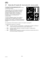
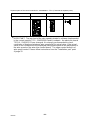
4.6 Control PC board A1
The control PC board performs all functions of controlling the welding process,
including logical, sequential functions and measuring and displaying values of the
essential parameters.
Two trimmers are placed on the board.
S R28 - for adjusting the voltammeter,
S R32 for adjusting the 10V reference.
Both potentiometers are factory set and should not be re-adjusted by the user. For
non-standard applications an auxiliary power source control output X12 can be used.
It is a galvanically separated triac-type output with capacity 42V,1A of permanent AC
load and the peak current up to 16A. It is intended for direct switching-on of the main
PS contactor.
Front view
GB

-20-
fzb3d2ea
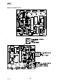
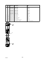
Placement of jumper selectors
The ammeter is intended for different types of shunts. There are jumpers on the
control PC-board to adjust the appropriate current shunt. T he unit is set in factory for
1000A, 60mV.
The type of units, m /min or inch-per-min (IPM) can be chosen by means of the
jumper on the control PC board.
GB
Page is loading ...
Page is loading ...
Page is loading ...
Page is loading ...
Page is loading ...
Page is loading ...
Page is loading ...
Page is loading ...
Page is loading ...
Page is loading ...
Page is loading ...
Page is loading ...
Page is loading ...
Page is loading ...
Page is loading ...
-
 1
1
-
 2
2
-
 3
3
-
 4
4
-
 5
5
-
 6
6
-
 7
7
-
 8
8
-
 9
9
-
 10
10
-
 11
11
-
 12
12
-
 13
13
-
 14
14
-
 15
15
-
 16
16
-
 17
17
-
 18
18
-
 19
19
-
 20
20
-
 21
21
-
 22
22
-
 23
23
-
 24
24
-
 25
25
-
 26
26
-
 27
27
-
 28
28
-
 29
29
-
 30
30
-
 31
31
-
 32
32
-
 33
33
-
 34
34
-
 35
35


ESAB Welding Control Unit PEI User manual
- Category
- Welding System
- Type
- User manual
Ask a question and I''ll find the answer in the document
Finding information in a document is now easier with AI
Related papers
-
ESAB LAF 631 User manual
-
ESAB Parallel connection of LAF-welding power source User manual
-
ESAB FAB User manual
-
-
-
-
-
-
-

