Dometic Blizzard NXT Roof Top Unit Used Installation guide
- Category
- Thermostats
- Type
- Installation guide
This manual is also suitable for
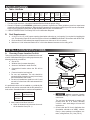
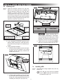
Dometic Blizzard NXT Roof Top Unit Used is a powerful air conditioning system designed to provide reliable cooling for recreational vehicles. With a nominal cooling capacity of 13,500 BTU/hr or 15,000 BTU/hr, it efficiently maintains a comfortable temperature inside your RV. The unit operates on 120 Vac, 60 Hz, 1-phase power and requires a minimum wire size of 12 AWG copper. It comes with an electronic control kit, thermostat, and optional indoor temperature sensor for precise temperature management.
Dometic Blizzard NXT Roof Top Unit Used is a powerful air conditioning system designed to provide reliable cooling for recreational vehicles. With a nominal cooling capacity of 13,500 BTU/hr or 15,000 BTU/hr, it efficiently maintains a comfortable temperature inside your RV. The unit operates on 120 Vac, 60 Hz, 1-phase power and requires a minimum wire size of 12 AWG copper. It comes with an electronic control kit, thermostat, and optional indoor temperature sensor for precise temperature management.


-
 1
1
-
 2
2
-
 3
3
-
 4
4
-
 5
5
-
 6
6
-
 7
7
-
 8
8
-
 9
9
-
 10
10
-
 11
11
-
 12
12
-
 13
13
-
 14
14
-
 15
15
-
 16
16
-
 17
17


Dometic Blizzard NXT Roof Top Unit Used Installation guide
- Category
- Thermostats
- Type
- Installation guide
- This manual is also suitable for
Dometic Blizzard NXT Roof Top Unit Used is a powerful air conditioning system designed to provide reliable cooling for recreational vehicles. With a nominal cooling capacity of 13,500 BTU/hr or 15,000 BTU/hr, it efficiently maintains a comfortable temperature inside your RV. The unit operates on 120 Vac, 60 Hz, 1-phase power and requires a minimum wire size of 12 AWG copper. It comes with an electronic control kit, thermostat, and optional indoor temperature sensor for precise temperature management.
Ask a question and I''ll find the answer in the document
Finding information in a document is now easier with AI
Related papers
-
Dometic Roof top AC Unit 457 and 459_Use Installation guide
-
-
-
-
-
-
Dometic Roof Top Unit Used Installation guide
-
-
-
Other documents
-
Voyager Advent Air Owner's manual
-
-
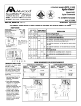 Atwood Mobile Products 1H2C User manual
-
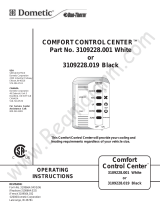 Duo-Therm 3109228.001 Operating Instructions Manual
-
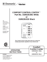 Duo-Therm 3109228.001 Operating Instructions Manual
-
-
Duo-Therm 600315.326 Installation guide
-
Advent AC135HP Operating instructions
-
Furrion FACR15SA-PS User manual
-


