Page is loading ...

16 | SBP 1000-1500 E | E SOL | E cool www.stiebel-eltron.com
CONTENTS | OPERATION
General information
OPERATION
1. General information ��������������������������������������� 16
1.1 Safety instructions ����������������������������������������������16
1.2 Other symbols in this documentation ���������������������� 17
1.3 Units of measurement ����������������������������������������� 17
2. Safety �������������������������������������������������������� 17
2.1 Intended use ����������������������������������������������������� 17
2.2 General safety instructions ����������������������������������� 17
3. Appliance description ������������������������������������� 17
4. Cleaning, care and maintenance ������������������������� 17
5. Troubleshooting �������������������������������������������� 17
INSTALLATION
6. Safety �������������������������������������������������������� 18
6.1 General safety instructions �����������������������������������18
6.2 Regulations, standards and instructions ������������������� 18
7. Appliance description ������������������������������������� 18
7.1 Standard delivery ����������������������������������������������� 18
7.2 Accessories ������������������������������������������������������� 18
8. Preparations ������������������������������������������������ 18
8.1 Installation site �������������������������������������������������� 18
8.2 Transport ���������������������������������������������������������18
9. Preparing for installation ��������������������������������� 19
9.1 Fitting the thermal insulation, if appropriate ������������� 19
9.2 Installing the manual air vent valve�������������������������20
9.3 Fitting the temperature sensor ������������������������������20
9.4 Where appropriate, fit the flanged or threaded
immersion heater. ���������������������������������������������� 20
10. Commissioning ��������������������������������������������� 20
10.1 Commissioning �������������������������������������������������� 21
10.2 Recommissioning ����������������������������������������������� 21
11. Shutting down ���������������������������������������������� 21
12. Maintenance ������������������������������������������������ 21
12.1 Draining the appliance ���������������������������������������� 21
13. Specification ������������������������������������������������ 22
13.1 Dimensions and connections ��������������������������������� 22
13.2 Fault conditions ������������������������������������������������� 26
13.3 Data table ��������������������������������������������������������27
GUARANTEE
ENVIRONMENT AND RECYCLING
OPERATION
1. General information
The chapter “Operation” is intended for appliance users and heat-
ing contractors.
The chapter “Installation” is intended for heating contractors.
Note
Read these instructions carefully before using the appli-
ance and retain them for future reference.
Pass on the instructions to a new user if required.
1.1 Safety instructions
1.1.1 Structure of safety instructions
!
KEYWORD Type of risk
Here, possible consequences are listed that may result
from failure to observe the safety instructions.
Steps to prevent the risk are listed.
1.1.2 Symbols, type of risk
Symbol Type of risk
Injury
Burns
(burns, scalding)
1.1.3 Keywords
KEYWORD Meaning
DANGER Failure to observe this information will result in serious
injury or death.
WARNING Failure to observe this information may result in serious
injury or death.
CAUTION Failure to observe this information may result in non-
serious or minor injury.
!

OPERATION
Safety
www.stiebel-eltron.com SBP 1000-1500 E | E SOL | E cool | 17
ENGLISH
1.2 Other symbols in this documentation
Note
General information is identified by the symbol shown
on the left.
Read these texts carefully.
Symbol Meaning
Material losses
(appliance, consequential, environment)
Appliance disposal
This symbol indicates that you have to do something. The ac-
tion you need to take is described step by step.
1.3 Units of measurement
Note
All measurements are given in mm unless stated oth-
erwise.
2. Safety
2.1 Intended use
This appliance is generally intended to be used for the storage,
heating and cooling of process water.
SBP E cool appliances are also permitted to store cooled process
water down to + 7 °C.
Any other or additional use is inappropriate, in particular usage
with alternative storage media. Observation of these instructions
and of instructions for any accessories used is also part of the
correct use of this appliance.
2.2 General safety instructions
WARNING Burns
There is a risk of scalding at outlet temperatures in ex-
cess of 43 °C.
!
WARNING Injury
The appliance may be used by children aged 8 and up
and persons with reduced physical, sensory or mental
capabilities or a lack of experience provided that they
are supervised or they have been instructed on how to
use the appliance safely and have understood the result-
ing risks. Children must never play with the appliance.
Children must never clean the appliance or perform user
maintenance unless they are supervised.
3. Appliance description
This appliance is designed to extend the operating time of the
heat source and to bridge power-OFF periods. It is also designed
for the hydraulic separation of the volume flow between the
heat/refrigerant source circuit and the heating/cooling circuit.
Suitable heat exchangers, flanged and threaded immersion heat-
ers can be fitted by contractors. In addition, up to two further heat
sources (e.g. a solid fuel boiler) can be connected. The appliance
is equipped for fitting five sensor wells. A sleeve enables a ther-
mometer to be fitted.
SBP E SOL
SBP E SOL buffer cylinders are additionally equipped with a
smooth tube indirect coil for heating the cylinder content with
solar energy.
SBP E cool
SBP E cool buffer cylinders are equipped with a vapour diffusion-
proof preinsulation to protect against the formation of condensate.
This must be combined with thermal insulation WD cool.
4. Cleaning, care and maintenance
Have a contractor regularly check the appliance, the safety
assembly and all fitted accessories.
Never use abrasive or corrosive cleaning agents. A damp
cloth is sufficient for cleaning all plastic parts.
5. Troubleshooting
Telephone your contractor. To facilitate and speed up your enquiry,
please provide the serial number from the type plate (000000-
0000-000000):
Made in Germany
000000-0000-000000
D0000078748
!

18 | SBP 1000-1500 E | E SOL | E cool www.stiebel-eltron.com
INSTALLATION
Safety
INSTALLATION
6. Safety
Only a qualified contractor should carry out installation, commis-
sioning, maintenance and repair of the appliance.
6.1 General safety instructions
We can only guarantee trouble-free function and operational reli-
ability if original spare parts intended for the appliance are used.
6.2 Regulations, standards and instructions
Note
Observe all applicable national and regional regulations
and instructions.
7. Appliance description
7.1 Standard delivery
Delivered with the appliance:
- additional type plate
only SBP 1010 E:
- Insulation set for blank flange (nominal diameter DN80)
7.2 Accessories
7.2.1 Required accessories
Depending on the static pressure, safety assemblies and pressure
reducing valves are available. These type-tested safety assemblies
protect the appliance against unacceptable excess pressure.
7.2.2 Further accessories
In addition, heat exchangers, flanged and threaded immersion
heaters and thermal insulation are available as accessories.
8. Preparations
8.1 Installation site
Always install the appliance in a room free from the risk of
frost.
Ensure the floor has sufficient load bearing capacity and
evenness (see chapter “Specification / Data table”).
Observe the room height and height when tilted (see chapter
“Specification / Data table”).
Minimum clearances
≥200 ≥200
≥200≥200
≥800
D0000057345
Maintain the minimum clearances.
8.2 Transport
Use the lifting eyes at the top of the appliance to assist handling.

www.stiebel-eltron.com SBP 1000-1500 E | E SOL | E cool | 19
ENGLISH
INSTALLATION
Preparing for installation
9. Preparing for installation
Note
Connect the hydraulic connections with flat gaskets.
9.1 Fitting the thermal insulation, if appropriate
Position the appliance in its intended site.
Fit the thermal insulation according to the instructions sup-
plied. For this, ensure that there is enough space for the
installation task. You can then link the appliance into the
heating system.
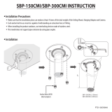
SBP 1000/1500 E (SOL) | SBP 1000-1500 E cool
SBP 1000/1500 E (SOL) | SBP 1000-1500 E cool
D0000083186
1
2
3
14
4
5
15
6
7
9
8
10
17
16
11
SBP 1010E
D0000083591
1
3
14
4
15
6
7
9
8
10
17
16
11
13
12
1 Cover
2 Top thermal insulation section (only WDH cool)
3 Top thermal insulation section
4 Top thermal insulation ring
5 Convection brake (only WDH cool)
6 R.h. thermal insulation section
7 Cover strip
8 Flange thermal insulation ring
9 Connection cover (including insulation)
10 Flange cover
11 Thermal insulation, flange
12 Plastic cover with insulation sections
13 Fleece strip
14 Thermal insulation section, bottom
15 Thermal insulation ring, bottom
16 Rose
17 Left thermal insulation section
On cylinders supplied horizontally, insert the bottom thermal
insulation section inside the support ring, prior to position-
ing the cylinder. Slightly tip the vertically delivered cylinder
in order to position the bottom thermal insulation section.
Surround the support ring with the bottom thermal insula-
tion ring and secure it with adhesive tape.
Remove the foil from the 5 foam strips (convection brakes)
and stick them around the cylinder in the positions shown
(only WDH cool).
Prior to fitting them, shape the right hand and left hand ther-
mal insulation sections into a semi-circular form for approx.
10 seconds. A pressure-activated adhesive then holds the
thermal insulation sections in the required shape and makes
fitting them easier.
Please note that the use of tensioning straps may damage the
thermal insulation.

20 | SBP 1000-1500 E | E SOL | E cool www.stiebel-eltron.com
INSTALLATION
Commissioning
Push the thermal insulation sections over the connections on
the appliance.
Connect the thermal insulation sections at the front by clip-
ping the hook closure strip into the last hook strip. If neces-
sary, the short black cover strips can be used to temporarily
hold the hook closure strips together.
Position the thermal insulation sections around the cylinder
and connect the thermal insulation sections at the back by
clipping the hook closure strip into the first or second hook
strip.
Adjust the thermal insulation sections on the appliance by
patting and pressing them down with the palm of the hand.
Starting from the top, retighten the hook closure strip from
the top until it hooks into the final hook strip.
Place the thermal insulation ring around the flange to com-
pletely fill the gap to the side insulation segments.
Place the thermal insulation ring and the two thermal insula-
tion sections on the top.
Place the cover over the thermal insulation sections.
Fit the cover strips onto the hook closure strips. If required,
the cover strips can be trimmed to size.
Fill the hollow spaces near the connections with the soft
foam inserts.
Push the roses and caps into the apertures.
SBP 1010 E:
Wrap the fleece strip around the neck of the blank flange
(DN80).
Place the plastic cover together with the thermal insulation
onto the blank flange (DN80).
Note
Affix the additional type plate in a clearly visible position
on the thermal insulation.
9.2 Installing the manual air vent valve
26�03�01�0973
Install a manual air vent valve at the air vent valve
connection.
9.3 Fitting the temperature sensor
Fill the protective pipe with heat conducting paste.
Insert the sensor into the protective pipe until it bottoms.
Prior to inserting contact sensor AVF 6 into the protective pipe,
bend the bias spring forward.
9.4 Where appropriate, fit the flanged or threaded
immersion heater.
Remove the dummy flanges and plugs in order to mount
the heat exchanger, flanged or threaded immersion heater.
Maintain the DC separation towards the cylinder.
10. Commissioning
Water quality, solar circuit
A glycol/water mixture of up to 60% is permitted for the indirect
coil in the solar circuit if only dezincification-resistant metals,
glycol-resistant gaskets and diaphragm expansion vessels suitable
for glycol are used throughout the installation.
Oxygen diffusion
!
Material losses
Avoid open heating systems and plastic pipes in under-
floor heating systems which are permeable to oxygen.
In underfloor heating systems with plastic pipes that are per-
meable to oxygen and in open vented heating systems, oxygen
diffusion may lead to corrosion on the steel components of the
heating system (e.g. on the indirect coil of the DHW cylinder, on
buffer cylinders, steel heating elements or steel pipes).
!
Material losses
The products of corrosion (e.g. rusty sludge) can settle in
the heating system components and can result in a lower
output or fault shutdowns due to reduced cross-sections.
!
Material losses
Avoid open vented solar thermal systems and plastic
pipes which are permeable to oxygen.
With plastic pipes that are permeable to oxygen, oxygen diffusion
may lead to corrosion on the steel components of the solar thermal
system (e.g. on the indirect coil of the DHW cylinder).

www.stiebel-eltron.com SBP 1000-1500 E | E SOL | E cool | 21
ENGLISH
INSTALLATION
Shutting down
10.1 Commissioning
!
Material losses
A safety valve is required.
Fill and vent the appliance.
Carry out a tightness check.
Vent the internal indirect coil.
Switch the mains power ON if required.
Check the function of the safety assembly.
Check the function of fitted accessories.
Then check the function of the solar thermal system, if
appropriate.
If relevant, check that the DHW temperature displayed on the
heat source control unit is correct.
10.1.1 Appliance handover
Explain the appliance function to users and familiarise them
with its operation.
Make users aware of potential dangers, especially the risk of
scalding.
Hand over these instructions.
10.2 Recommissioning
See chapter “Commissioning”.
11. Shutting down
If necessary, disconnect any accessories installed from the
mains at the MCB/fuse in the fuse box.
Drain the appliance. See chapter “Maintenance / Draining the
appliance”.
12. Maintenance
No special maintenance is required for the appliance. A regular
visual check is sufficient.
12.1 Draining the appliance
WARNING Burns
Hot water may escape during the draining process.
If the appliance needs to be drained for maintenance or to protect
the whole installation when there is a risk of frost, proceed as
follows:
For draining the appliance, remove the thermal insulation
around the drain connector.

22 | SBP 1000-1500 E | E SOL | E cool www.stiebel-eltron.com
INSTALLATION
Specication
13. Specification
13.1 Dimensions and connections
SBP 1000 E | SBP 1000 E SOL
175175
790
1010
262
522
902
1122
1452
1777
1997
2300
2340
302
277
400
730
827
1060
1390
1650
1800
2050
e01
d36
d02 d36
d25
d01
e02
d35
d35
d26
h22
d46
d47
h43
h22
h22
h28
h02
i07 i07
i01
45°
D0000017390
SBP 1000 E SBP 1000 E SOL
d01 Heat pump flow Nominal diameter DN 80 DN 80
d02 Heat pump return Nominal diameter DN 80 DN 80
d25 Solar flow Female thread G 1
d26 Solar return Female thread G 1
d35 Heat source flow optional Female thread G 1 1/2 G 1 1/2
d36 Heat source return optional Female thread G 1 1/2 G 1 1/2
d46 Ventilation Female thread G 1/2 G 1/2
d47 Drain Male thread G 3/4 A G 3/4 A
e01 Heating flow Nominal diameter DN 80 DN 80
e02 Heating return Nominal diameter DN 80 DN 80
h02 Sensor heat pump return Diameter mm 9.5 9.5
h22 Sensor heat source Diameter mm 9.5 9.5
h28 Sensor solar cylinder Diameter mm 9.5 9.5
h43 Thermometer Diameter mm 14.5 14.5
i01 Flange
Diameter mm 280 280
Pitch circle diameter mm 245 245
Screws M 14 M 14
i07 Electric emergency/booster heater Female thread G 1 1/2 G 1 1/2

www.stiebel-eltron.com SBP 1000-1500 E | E SOL | E cool | 23
ENGLISH
INSTALLATION
Specication
SBP 1010 E
175175
790
1010
262
522
902
1122
1452
1777
1997
2300
1012
2340
302
400
730
1060
1390
1650
1800
2050
i01
i07
i12
h22
h43
d46
h22
h22
h28
h02
d47
d35
d01
d03
d35
e02
d02
d36
d36
e01
45°
D0000083580
SBP 1010 E
d01 Heat pump flow Internal diameter DN 80
d02 Heat pump return Internal diameter DN 80
d03 Heat pump flow optional
Internal diameter DN 80
Pitch circle diameter mm 150
Screws M 16
d35 Heat source flow optional Female thread G 2
d36 Heat source return optional Female thread G 2
d46 Ventilation Female thread G 1/2
d47 Drain Male thread G 3/4 A
e01 Heating flow Internal diameter DN 80
e02 Heating return Internal diameter DN 80
h02 Sensor heat pump return Diameter mm 9,5
h22 Sensor heat source Diameter mm 9,5
h28 Sensor solar cylinder Diameter mm 9,5
h43 Thermometer Diameter mm 14,5
i01 Flange
Diameter mm 280
Pitch circle diameter mm 245
Screws M 14
i07 elec. emergency/booster heater Female thread G 1 1/2
i12 Heat generator, opt. Female thread G 2

24 | SBP 1000-1500 E | E SOL | E cool www.stiebel-eltron.com
INSTALLATION
Specication
SBP 1500 E | SBP 1500 E SOL
175175
1000
1220
349
609
956
1179
1319
1629
1849
2220
2255
389
364
464
759
914
1054
1349
1600
1710
1900
i01
i07
i07
h22
h43
d46
h22
h22
h28
h02
d47
d35
d01
d35
e02
d26
d02
d36
d36
e01
d25
45°
D0000017406
SBP 1500 E SBP 1500 E SOL
d01 Heat pump flow Nominal diameter DN 80 DN 80
d02 Heat pump return Nominal diameter DN 80 DN 80
d25 Solar flow Female thread G 1
d26 Solar return Female thread G 1
d35 Heat source flow optional Female thread G 1 1/2 G 1 1/2
d36 Heat source return optional Female thread G 1 1/2 G 1 1/2
d46 Ventilation Female thread G 1/2 G 1/2
d47 Drain Male thread G 3/4 A G 3/4 A
e01 Heating flow Nominal diameter DN 80 DN 80
e02 Heating return Nominal diameter DN 80 DN 80
h02 Sensor heat pump return Diameter mm 9.5 9.5
h22 Sensor heat source Diameter mm 9.5 9.5
h28 Sensor solar cylinder Diameter mm 9.5 9.5
h43 Thermometer Diameter mm 14.5 14.5
i01 Flange
Diameter mm 280 280
Pitch circle diameter mm 245 245
Screws M 14 M 14
i07 Electric emergency/booster heater Female thread G 1 1/2 G 1 1/2

www.stiebel-eltron.com SBP 1000-1500 E | E SOL | E cool | 25
ENGLISH
INSTALLATION
Specication
SBP 1000 E cool | SBP 1010 E cool
175175
822
1010
262
522
902
1122
1452
1777
1997
2300
2340
302
400
730
1060
1390
1650
1800
2050
i01
i07
i07
h22
h43
d46
h22
h22
h28
h02
d47
d35
d01
d35
e02
d02
d36
d36
e01
45°
D0000017421
SBP 1000 E cool SBP 1010 E cool
d01 Heat pump flow Internal diameter DN 80 DN 80
d02 Heat pump return Internal diameter DN 80 DN 80
d03 Heat pump flow optional Internal diameter DN 80
d35 Heat source flow optional Female thread G 1 1/2 G 1 1/2
d36 Heat source return optional Female thread G 1 1/2 G 1 1/2
d46 Ventilation Female thread G 1/2 G 1/2
d47 Drain Male thread G 3/4 A G 3/4 A
e01 Heating flow Internal diameter DN 80 DN 80
e02 Heating return Internal diameter DN 80 DN 80
h02 Sensor heat pump return Diameter mm 9.5 9.5
h22 Sensor heat source Diameter mm 9.5 9.5
h28 Sensor solar cylinder Diameter mm 9.5 9.5
h43 Thermometer Diameter mm 14.5 14.5
i01 Flange
Diameter mm 280 280
Pitch circle diameter mm 245 245
Screws M 14 M 14
i07 elec. emergency/booster heater Female thread G 1 1/2 G 1 1/2

26 | SBP 1000-1500 E | E SOL | E cool www.stiebel-eltron.com
INSTALLATION
Specication
SBP 1500 E cool
175175
1032
1220
349
609
956
1179
1319
1629
1849
2220
2255
389
464
759
1054
1349
1600
1710
1900
i01
i07
i07
h22
h43
d46
h22
h22
h28
h02
d47
d35
d01
d35
e02
d02
d36
d36
e01
45°
D0000017423
SBP 1500 E cool
d01 Heat pump flow Nominal diameter DN 80
d02 Heat pump return Nominal diameter DN 80
d35 Heat source flow optional Female thread G 1 1/2
d36 Heat source return optional Female thread G 1 1/2
d46 Ventilation Female thread G 1/2
d47 Drain Male thread G 3/4 A
e01 Heating flow Nominal diameter DN 80
e02 Heating return Nominal diameter DN 80
h02 Sensor heat pump return Diameter mm 9.5
h22 Sensor heat source Diameter mm 9.5
h28 Sensor solar cylinder Diameter mm 9.5
h43 Thermometer Diameter mm 14.5
i01 Flange
Diameter mm 280
Pitch circle diameter mm 245
Screws M 14
i07 Electric emergency/booster heater Female thread G 1 1/2
13.2 Fault conditions
In the event of a fault, temperatures of up to 95 °C at 1.0 MPa can
occur depending on the type of heart source used.

www.stiebel-eltron.com SBP 1000-1500 E | E SOL | E cool | 27
ENGLISH
13.3 Data table
SBP 1000 E SBP 1010 E SBP 1500 E SBP 1000 E
SOL
SBP 1500 E
SOL
SBP 1000 E
cool
SBP 1010 E
cool
SBP 1500 E
cool
227564 236569 227565 227566 227567 227588 236570 227589
Hydraulic data
Rated capacity l 1006 1006 1503 979 1473 1006 1006 1503
Capacity, lower indirect coil l 25.9 22.5
Surface area, lower indirect coil m² 3 3.6
Pressure drop at 1.0 m³/h, indirect
coil, bottom
hPa 8 9
Application limits
Max. permissible pressure MPa 0.3 1.0 0.3 0.3 0.3 0.3 1.0 0.3
Test pressure MPa 0.45 1.5 0.45 0.45 0.45 0.45 1.5 0.45
Maximum charge / discharge flow
rate
m³/h 12.5 12.5 15 12.5 15 12.5 12.5 15
Max. permissible temperature °C 95 95 95 95 95 95 95 95
Max. recommended collector aper-
ture area
m² 20 30
Dimensions
Height mm 2300 2300 2220 2300 2220 2300 2300 2220
Height incl. thermal insulation mm 2340 2340 2255 2340 2255 2340 2340 2255
Diameter mm 790 790 1000 790 1000 822 822 1032
Diameter incl. thermal insulation mm 1010 1010 1220 1010 1220 1010 1010 1220
Height of unit when tilted mm 2335 2335 2250 2335 2250 2335 2335 2250
Weights
Weight (wet) kg 1178 1239 1703 1224 1780 1187 1248 1742
Weight (dry) kg 172 233 229 219 285 181 242 239
Guarantee
The guarantee conditions of our German companies do not
apply to appliances acquired outside of Germany. In countries
where our subsidiaries sell our products a guarantee can only
be issued by those subsidiaries. Such guarantee is only grant-
ed if the subsidiary has issued its own terms of guarantee. No
other guarantee will be granted.
We shall not provide any guarantee for appliances acquired in
countries where we have no subsidiary to sell our products.
This will not aect warranties issued by any importers.
Environment and recycling
We would ask you to help protect the environment. After use,
dispose of the various materials in accordance with national
regulations.
GUARANTEE
ENVIRONMENT AND RECYCLING
INSTALLATION | GUARANTEE | ENVIRONMENT AND RECYCLING
Specication

Deutschland
STIEBEL ELTRON GmbH & Co. KG
Dr.-Stiebel-Straße 33 | 37603 Holzminden
Tel. 05531 702-0 | Fax 05531 702-480
info@stiebel-eltron.de
www.stiebel-eltron.de
Verkauf Tel. 05531 702-110 | Fax 05531 702-95108 | info-center@stiebel-eltron.de
Kundendienst Tel. 05531 702-111 | Fax 05531 702-95890 | kundendienst@stiebel-eltron.de
Ersatzteilverkauf Tel. 05531 702-120 | Fax 05531 702-95335 | ersatzteile@stiebel-eltron.de
Irrtum und technische Änderungen vorbehalten! | Subject to errors and technical changes! | Sous réserve
d‘erreurs et de modifications techniques! | Onder voorbehoud van vergissingen en technische wijzigingen!|
Salvo error o modificación técnica! | Excepto erro ou alteração técnica | Zastrzeżone zmiany techniczne i
ewentualne błędy | Omyly a technické změny jsou vyhrazeny! | A muszaki változtatások és tévedések jogát
fenntartjuk! | Отсутствие ошибок не гарантируется. Возможны технические изменения. | Chyby a
technické zmeny sú vyhradené! Stand 9442
Australia
STIEBEL ELTRON Australia Pty. Ltd.
294 Salmon Street | Port Melbourne VIC 3207
Tel. 03 9645-1833 | Fax 03 9645-4366
info@stiebel.com.au
www.stiebel.com.au
Austria
STIEBEL ELTRON Ges.m.b.H.
Gewerbegebiet Neubau-Nord
Margaritenstraße 4 A | 4063 Hörsching
Tel. 07221 74600-0 | Fax 07221 74600-42
info@stiebel-eltron.at
www.stiebel-eltron.at
Belgium
STIEBEL ELTRON bvba/sprl
't Hofveld 6 - D1 | 1702 Groot-Bijgaarden
Tel. 02 42322-22 | Fax 02 42322-12
info@stiebel-eltron.be
www.stiebel-eltron.be
China
STIEBEL ELTRON (Tianjin) Electric Appliance
Co., Ltd.
Plant C3, XEDA International Industry City
Xiqing Economic Development Area
300085 Tianjin
Tel. 022 8396 2077 | Fax 022 8396 2075
info@stiebeleltron.cn
www.stiebeleltron.cn
Czech Republic
STIEBEL ELTRON spol. s r.o.
K Hájům 946 | 155 00 Praha 5 - Stodůlky
Tel. 251116-111 | Fax 235512-122
info@stiebel-eltron.cz
www.stiebel-eltron.cz
Finland
STIEBEL ELTRON OY
Kapinakuja 1 | 04600 Mäntsälä
Tel. 020 720-9988
info@stiebel-eltron.fi
www.stiebel-eltron.fi
France
STIEBEL ELTRON SAS
7-9, rue des Selliers
B.P 85107 | 57073 Metz-Cédex 3
Tel. 0387 7438-88 | Fax 0387 7468-26
info@stiebel-eltron.fr
www.stiebel-eltron.fr
Hungary
STIEBEL ELTRON Kft.
Gyár u. 2 | 2040 Budaörs
Tel. 01 250-6055 | Fax 01 368-8097
info@stiebel-eltron.hu
www.stiebel-eltron.hu
Japan
NIHON STIEBEL Co. Ltd.
Kowa Kawasaki Nishiguchi Building 8F
66-2 Horikawa-Cho
Saiwai-Ku | 212-0013 Kawasaki
Tel. 044 540-3200 | Fax 044 540-3210
info@nihonstiebel.co.jp
www.nihonstiebel.co.jp
Netherlands
STIEBEL ELTRON Nederland B.V.
Daviottenweg 36 | 5222 BH 's-Hertogenbosch
Tel. 073 623-0000 | Fax 073 623-1141
info@stiebel-eltron.nl
www.stiebel-eltron.nl
Poland
STIEBEL ELTRON Polska Sp. z O.O.
ul. Działkowa 2 | 02-234 Warszawa
Tel. 022 60920-30 | Fax 022 60920-29
biuro@stiebel-eltron.pl
www.stiebel-eltron.pl
Russia
STIEBEL ELTRON LLC RUSSIA
Urzhumskaya street 4,
building 2 | 129343 Moscow
Tel. 0495 7753889 | Fax 0495 7753887
info@stiebel-eltron.ru
www.stiebel-eltron.ru
Slovakia
TATRAMAT - ohrievače vody s.r.o.
Hlavná 1 | 058 01 Poprad
Tel. 052 7127-125 | Fax 052 7127-148
info@stiebel-eltron.sk
www.stiebel-eltron.sk
Switzerland
STIEBEL ELTRON AG
Industrie West
Gass 8 | 5242 Lupfig
Tel. 056 4640-500 | Fax 056 4640-501
info@stiebel-eltron.ch
www.stiebel-eltron.ch
Thailand
STIEBEL ELTRON Asia Ltd.
469 Moo 2 Tambol Klong-Jik
Amphur Bangpa-In | 13160 Ayutthaya
Tel. 035 220088 | Fax 035 221188
info@stiebeleltronasia.com
www.stiebeleltronasia.com
United Kingdom and Ireland
STIEBEL ELTRON UK Ltd.
Unit 12 Stadium Court
Stadium Road | CH62 3RP Bromborough
Tel. 0151 346-2300 | Fax 0151 334-2913
info@stiebel-eltron.co.uk
www.stiebel-eltron.co.uk
United States of America
STIEBEL ELTRON, Inc.
17 West Street | 01088 West Hatfield MA
Tel. 0413 247-3380 | Fax 0413 247-3369
info@stiebel-eltron-usa.com
www.stiebel-eltron-usa.com
A 283831-41341-9456
4<AMHCMN=ididba>
/