SICK V200 Work Station Extended, V300 Work Station Extended Operating instructions
- Type
- Operating instructions

OPERATING INSTRUCTIONS
V200 Work Station Extended,
V300 Work Station Extended
Safety camera system
en

Operating Instructions
V200/V300
2 © SICK AG • Industrial Safety Systems • Germany • All rights reserved 8012227/YT87/2016-03-29
Subject to change without notice
This document is protected by the law of copyright, whereby all rights established therein remain with the
company SICK AG. Reproduction of this document or parts of this document is only permissible within the limits
of the legal determination of Copyright Law. Alteration or abridgement of the document is not permitted without
the explicit written approval of the company SICK AG.

Operating Instructions
V200/V300
8012227/YT87/2016-03-29 © SICK AG • Industrial Safety Systems • Germany • All rights reserved 3
Subject to change without notice
Contents
Contents
1 About this document.................................................................................................... 5
1.1 Function of this document................................................................................5
1.2 Target group .....................................................................................................5
1.3 Information depth............................................................................................. 5
1.4 Scope................................................................................................................6
1.5 Abbreviations used...........................................................................................6
1.6 Symbols used ...................................................................................................6
2 On safety.......................................................................................................................8
2.1 Qualified safety personnel................................................................................8
2.2 Applications of the device.................................................................................9
2.3 Correct use .......................................................................................................9
2.4 General safety notes and protective measures..............................................10
2.5 Environmental protection ...............................................................................11
2.5.1 Disposal.........................................................................................11
2.5.2 Separation of materials.................................................................11
3 Product description....................................................................................................12
3.1 Special features..............................................................................................12
3.2 Operating principle of the device....................................................................12
3.3 Application examples......................................................................................13
3.4 Configurable functions....................................................................................14
3.4.1 Restart interlock............................................................................14
3.4.2 External device monitoring (EDM) .................................................15
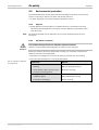
3.5 Status indicators.............................................................................................16
3.5.1 Status LEDs of the V200/V300.....................................................16
3.5.2 Diagnostics LEDs of the V200/V300.............................................17
4 Mounting ....................................................................................................................18
4.1 Checking the dimensions of the protective field.............................................18
4.1.1 Protective field dimensions allowed at a resolution of
20 mm...........................................................................................18
4.1.2 Protective field dimensions allowed at a resolution of
24 mm...........................................................................................19
4.1.3 Protective field dimensions allowed at a resolution of
30 mm...........................................................................................19
4.2 Determining the minimum distance ...............................................................20
4.2.1 Minimum distance according to EN ISO 13 855 and
EN ISO 13 857...............................................................................21
4.2.2 Minimum distance if OSHA and ANSI are applicable.....................23
4.3 Avoiding unmonitored areas...........................................................................24
4.4 Steps for mounting the safety camera system ...............................................26
4.4.1 Mounting on a frame.....................................................................27
4.4.2 Mounting in a frame ......................................................................28
4.4.3 Mounting the reflective tape .........................................................29
5 Electrical installation.................................................................................................31
5.1 System connection M12 × 8 ...........................................................................32
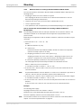
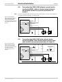
5.2 Connecting the V200/V300 without external device monitoring (EDM),
without internal restart interlock and without external key-operated
pushbutton for teach-in ..................................................................................33

Operating Instructions
V200/V300
4 © SICK AG • Industrial Safety Systems • Germany • All rights reserved 8012227/YT87/2016-03-29
Subject to change without notice
Contents
5.3 Connecting the V200/V300 with external device monitoring (EDM),
with internal restart interlock and with external key-operated
pushbutton for teach-in.................................................................................. 33
5.4 Two V200/V300 with synchronisation........................................................... 35
5.5 Connection diagrams ..................................................................................... 36
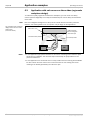
5.5.1 V200/V300 on UE410 Flexi with external device monitoring
(EDM) and with restart interlock both for V200/V300 as well
as for emergency switching off ..................................................... 36
5.5.2 V200/V300 on UE10-3OS with external device monitoring
(EDM) and internal restart interlock ............................................. 37
6 Application examples ................................................................................................ 38
6.1 Application with one V200/V300................................................................... 38
6.2 Application with two V200/V300................................................................... 39
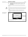
6.3 Application with safe access on three sides (ergonomic workplace
design) ........................................................................................................... 40
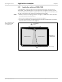
6.4 Application with automatic material transport to the workstation ................. 41
7 Commissioning .......................................................................................................... 42
7.1 Test notes ...................................................................................................... 42
7.2 Tests before the initial commissioning .......................................................... 42
7.3 Regular inspection of the protective device by qualified safety
personnel....................................................................................................... 42
7.4 Tests of the protective device by a specialist or authorised personnel.......... 43
8 Configuration ............................................................................................................. 44
8.1 Teach-in ......................................................................................................... 44
8.2 Internal restart interlock ................................................................................ 46
8.3 External device monitoring............................................................................. 47
8.4 Locking the internal teach-in key................................................................... 48
9 Care and maintenance .............................................................................................. 49
10 Fault diagnosis .......................................................................................................... 50
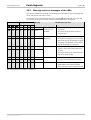
10.1 In the event of faults or errors ....................................................................... 50
10.2 SICK support .................................................................................................. 50
10.3 Warnings and error messages of the LEDs.................................................... 51
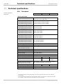
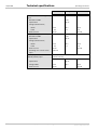
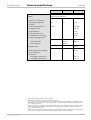
11 Technical specifications............................................................................................ 52
11.1 Data sheet ..................................................................................................... 52
11.2 Dimensional drawings.................................................................................... 56
11.2.1 Dimensional drawing V200/V300 ................................................ 56
11.2.2 Dimensional drawing, mounting kit .............................................. 57
12 Ordering information ................................................................................................. 58
12.1 Safety camera systems.................................................................................. 58
12.2 Accessories.................................................................................................... 59
13 Annex ......................................................................................................................... 60
13.1 Compliance with EU directives....................................................................... 60
13.2 Checklist for the manufacturer ...................................................................... 61
13.3 List of tables .................................................................................................. 62
13.4 List of illustrations.......................................................................................... 62

Operating Instructions Chapter 1
V200/V300
8012227/YT87/2016-03-29 © SICK AG • Industrial Safety Systems • Germany • All rights reserved 5
Subject to change without notice
About this document
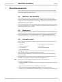
1 About this document
Please read this chapter carefully before working with the documentation and the V200
Work Station Extended or V300 Work Station Extended safety camera system, referred to
in the following as V200/V300 for short.
1.1 Function of this document
These operating instructions are designed to address the technical personnel of the
machine manufacturer or the machine operator in regards to safe mounting, installation,
configuration, electrical installation, commissioning, operation and maintenance of the
V200/V300 safety camera system.
These operating instructions do not provide instructions for operating machines on which
the safety camera system is, or will be, integrated. Information on this is to be found in the
operating instructions for the machine.
1.2 Target group
These operating instructions are addressed to planning engineers, machine designers and
operators of plants and systems which are to be protected by one or several V200/V300
safety camera systems. It also addresses people who integrate the V200/V300 into a
machine, initialise its use, or who are in charge of servicing and maintaining the device.
1.3 Information depth
These operating instructions contain the following information on the V200/V300 safety
camera system:
• mounting
• electrical installation
• commissioning
• care and maintenance
• fault diagnosis and troubleshooting
• part numbers
• conformity and approval
Planning and using protective devices such as the V200/V300 also require specific
technical skills which are not detailed in this documentation.
When operating the V200/V300, the national, local and statutory rules and regulations
must be observed.
General information on accident prevention using opto-electronic protective devices can
be found in the competence brochure “Guidelines Safe Machinery”.
Please refer also to the SICK homepage on the Internet at www.sick.com.
Here you will find information on:
• application examples and application reports that supplement the application examples
in chapter 6
• a list of frequently asked questions regarding the V200/V300
• these operating instructions in different languages for viewing and printing
• certificates on the prototype test, the EU declaration of conformity and other documents
Note

Chapter 1 Operating Instructions
V200/V300
6 © SICK AG • Industrial Safety Systems • Germany • All rights reserved 8012227/YT87/2016-03-29
Subject to change without notice
About this document
1.4 Scope
This document is an original document.
These operating instructions are only applicable to the V200/V300 safety camera system
with one of the following entries on the type label in the field Operating Instructions:
• 8012225 XF85
• 8012225 YY28
• 8012225 YT87
This document is part of SICK part number 8012225 (operating instructions “V200/V300
– Safety camera system” in all available languages).
1.5 Abbreviations used
American National Standards Institute
External device monitoring
Electro-sensitive protective equipment (e.g. V200/V300)
Light Emitting Diode
Output signal switching device = signal output from the protective device to the controller
that is used to stop the dangerous movement
Short code for the V200 Work Station Extended/V300 Work Station Extended
safety camera system
1.6 Symbols used
Recommendations are designed to give you some assistance in your decision-making
process with respect to a certain function or a technical measure.
Refer to notes for special features of the device.
LED symbols describe the status of an LED. Examples:
o The LED is off.
O The LED is illuminated constantly.
ôFõ The LED flashes evenly (0.5 seconds on, 0.5 seconds off).
ôJõ The LED goes off briefly (0.9 seconds on, 0.1 seconds off, …).
ôKõ The LED flashes with a short duty cycle (0.9 seconds off, 0.1 seconds on, …).
In combination with the LED symbols, these symbols identify which LED is described:
Ê O The LED “Stop” (OSSDs switched off) is illuminated constantly.
É ôFõ The LED “Warning” flashes.
Ë o The LED “OK” (OSSDs switched on) is off.
Instructions for taking action are shown by an arrow. Read carefully and follow the
instructions for action.
Warning!
A warning notice indicates an actual or potential risk or health hazard. They are designed
to help you to prevent accidents.
Read carefully and follow the warning notices!
Notes
ANSI
EDM
ESPE
LED
OSSD
V200/V300
Recommendation
Note
o
,
O
,
ôFõ
,
ôKõ
,
ôJõ
Ê É Ë
> Take action …
a
WARNING

Operating Instructions Chapter 1
V200/V300
8012227/YT87/2016-03-29 © SICK AG • Industrial Safety Systems • Germany • All rights reserved 7
Subject to change without notice
About this document
The term “dangerous state”
The dangerous state (standard term) of the machine is always shown in the drawings and
diagrams of this document as a movement of a machine part. In practical operation, there
may be a number of different dangerous states:
• machine movements
• electrical conductors
• visible or invisible radiation
• a combination of several risks and hazards

Chapter 2 Operating Instructions
V200/V300
8 © SICK AG • Industrial Safety Systems • Germany • All rights reserved 8012227/YT87/2016-03-29
Subject to change without notice
On safety
2 On safety
This chapter deals with your own safety and the safety of the equipment operators.
⋅ Please read this chapter carefully before working with the V200/V300 or with the
machine protected by the V200/V300.
2.1 Qualified safety personnel
The V200/V300 safety camera system must only be installed, commissioned and serviced
by qualified safety personnel. Qualified safety personnel are defined as persons who
• due to their specialist training and experience have adequate knowledge of the power-
driven equipment to be checked
and
• have been instructed by the responsible machine owner in the operation of the machine
and the current valid safety guidelines
and
• are sufficiently familiar with the applicable official health and work safety regulations,
directives and generally recognized engineering practice (e.g. DIN standards, VDE
stipulations, engineering regulations from other EU member states) that they can
assess the work safety aspects of the power-driven equipment
and
• have access to these operating instructions and have read them.
As a rule these are qualified safety personnel from the ESPE manufacturer or also persons
who have been appropriately trained at the ESPE manufacturer, are primarily involved in
checking ESPE and are allocated the task by the organisation operating the ESPE.

Operating Instructions Chapter 2
V200/V300
8012227/YT87/2016-03-29 © SICK AG • Industrial Safety Systems • Germany • All rights reserved 9
Subject to change without notice
On safety
2.2 Applications of the device
The V200/V300 safety camera system is an item of electro-sensitive protective equipment
(ESPE).
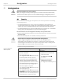
The V200/V300 safety camera system can be operated with 3 resolutions. Depending on
the resolution used, the maximum protective field dimensions change:
Protective field dimensions [m]Resolution
[mm]
Minimum Maximum Note
20 0.40 × 0.40 1.00 × 1.00
24 0.40 × 0.40 1.20 × 1.20
30 0.60 × 0.60 1.50 × 1.50
On sizing the protective field the
ratio for the lengths of the sides
must be considered (see section 4.1
“Checking the dimensions of the
protective field” on page 18 ff.)
The device is a Type 3 ESPE (V300 Work Station Extended) or a Type 2 (V200 Work Station
Extended) according to IEC 61 496-1 and IEC/TR 61 496-4 and is therefore allowed for use
with controls in category 3 according to EN ISO 13 849-1. The device is suitable for
hazardous point protection (hand protection).
Access to the hazardous point must be allowed only through the protective field. As long as
the hazardous point is occupied, the system must not start. Refer to section 3.3
“Application examples” on page 13 for an illustration of the protection modes.
Only use the safety camera system as an indirect protective measure!
An opto-electronic protective device provides indirect protection, e.g. by switching off the
power at the source of the hazard. It cannot provide protection from parts thrown out, nor
from emitted radiation. Transparent objects are not detected.
Depending on the application, mechanical guards may be required in addition to the safety
camera system.
The safety camera system is only intended for use in industrial environments. When used
in residential areas it can cause radio interferences.
2.3 Correct use
The V200/V300 safety camera system must be used only as defined in section 2.2
“Applications of the device”. It must be used only by qualified personnel and only on the
machine where it has been installed and initialised by qualified safety personnel in
accordance with these operating instructions.
If the device is used for any other purposes or modified in any way — also during mounting
and installation — any warranty claim against SICK AG shall become void.
Tab.
1
:
Maximum protective
field dimensions as a
function of the resolution
a
WARNING

Chapter 2 Operating Instructions
V200/V300
10 © SICK AG • Industrial Safety Systems • Germany • All rights reserved 8012227/YT87/2016-03-29
Subject to change without notice
On safety
2.4 General safety notes and protective measures
Pay attention to the safety notes!
Please observe the following procedures in order to ensure the correct and safe use of the
V200/V300 safety camera system.
• The national/international rules and regulations apply to the installation, use and
periodic technical inspections of the safety camera system, in particular:
– Machinery Directive
– Work Equipment Directive
– the work safety regulations/safety rules
– other relevant safety regulations
Manufacturers and operators of the machine on which the safety camera system is used
are responsible for obtaining and observing all applicable safety regulations and rules.
• The notices, in particular the test regulations (see section 7.1 “Test notes” on page 42)
of these operating instructions (e.g. on use, mounting, installation or integration into the
existing machine controller) must be observed.
• The tests must be carried out by qualified safety personnel or specially qualified and
authorised personnel and must be recorded and documented to ensure that the tests
can be reconstructed and retraced at any time.
• Changes to the configuration of the devices can degrade the protective function. After
every change to the configuration you must therefore check the effectiveness of the
protective device. The person who makes the change is also responsible for the correct
protective function of the device.
• The light beams from the camera may be deflected by reflective surfaces. This can
result in failure to identify an object. For this reason reflective surfaces on the reflective
tape or in the protective field are not allowed.
• The operating instructions must be made available to the operator of the machine where
the V200/V300 safety camera system is fitted. The machine operator is to be instructed
in the use of the device by qualified safety personnel and must be instructed to read the
operating instructions.
• To meet the requirements of the relevant product standards (e.g. IEC 61 496-1), the
external voltage supply for the devices (SELV) must be able to bridge a brief mains
failure of 20 ms. Power supplies according to EN 60 204-1 satisfy this requirement.
Suitable power supplies are available as accessories from SICK (see section 12.2
“Accessories” on page 59).
a
WARNING

Operating Instructions Chapter 2
V200/V300
8012227/YT87/2016-03-29 © SICK AG • Industrial Safety Systems • Germany • All rights reserved 11
Subject to change without notice
On safety
2.5 Environmental protection
The V200/V300 safety camera system has been designed to minimise environmental
impact. It uses only a minimum of power and natural resources.
⋅ At work, always act in an environmentally responsible manner.
2.5.1 Disposal
⋅ Always dispose of unserviceable or irreparable devices in compliance with local/
national rules and regulations with respect to waste disposal (e.g. European waste
code 16 02 14).
We would be pleased to be of assistance to you on the disposal of these devices.
Contact us.
2.5.2 Separation of materials
Only qualified safety personnel are allowed to separate materials!
Caution is required when dismantling devices. There is a risk of injuries.
Before you send the devices for appropriate recycling, it is necessary to separate the
different materials in the V200/V300.
⋅ Separate the housing from the rest of the parts (in particular the circuit board).
⋅ Send the separated parts for recycling as appropriate:
Components Disposal
Product
Housing Metal recycling (aluminium)
Circuit boards, cable, connector and
electrical connecting pieces
Electronic recycling
Packaging
Cardboard, paper Paper/cardboard recycling
Polyethylene packaging Plastic recycling
Note
a
WARNING
Tab.
2
:
Overview on disposal
by components

Chapter 3 Operating Instructions
V200/V300
12 © SICK AG • Industrial Safety Systems • Germany • All rights reserved 8012227/YT87/2016-03-29
Subject to change without notice
Product description
3 Product description
This chapter provides information on the special features and properties of the
V200/V300 safety camera system. It describes the construction and the operating
principle of the device, in particular the different operating modes.
⋅ Please read this chapter before mounting, installing and commissioning the device.
3.1 Special features
• V200 Work Station Extended: Type 2 ESPE according to IEC 61 496-1
• V300 Work Station Extended: Type 3 ESPE according to IEC 61 496-1
complies with the requirements for the “Control reliable” safety level.
• protective operation with either internal or external (realised on the machine)
restart interlock
• facility for connecting a reset button
• facility for connecting an external device monitoring (EDM)
• status indication by LED
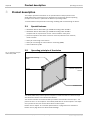
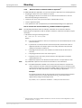
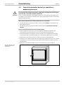
3.2 Operating principle of the device
The V200/V300 safety camera system comprises a camera as well as a reflective tape
with which the contour to be monitored is defined.
The camera monitors the area bounded by its field of view and the reflective tape – the
protective field – for interruptions. If the V200/V300 detects an interruption in the shape
of the protective field, the camera shuts down its safe outputs.
Please refer to chapter 11 “Technical specifications” on page 52 for the data sheet.
Please refer to page 56 for the dimensional drawings.
Fig.
1
:
Operating principle
of the V200/V300
Camera
Reflective tape on the
members opposite the
camera
Protective field
Machine
-
side moun
ting
profile

Operating Instructions Chapter 3
V200/V300
8012227/YT87/2016-03-29 © SICK AG • Industrial Safety Systems • Germany • All rights reserved 13
Subject to change without notice
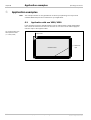
Product description
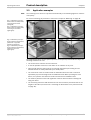
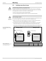
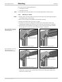
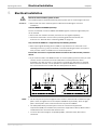
3.3 Application examples
The mounting of the device is only shown schematically in the following figures for reasons
of simplicity.
For correct mounting, pay attention to the notes in chapter 4 “Mounting” on page 18.
The V200/V300 safety camera system operates correctly as a protective device only if the
following conditions are met:
• The control of the machine must be electrical.
• It must be possible to achieve a safe state on the machine at any time.
• Camera and reflective tape must be so mounted that objects penetrating into the
hazardous area are safely identified by the V200/V300.
• The reset button must be fitted outside the hazardous area such that it cannot be
operated by a person working inside the hazardous area. When operating the reset
button, the operator must have full visual command of the hazardous area.
• The statutory and local rules and regulations must be observed when installing and
using the device.
• The necessary protective field dimensions must not exceed the permitted ratio for the
lengths of the sides (see section 4.1 “Checking the dimensions of the protective field”
on page 18).
Note
Fig.
2
:
Hazardous point pro
-
tection with one V200/V300,
mounting in the frame
(left figure)
Fig. 3: Hazardous point pro-
tection with one V200/V300,
mounting on the frame
(right figure)
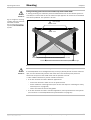
Fig.
4
:
Hazardous point pro
-
tection with two V200/V300,
placement in opposite
directions (left figure)
Fig. 5: Hazardous point pro-
tection with two V200/V300,
placement at corner
(right figure)

Chapter 3 Operating Instructions
V200/V300
14 © SICK AG • Industrial Safety Systems • Germany • All rights reserved 8012227/YT87/2016-03-29
Subject to change without notice
Product description
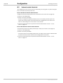
3.4 Configurable functions
This section describes the functions of the V200/V300 safety camera system that can be
configured.
Test the protective device after any changes!
After each modification to the protective device or its connection, you must check the
whole protective device for effectiveness (see section 7.1 “Test notes” on page 42).
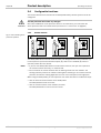
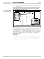
3.4.1 Restart interlock
The V200/V300 has an internal restart interlock. The dangerous state of the machine (1)
is interrupted on a protective field interruption (2), and is not re-enabled (3) until the
operator presses the reset button.
• If you use the V200/V300 without internal restart interlock, then you must implement
the restart interlock externally, i.e. machine-side.
• Do not confuse the restart interlock with the starting interlock on the machine. The
starting interlock prevents the machine starting after switching on. The restart interlock
prevents the machine starting again after an error or an interruption of the light path.
When using the V200/V300, you can implement the restart interlock in two different ways:
• with the internal restart interlock of the V200/V300:
The V200/V300 controls the restart.
• with the restart interlock of the machine (external):
The V200/V300 has no control over the restart.
a
WARNING
Fig.
6
:
Outline drawing of the
protective operation
Notes

Operating Instructions Chapter 3
V200/V300
8012227/YT87/2016-03-29 © SICK AG • Industrial Safety Systems • Germany • All rights reserved 15
Subject to change without notice
Product description
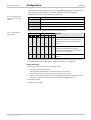
The possible combinations are shown in the following table:
Restart interlock
of the V200/V300
Restart interlock
of the machine
Permissible
application
Deactivated Deactivated Only if …
• the safety camera system cannot be
stood behind. Observe EN 60 204-1!
• it is ensured no work clothing with
reflectors is used.
Deactivated Activated All
Activated Deactivated
Only if the safety camera system cannot
be stood behind. Observe EN 60 204-1!
Activated Activated
All. Restart interlock of the V200/V300
handles the reset function (see “Reset”
below).
Always configure the application with restart interlock!
Ensure that there is always a restart interlock. The V200/V300 is unable to verify if the
restart interlock of the machine is connected. If you deactivate both the internal and the
external restart interlock, the users and operators of the machine will be at acute risk of
injury.
Reset
If you activate the restart interlock on the V200/V300 (internal) and also realise a restart
interlock on the machine (external), then each restart interlock gets its own button.
When actuating the reset button (for the internal restart interlock) …
• the V200/V300 activates the output signal switching devices.
• switches the V200/V300 to green.
Only the external restart interlock prevents the machine from restarting. After pressing the
reset button for the V200/V300, the operator must also press the restart button for the
machine. If the reset button and the restart button are not pressed in the specified
sequence, the dangerous state must remain disrupted.
The reset button prevents the accidental and inadvertent operation of the external restart
button. The operator must first acknowledge the safe state with the reset button.
The electrical connection of the reset button is described in section 5.3 on page 33. The
configuration of the internal restart interlock is described in section 8.2 “Internal restart
interlock” on page 46.
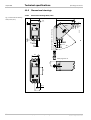
3.4.2 External device monitoring (EDM)
The V200/V300 has external device monitoring. If you activate the external device
monitoring, then the V200/V300 checks whether the contactors are actually de-energized
when the protective device triggers. If, after an attempted Reset/restart, the EDM does not
detect a response from the switched device within 300 ms, the EDM will deactivate the
output signal switching devices again. In this case the safety camera system signals as
follows:
• The system remains at red. The status LED Ê O illuminates.
• The status LED É ôKõ flashes with a short duty cycle
• The diagnostics LED 2 ôKõ flashes with a short duty cycle.
Tab.
3
:
Permissible restart
interlock configurations
on the V200/V300
a
WARNING
Recommendation

Chapter 3 Operating Instructions
V200/V300
16 © SICK AG • Industrial Safety Systems • Germany • All rights reserved 8012227/YT87/2016-03-29
Subject to change without notice
Product description
If the system is unable to change to a safe operational state (e.g. after contactor failure),
the system locks and shuts down completely (“lock-out”, see page 50). The electrical
connection for the external device monitoring is described in section 5.3 on page 33. The
configuration of the external device monitoring is described in chapter 8 “Configuration”
on page 44.
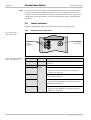
3.5 Status indicators
The light emitting diodes (LEDs) on the V200/V300 signal its operating status.
3.5.1 Status LEDs of the V200/V300
Display Colour Meaning
Ê O
Red
OSSDs shut down (e.g. if object in protective field or
“lock-out”)
Ë O
Green OSSDs activated. Protective field unoccupied
É O
No valid configuration taught-in (default delivery status)
⋅ Perform the teach-in procedure (see section 8.1
“Teach-in” on page 44).
É ôFõ
Even flashing: reset required
⋅ Press the reset button.
É ôJõ
Warning
⋅ Carry out a fault diagnosis (see chapter 10 “Fault
diagnosis” on page 50).
É ôKõ
Yellow
Error
⋅ Carry out a fault diagnosis (see chapter 10 “Fault
diagnosis” on page 50).
Note
Fig.
7
:
Status LEDs
of the V200/V300
Tab.
4
:
Meaning of the status
LEDs of the V200/V300
Status LEDs
Ê “Stop”
É “Warning”
Ë “OK”
Internal
teach-in key

Operating Instructions Chapter 3
V200/V300
8012227/YT87/2016-03-29 © SICK AG • Industrial Safety Systems • Germany • All rights reserved 17
Subject to change without notice
Product description
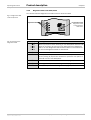
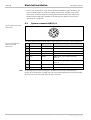
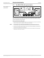
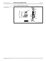
3.5.2 Diagnostics LEDs of the V200/V300
The camera indicates diagnostic information with the aid of four LEDs.
Display Meaning
O 1
… O 2
… O 3
… O 4
Power-up sequence: After switching on the V200/V300 and after each
teach-in, the power up sequence runs. Starting with the diagnostics
LED 1, the next diagnostics LED illuminates after one second and so
on until all 4 diagnostics LEDs are illuminated.
o Protective field sector free
O
Interruption of the protective field in the allocated protective field
sector (see Fig. 8). A protective field sector represents one quarter of
the field of view of the V200/V300.
ôFõ Teach-in mode (see section 8.1 “Teach-in” on page 44)
ôJõ Warning (see chapter 10 “Fault diagnosis” on page 50)
ôKõ Error (see chapter 10 “Fault diagnosis” on page 50)
Fig.
8
:
Diagnostics LEDs
of the V200/V300
Tab.
5
:
Meaning of the
diagnostics LEDs
Diagnostics LEDs
Allocation of the
diagnostics LEDs
to the protective
field sector

Chapter 4 Operating Instructions
V200/V300
18 © SICK AG • Industrial Safety Systems • Germany • All rights reserved 8012227/YT87/2016-03-29
Subject to change without notice
Mounting
4 Mounting
This chapter describes the preparation and completion of the mounting of the V200/V300
safety camera system. Mounting requires the following steps:
• checking the dimensions of the protective field (see below)
• determining the minimum distance (see page 20)
• mounting of the camera (see page 24)
• mounting the reflective tape (see page 29)
The following steps are necessary after mounting:
• completing the electrical connections (see chapter 5 on page 31)
• testing the installation (see section 7.1 on page 42)
4.1 Checking the dimensions of the protective field
Only use the V200/V300 safety camera system if the ratio allowed for the lengths of
the sides of the protective field can be met!
If the maximum ratio of the lengths of the sides is exceeded, the safety camera system
may not operate correctly. This would mean that the operator is at risk.
Applicable to all resolutions:
• The ratio of the lengths of the sides of a protective field monitored must not exceed 2:1.
• If you require a larger protective field than is possible with a single V200/V300, you can
mount two V200/V300 in parallel in opposite directions. In this way you can generate
two overlapping protective fields (see 6.2 “Application with two V200/V300” on
page 39).
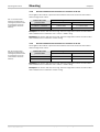
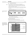
4.1.1 Protective field dimensions allowed at a resolution of 20 mm
The lengths of the sides of a protective field monitored must not be shorter than 0.40 m
and not longer than 1.00 m.
Longer side of the protective field
Shorter side of the
protective field
Minimum Maximum
″ 0.40 m … < 0.50 m = shorter side 2 × shorter side
″ 0.50 m … ′ 1.00 m = shorter side 1.00 m
Example 1: The shorter side is 0.43 m long. Then the longer side must be at least 0.43 m
and is allowed to be a maximum of 2 × 0.43 m = 0.86 m long.
Example 2: The shorter side is 0.78 m long. Then the longer side must be at least 0.78 m
and is allowed to be a maximum of 1.00 m long.
a
WARNING
Note
Tab.
6
:
Protective field
dimensions allowed for a
rectangular protective field
at a resolution of 20 mm
(intermediate values are
allowed)

Operating Instructions Chapter 4
V200/V300
8012227/YT87/2016-03-29 © SICK AG • Industrial Safety Systems • Germany • All rights reserved 19
Subject to change without notice
Mounting
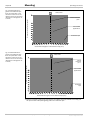
4.1.2 Protective field dimensions allowed at a resolution of 24 mm
The lengths of the sides of a protective field monitored must not be shorter than 0.40 m
and not longer than 1.20 m.
Longer side of the protective field
Shorter side of the
protective field
Minimum Maximum
″ 0.40 m … < 0.60 m = shorter side 2 × shorter side
″ 0.60 m … ′ 1.20 m = shorter side 1.20 m
Example 1: The shorter side is 0.43 m long. Then the longer side must be at least 0.43 m
and is allowed to be a maximum of 2 × 0.43 m = 0.86 m long.
Example 2: The shorter side is 0.78 m long. Then the longer side must be at least 0.78 m
and is allowed to be a maximum of 1.20 m long.
4.1.3 Protective field dimensions allowed at a resolution of 30 mm
The lengths of the sides of a protective field monitored must not be shorter than 0.60 m
and not longer than 1.50 m.
Longer side of the protective field
Shorter side of the
protective field
Minimum Maximum
″ 0.60 m … < 0.75 m = shorter side 2 × shorter side
″ 0.75 m … ′ 1.50 m = shorter side 1.50 m
Example 1: The shorter side is 0.63 m long. Then the longer side must be at least 0.63 m
and is allowed to be a maximum of 2 × 0.63 m = 1.26 m long.
Example 2: The shorter side is 0.78 m long. Then the longer side must be at least 0.78 m
and is allowed to be a maximum of 1.50 m long.
Tab.
7
:
Protective field
dimensions allowed for a
rectangular protective field
at a resolution of 24 mm
(intermediate values are
allowed)
Tab.
8
:
Protective field
dimensions allowed for a
rectangular protective field
at a resolution of 30 mm
(intermediate values are
allowed)

Chapter 4 Operating Instructions
V200/V300
20 © SICK AG • Industrial Safety Systems • Germany • All rights reserved 8012227/YT87/2016-03-29
Subject to change without notice
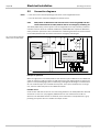
Mounting
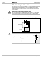
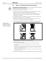
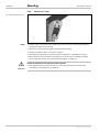
4.2 Determining the minimum distance
The safety camera system must be mounted with an adequate minimum distance between
the protective field and the hazardous point. This minimum distance ensures that the
hazardous point can only be reached after the dangerous state of the machine has been
completely stopped.
No protective function without sufficient minimum distance!
The reliable protective effect of the safety camera system depends on the safety camera
system being mounted with the correct minimum distance from the hazardous point.
If mounted vertically, the protective field is from the centre of the camera lens to the edge
of the reflective tape that is closest to the hazardous point. (The reference point for the
minimum distance S is therefore not the middle of the reflective tape. Cf. Fig. 9.)
If the protective field is at an angle, pay special attention to the minimum distance!
Ensure the necessary minimum distance between the
access point and the hazardous point is met at all parts of
the protective field at an angle.
⋅ Note that different rules may apply to the calculation of
the minimum distance for protective fields at an angle.
⋅ Your SICK-
subsidiary will be pleased to assist you with the
implementation of special applications.
a
WARNING
Note
Fig.
9
:
Minimum distance
from the hazardous point
a
WARNING
Hazardous
point
Minimum dista
nce S (D
s
)
Protective field
height
All
-
round
reflective tape
S (D
s
)
Page is loading ...
Page is loading ...
Page is loading ...
Page is loading ...
Page is loading ...
Page is loading ...
Page is loading ...
Page is loading ...
Page is loading ...
Page is loading ...
Page is loading ...
Page is loading ...
Page is loading ...
Page is loading ...
Page is loading ...
Page is loading ...
Page is loading ...
Page is loading ...
Page is loading ...
Page is loading ...
Page is loading ...
Page is loading ...
Page is loading ...
Page is loading ...
Page is loading ...
Page is loading ...
Page is loading ...
Page is loading ...
Page is loading ...
Page is loading ...
Page is loading ...
Page is loading ...
Page is loading ...
Page is loading ...
Page is loading ...
Page is loading ...
Page is loading ...
Page is loading ...
Page is loading ...
Page is loading ...
Page is loading ...
Page is loading ...
Page is loading ...
Page is loading ...
-
 1
1
-
 2
2
-
 3
3
-
 4
4
-
 5
5
-
 6
6
-
 7
7
-
 8
8
-
 9
9
-
 10
10
-
 11
11
-
 12
12
-
 13
13
-
 14
14
-
 15
15
-
 16
16
-
 17
17
-
 18
18
-
 19
19
-
 20
20
-
 21
21
-
 22
22
-
 23
23
-
 24
24
-
 25
25
-
 26
26
-
 27
27
-
 28
28
-
 29
29
-
 30
30
-
 31
31
-
 32
32
-
 33
33
-
 34
34
-
 35
35
-
 36
36
-
 37
37
-
 38
38
-
 39
39
-
 40
40
-
 41
41
-
 42
42
-
 43
43
-
 44
44
-
 45
45
-
 46
46
-
 47
47
-
 48
48
-
 49
49
-
 50
50
-
 51
51
-
 52
52
-
 53
53
-
 54
54
-
 55
55
-
 56
56
-
 57
57
-
 58
58
-
 59
59
-
 60
60
-
 61
61
-
 62
62
-
 63
63
-
 64
64


SICK V200 Work Station Extended, V300 Work Station Extended Operating instructions
- Type
- Operating instructions
Ask a question and I''ll find the answer in the document
Finding information in a document is now easier with AI
Related papers
-
SICK V200 Work Station Extended, V300 Work Station Extended Quickstart
-
-
-
-
-
-
-
-
-
Other documents
-
Toshiba V200 User manual
-
Emerson V150 User guide
-
Fujitsu S26361-F3986-L1 Datasheet
-
Eaton Vikers V400 Series Overhaul Manual
-
Watlow DIN-A-MITE User manual
-
Draper V180-W Datasheet
-
Altronix Trove T1VK3F4 Installation guide
-
Altronix Trove1V1R Installation guide
-
 Arico V500 User manual
-
