Page is loading ...

WIRELESS
Cable/Gate Lock
INSTALLATION MANUAL
ACCESS CONTROLS
www.mightymule.com
Gates that Open, LLC • 3121 Hartsfield Road • Tallahassee, Florida 32303
1-800-543-GATE (4283) • Technical Support 1-800-543-1236
©2013 Gates That Open, LLC Printed in China for Gates That Open, LLC. REV 10.29.13
C
B
A
D
E
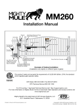
DRILL CLEARANCE HOLE
FOR
1/2" BOLT
DRILL CLEARANCE HOLE
FOR
1/2" BOLT
MOUNTING TEMPLATE
CABLE GATE
LOCK
This convenient battery powered wireless lock has many uses, including; multiple user
access to property, securing items such as boats or trailers and anything else secured
with a chain or cable.
Items Required - not included:
1. (8) AA Batteries*
2. (2) 3/8” carriage bolts, (2) 3/8” nuts and (2) 3/8”
washers (bolts must be at 1” longer than thickness
of gate post you are mounting to)
3. Other hardware may be needed depending on type
of cable, rope or chain being used. See EXAMPLES
on page 6.
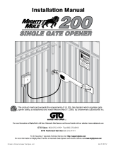
Kit Includes:
A. Lock (1)
B. Keys (2)
C. Cable/Chain Ring (1)
D. Mounting Template (1)
E. Remote Transmitter (1)
Gate Chain Lock
Driveway Cable Lock
To use as a lock for gate chain,
mount lock on outside face of non-
hinge post as illustrated.
To use as a lock for driveway
cable, mount lock on post facing
other driveway post as illustrated.

2 Cable/Gate Lock Instruction Manual • REV 10.29.13
STEP 1: Remove Lock Housing
Place key in lock and turn clockwise disengaging cable hook.
Remove cover fastener.
Remove cover.
1
2
3

Cable/Gate Lock Instruction Manual • REV 10.29.13 3
STEP 2: Attach Lock to Post
Affix included mounting template to post, and drill 3/8” holes through post.
Use 3/8” carriage bolts, washers, and nuts to fasten as shown.
1
2
Bolt must penetrate post
with a maximum of 1” extra
for securing washer and nut
Gate Lock Option
mounts on outside of
non-hinged gate post
Cable Lock Option
mounts on side of post
facing other drive post

4 Cable/Gate Lock Instruction Manual • REV 10.29.13
STEP 4: Setting Your Personal Code
STEP 3: Install 8 AA Lithium Batteries
1
1
2
3
All GTO transmitters are set to a standard settings and are ready to operate lock. For your safety and
security, we strongly recommend replacing the factory setting with your own.
If you have additional transmitters, set all with
the same setting (DIP switch settings).
Remove back cover of transmitter.
Clip can be removed and oriented
in either direction.
Install the 8 AA batteries based on your application.
See chart below.*
Replace cover and clip (if re-
moved).
Use small screwdriver to move DIP
switches to random positions, but
not all in same position.
DIP Switches
* AA Battery Operating Temperature (Energizer™):
Alkaline: 0°F to 130°F
Lithium: -40°F to 140°F
+
0
ECE
1 2 3 4 5 6 7 8
+
0
ECE
1 2 3 4 5 6 7 8
+
0
ECE
1 2 3 4 5 6 7 8
+
0
ECE
1 2 3 4 5 6 7 8
1 2 3 4 5 6 7 8
LED Flash Light
Battery
DIP Switches
+
0
ECE
1 2 3 4 5 6 7 8
+
0
ECE
1 2 3 4 5 6 7 8

Cable/Gate Lock Instruction Manual • REV 10.29.13 5
LEARN
REMOTE
SOLAR
BAT T
+–
LEARN
REMOTE
STEP 5: Learning the Transmitter
Press and hold “LEARN REMOTE” button on
control board and the transmitter button at the
same time until you hear beep, then release.
Your personal transmitter
setting is now programmed.
Test lock. Secure cable hook, press
and hold transmitter button to ensure
the cable hook releases.
1
1
2
3
STEP 6: Re-attach the Lock Housing
Replace lock housing and secure with housing screw.

6 Cable/Gate Lock Instruction Manual • REV 10.29.13
STEP 7: Attaching Lock Ring Examples
Attach cable or rope to ring (included)
using optional hardware (not supplied).
Attach chain to ring (included) using
optional hardware (not supplied).
Place cable ring into lock hook and press
hook upward until it locks into place.
1
2
3
If using an existing cable, verify you have enough slack in cable to attach ring using directions below.
Leave approximately 6 inches of slack for every 10 feet of cable..
If using new cable, attach ring to one end and attach other end to second post with secure mounting
hardware, leaving approximately 6 inches of slack for every 10 feet of cable.
Thimble
Ring
(included)
Clip
Ring (included)
Quick Link
Possible Hardware Options
Mending Link Connecting Link
Quick Link
Shackle
Possible Hardware Options
Thimble Chain-Rope Clip

Cable/Gate Lock Instruction Manual • REV 10.29.13 7
Optional Accessories
Care and Maintenance
1 2 3
4 5 6
7 8
0
9
1 2 3
4 5 6
7 8
0
9
Gate Chain Lock
Optional
Wireless Keypad
1
2
ABC
3
DEF
4
GHI
5
JKL
6
MNO
7
PRS
8
TUV
9
WXY
0
STATUS
PROGRAM
CALLING
GRANTED
Optional wireless digital keypad (FM137) allows a four digit combination code
for family, friends, other guest and caretakers – without the need for multiple
transmitters. Program up to 25 different changeable codes and cancel as
needed.
Additional transmitter (FM135) for family and friends.
1. Periodically lubricate the illustrated points with silicon to keep the lock working smoothly.
2. Check and replace batteries if lock fails to disengage.
IMPORTANT:
Take special care to avoid
getting lubricant on
electrical components.
Lubricate these points
periodically to keep lock
working smoothly.

FCC WARNING: Changes or modifications to this unit not expressly approved by the party responsible for compliance
could void the user’s authority to operate the equipment. In accordance with FCC Part 15, Section 15.21, the manufacturer
is not responsible for any radio or TV interference caused by unauthorized modifications to this equipment. Such
modifications could VOID the user authority to operate the equipment.
NOTE: This equipment has been tested and found to comply with the limits for a Class B digital device, pursuant to
Part 15 of the FCC Rules. These limits are designed to provide reasonable protection against harmful interference in a
residential installation. This equipment generates, uses and can radiate radio frequency energy and, if not installed and
used in accordance with the instructions, may cause harmful interference to radio communications.
However, there is no guarantee that interference will not occur in particular installations. If this equipment does cause
harmful interference to radio or television reception, which can be determined by turning the equipment off and on, the
user is encouraged to try to correct the interference by one or more of the following measures: • Reorient or replace the
receiver antenna. • Increase the separation between the equipment and the receiver. • Connect the equipment into an outlet
on a circuit different from that which the receiver is connected. • Consult the dealer or an experienced radio/TV technician
for help.
GTO Limited One Year Warranty
Gates That Open, LLC gate openers and accessories are covered under warranty by the manufacturer against defects in materials
and manufacturer workmanship for a period of one (1) year from date of purchase, provided the recommended installation
procedures have been followed.
In the case of product failure due to defective material or manufacturer workmanship within the one (1) year warranty period, the
product will be repaired or replaced (at the manufacturer’s option) at no charge to the customer, if returned freight prepaid to GTO,
3121 Hartsfield Road, Tallahassee, Florida, USA 32303. IMPORTANT: Call (800) 543-1236 for a Return Goods Authorization
(RGA) number before returning accessory to factory. Products received at the factory without an RGA number will not be
accepted. Replacement or repaired parts are covered by this warranty for the remainder of the one (1) year warranty period or six
(6) months, whichever is greater. GTO will pay the shipping charges (equal to United Parcel Service GROUND rate) for return to the
owner of items repaired under warranty.
The manufacturer will not be responsible for any charges or damages incurred in the removal of the defective parts for repair, or for
the re-installation of those parts after repair. This warranty shall be considered void if damage to the product(s) was due to improper
installation or use, connection to an improper power source, or if damage was caused by electrical power surge, lightning, wind, fire,
flood, insects or other natural agent.
After the one (1) year warranty period, GTO, will make any necessary repairs for a nominal fee. Call GTO at (800) 543-1236 for more
information. This warranty gives you specific legal rights, and you may also have other rights which may vary from state to state.
This warranty is in lieu of all other warranties, expressed or implied. NOTE: Verification of the warranty period requires copies of
receipts or other proof of purchase. Please retain these records.
Gates That Open, LLC • 3121 Hartsfield Road • Tallahassee, Florida 32303
www.mightymule.com • 1-800-543-4283
Technical Support Hours: MON - FRI 8:00AM - 7:00PM (ET) • 1-800-543-1236
ACCESS CONTROLS
/