Page is loading ...

Cover photo may show optional equipment
not supplied with standard unit.
© Copyright 2007 Printed
Read the Operator’s manual entirely. When
you see this symbol, the subsequent
instructions andwarnings are serious - follow
without exception. Your life and the lives of
others depend on it!
!
Table of Contents
753124
RBT55120
Rear Blades
301-172M
Operator’s Manual
5/21/07

Table of Contents
RBT55120 Rear Blades 301-172M
5/21/07
Land Pride
Table of Contents
© Copyright 2007 All rights Reserved
Land Pride provides this publication “as is” without warrantyof any kind, eitherexpressedor implied.While every precautionhas beentaken in the preparation ofthis manual, Land
Pride assumesnoresponsibilityfor errorsoromissions.Neitheris anyliabilityassumed fordamagesresultingfromthe use oftheinformation containedherein. Land Pride reserves
the rightto reviseandimprove itsproductsas it seesfit.This publicationdescribes thestateof this productatthe time ofitspublication,andmay notreflect the productinthefuture.
Land Pride is aregistered trademark.
All other brands and product names are trademarks or registered trademarks oftheir respective holders.
Printed in the United States of America.
Important Safety Information . . . . . . . . . . .1
Safety at All Times . . . . . . . . . . . . . . . . . . . . . . . . . 1
Look For The Safety Alert Symbol . . . . . . . . . . . . .1
Safety Labels . . . . . . . . . . . . . . . . . . . . . . . . . . . . . 4
Introduction . . . . . . . . . . . . . . . . . . . . . . . .6
Application . . . . . . . . . . . . . . . . . . . . . . . . . . . . . . . 6
Using This Manual . . . . . . . . . . . . . . . . . . . . . . . . . 6
Owner Assistance . . . . . . . . . . . . . . . . . . . . . . . . . 6
Section 1: Assembly & Set-Up . . . . . . . . . .7
Tractor Requirements . . . . . . . . . . . . . . . . . . . . . .7
Weight & Horsepower . . . . . . . . . . . . . . . . . . . . 7
3-Point Hitch Assembly . . . . . . . . . . . . . . . . . . . 7
Hydraulic Outlets . . . . . . . . . . . . . . . . . . . . . . . .7
Hitch, Frame & Blade . . . . . . . . . . . . . . . . . . . . . . . 8
Tractor Hook-Up . . . . . . . . . . . . . . . . . . . . . . . . . . 9
Section 2: Options, Assembly & Set-Up .10
Blade Offset Cylinder . . . . . . . . . . . . . . . . . . . . . . 10
Blade Angling Cylinder . . . . . . . . . . . . . . . . . . . . 10
Blade Tilting Cylinder . . . . . . . . . . . . . . . . . . . . . . 11
Manual Offset, Angling and Tilting . . . . . . . . . . . .12
Manual Blade Angling . . . . . . . . . . . . . . . . . . . . . 12
Manual Blade Offset . . . . . . . . . . . . . . . . . . . . . . 12
Manual Blade Tilting . . . . . . . . . . . . . . . . . . . . . . 12
Gauge Wheel . . . . . . . . . . . . . . . . . . . . . . . . . . . . 13
Ratchet Jack Option . . . . . . . . . . . . . . . . . . . . 13
Hydraulic Cylinder Option . . . . . . . . . . . . . . . .13
Hydraulic Selector Valve . . . . . . . . . . . . . . . . . . . 14
Skid Shoe . . . . . . . . . . . . . . . . . . . . . . . . . . . . . . 15
End Plates . . . . . . . . . . . . . . . . . . . . . . . . . . . . . . 15
Wear Plates . . . . . . . . . . . . . . . . . . . . . . . . . . . . . 15
Section 3: Adjustments . . . . . . . . . . . . . .16
Blade Pitch . . . . . . . . . . . . . . . . . . . . . . . . . . . . .16
Blade Offset . . . . . . . . . . . . . . . . . . . . . . . . . . . . . 16
Manual Offset Adjustment . . . . . . . . . . . . . . . . 16
Hydraulic Offset Adjustment . . . . . . . . . . . . . . 16
Blade Angle and Reversing . . . . . . . . . . . . . . . . .16
Manual Angle Adjustment . . . . . . . . . . . . . . . . 16
Hydraulic Angle Adjustment . . . . . . . . . . . . . .16
Blade Tilt . . . . . . . . . . . . . . . . . . . . . . . . . . . . . . . 16
Manual Tilt Adjustment . . . . . . . . . . . . . . . . . .16
Hydraulic Tilt Adjustment . . . . . . . . . . . . . . . .16
Gauge Wheel . . . . . . . . . . . . . . . . . . . . . . . . . . . .17
Manual Gauge Wheel Adjustment . . . . . . . . . .17
Hydraulic Gauge Wheel Adjustment . . . . . . . .17
Section 4: Operating Procedures . . . . . .18
Operating Check List . . . . . . . . . . . . . . . . . . . . . .18
Transporting . . . . . . . . . . . . . . . . . . . . . . . . . . . . .18
Basic Operating Instructions . . . . . . . . . . . . . . . .18
General Operating Instructions . . . . . . . . . . . . . .19
Section 5: Maintenance & Lubrication . .20
Maintenance . . . . . . . . . . . . . . . . . . . . . . . . . . . .20
Lubrication . . . . . . . . . . . . . . . . . . . . . . . . . . . . . .20
Blade Pivot Shaft . . . . . . . . . . . . . . . . . . . . . . .20
Blade Tilt Shaft . . . . . . . . . . . . . . . . . . . . . . . .20
Front Pivot Shaft . . . . . . . . . . . . . . . . . . . . . . .21
Moldboard and Blade . . . . . . . . . . . . . . . . . . .21
Ratchet Jack . . . . . . . . . . . . . . . . . . . . . . . . . .21
Gauge Wheel Front Pivot . . . . . . . . . . . . . . . .22
Gauge Wheel Caster Tube . . . . . . . . . . . . . . .22
Gauge Wheel Hub . . . . . . . . . . . . . . . . . . . . . .22
Section 6: Specifications & Capacities . .23
Section 7: Features & Benefits . . . . . . . .24
Section 8: Appendix . . . . . . . . . . . . . . . . .25
Torque Values Chart . . . . . . . . . . . . . . . . . . . . . .25
Notes . . . . . . . . . . . . . . . . . . . . . . . . . . . . . . . . . .26
Warranty . . . . . . . . . . . . . . . . . . . . . . . . . . . . . . .27

1
Important Safety Information
5/21/07
RBT55120 Rear Blades 301-172M
Land Pride
Table of Contents
Important Safety Information
▲
Safety at All Times
Thoroughly read and understand
the instructions given in this
manual before operation. Refer to
the “Safety Label” section, read
all instructions noted on them.
Do not allow anyone to operate
this equipment who has not fully
read and comprehended this
manual and who has not been
properly trained in the safe
operation of the equipment.
▲ Operator should be familiar with
all functions of the unit.
▲ Operate implement from the
driver’s seat only.
▲ Do not leave tractor or implement
unattended with engine running.
▲ Dismounting from a moving
tractor could cause serious injury
or death.
▲ Do not stand between the tractor
and implement during hitching.
▲ Keep hands, feet, and clothing
away from power-driven parts.
▲ Wear snug fitting clothing to avoid
entanglement with moving parts.
▲ Watch out for wires, trees, etc.,
when raising implement. Make
sure all persons are clear of
working area.
▲ Turning tractor too tight may
cause implement to ride up on
wheels. This could result in injury
or equipment damage.
!
Look For The Safety Alert Symbol
The SAFETY ALERT SYMBOL indicates there is a
potential hazard to personal safety involved and extra
safety precaution must be taken. When you see this
symbol, be alert and carefully read the message that
follows it. In addition to design and configuration of
equipment, hazard control and accident prevention
are dependent upon the awareness, concern,
prudence and proper training of personnel involved in
the operation, transport, maintenance and storage of
equipment.
Be Aware of
Signal Words
A Signal word designates a degree or
level of hazard seriousness. The
signal words are:
Indicates an imminently hazardous
situation which, if not avoided, will
result in death or serious injury. This
signal word is limited to the most
extreme situations, typically for
machine components that, for
functional purposes, cannot be
guarded.
!
DANGER
Indicates a potentially hazardous
situation which, if not avoided, could
result in death or serious injury, and
includes hazards that are exposed
when guards areremoved. It may also
be used to alert against unsafe
practices.
Indicates a potentially hazardous
situation which, if not avoided, may
result in minor or moderate injury. It
may also be used to alert against
unsafe practices.
!
WARNING
!
CAUTION
For Your Protection
▲ Thoroughly read and understand
the “Safety Label” section, read all
instructions noted on them.
Shutdown and Storage
▲ Lower machine to ground, put
tractor in park, turn off engine, and
remove the key.
▲ Detach and store implements in a
area where children normally do
not play. Secure implement by
using blocks and supports.
OFF
REMO
VE
These are common practices that may or may not be applicable to the products described in
this manual.

2
Important Safety Information
RBT55120 Rear Blades 301-172M
5/21/07
Land Pride
Table of Contents
Transport
Machinery Safely
▲ Comply with state and local laws.
▲ Maximum transport speed for
implement is 20 mph. DO NOT
EXCEED. Never travel at a speed
which does not allow adequate
control of steering and stopping.
Some rough terrain require a
slower speed.
▲ Sudden braking can cause a
towed load to swerve and upset.
Reduce speed if towed load is not
equipped with brakes.
▲ Use the following maximum
speed - tow load weight ratios as
a guideline:
20 mph when weight is less
than or equal to the weight of
tractor.
10 mph when weight is double
the weight of tractor.
▲ IMPORTANT: Do not tow a load
that is more than double the
weight of tractor.
Use Safety
Lights and Devices
▲ Slow moving tractors, self-
propelled equipment, and towed
implements can create a hazard
when drivenonpublicroads.They
are difficult to see, especially at
night.
▲ Flashing warning lights and turn
signals are recommended
whenever driving on public roads.
Use lights and devices provided
with implement.
Practice Safe Maintenance
▲ Understand procedure before doing
work. Use proper tools and
equipment, refer to Operator’s
Manual for additional information.
▲ Work in a clean dry area.
▲ Lower the implement to the ground,
put tractor in park, turn off engine,
and remove key before performing
maintenance.
▲ Allow implement to cool completely.
▲ Do not grease or oil implement while
it is in operation.
▲ Inspect all parts. Make sure parts
are in good condition & installed
properly.
▲ Remove buildup of grease, oil or
debris.
▲ Remove all tools and unused
parts from implement before
operation.
Use A Safety Chain
▲ A safety chain will help control
drawn machinery should it
separate from the tractor
drawbar.
▲ Use a chain with the strength
rating equal to or greater than
the gross weight of the towed
machinery.
▲ Attach the chain to the tractor
drawbar support or other
specified anchor location. Allow
only enough slackin the chain to
permit turning.
▲ Do not use safety chain for
towing.
These are common practices that may or may not be applicable to the products described in
this manual.

3
Important Safety Information
5/21/07
RBT55120 Rear Blades 301-172M
Land Pride
Table of Contents
Prepare for Emergencies
▲ Be prepared if a fire starts.
▲ Keep a first aid kit and fire
extinguisher handy.
▲ Keep emergency numbers for
doctor, ambulance, hospital and
fire department near phone.
911
Wear
Protective Equipment
▲ Protectiveclothing and equipment
should be worn.
▲ Wear clothing and equipment
appropriate for the job. Avoid
loose fitting clothing.
▲ Prolonged exposure to loud noise
can cause hearing impairment or
hearing loss. Wear suitable
hearing protection such as
earmuffs or earplugs.
▲ Operating equipment safely
requires the full attention of the
operator. Avoid wearing radio
headphones while operating
machinery.
Avoid High
Pressure Fluids Hazard
▲ Escaping fluid underpressurecan
penetratetheskincausingserious
injury.
▲ Avoid the hazard by relieving
pressure before disconnecting
hydraulic lines.
▲ Use a piece of paper or
cardboard, NOT BODY PARTS, to
check for suspected leaks.
▲ Wear protective gloves and safety
glasses or goggles when working
with hydraulic systems.
▲ If an accident occurs, see a
doctor immediately. Any fluid
injected into the skin must be
treated within a few hours or
gangrene may result.
Keep Riders
Off Machinery
▲ Riders obstruct the operator’s
view, they could be struck by
foreign objects or thrown from the
machine.
▲ Never allow children to operate
equipment.
These are common practices that may or may not be applicable to the products described in
this manual.

4
Important Safety Information
RBT55120 Rear Blades 301-172M
5/21/07
Land Pride
Table of Contents
818-339C
Warning: High Pressure
818-487C
Danger Avoid Injury
17837
17837
Safety Labels
Your 3-Way Rear Blade comes equipped with all safety labels
in place. They were designed to help you safely operate your
implement. Read and follow their directions.
1. Keep all safety labels clean and legible.
2. Replace all damaged or missing labels. To order new
labels go to your nearest Land Pride dealer or visit our
dealer locator at landpride.com.
3. Some new equipment installed during repair requires
safety labels to be affixed to the replaced component as
specified by Land Pride. When ordering new components
make sure the correct safety labels are included in the
request.
4. Refer to this section for proper label placement.
To install new labels:
a. Clean the area the label is to be placed.
b. Spray soapy water on the surface where the label is to
be placed.
c. Peel backing from label. Press firmly onto the surface.
d. Squeeze out air bubbles with the edge of a credit card.


6
Introduction
RBT55120 Rear Blades 301-172M
5/21/07
Land Pride
Table of Contents
Introduction
If customer service or repair parts are required contact a
LandPridedealer. Adealerhas trainedpersonnel,repair
parts and equipment needed to service the Rear Blade.
Thepartsonyour3-WayRear Bladehavebeenspecially
designedandshouldonlybereplacedwithgenuineLand
Pride parts. Therefore, should your Rear Blade require
replacement parts go to your Land Pride Dealer.
Serial Number Plate
For prompt service always use the serial number and
modelnumber when ordering partsfrom your Land Pride
dealer.Besuretoincludeyourserialandmodel numbers
incorrespondencealso.Referto Figure1 forthe location
of your serial number plate.
Serial Number Plate Location
Figure 1
Further Assistance
Your dealer wants you to be satisfied with your new 3-
WayRear Blade. Iffor anyreason you donot understand
any part of this manual or are not satisfied with the
service received, the following actions are suggested:
1. Discuss the matter with your dealership service
manager making sure he is aware of any problems
youmay have and that he has had the opportunity to
assist you.
2. If you are still not satisfied, seek out the owner or
general manager of the dealership, explain the
problem and request assistance.
3. For further assistance write to:
Land Pride Service Department
1525 East North Street
P.O. Box 5060
Salina, Ks. 67402-5060
E-mail address
lpser[email protected]
17837
Land Pride welcomes you to the growing family of new
product owners.
This3-WayRear Bladehas beendesigned withcareand
built by skilled workers using quality materials. Proper
assembly,maintenanceand safeoperatingpractices will
help you get years of satisfactory use from the machine.
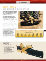
Application
LandPride’sRBT55120Series3-WayRearBladeisbuilt
tough from the ground up for applications ranging from
landscaping, construction, snow removal, feedlot
cleaning and all-around farm use. By using hydraulics at
all three positions, time can be utilized efficiently by
making changes on the go. Available options include
single or double hydraulic gauge wheels, side plates for
holding dirt in and skid shoes for blade protection.
See “Section 6: Specifications & Capacities” on page
23 and “Section 7: Features & Benefits” on page 24 for
additional information and performance enhancing
options.
Using This Manual
•
This Operator’s Manual is designed to help familiarize
you with safety, assembly, operation, adjustments,
troubleshooting, and maintenance. Read this manual
and follow the recommendations to help ensure safe
and efficient operation.
• The information contained within this manual was
current at the time of printing. Some parts may change
slightly to assure you of the best performance.
• To order a new Operator’s or Parts Manual contact
your authorized dealer. Manuals can also be
downloaded, free-of-charge from our website at
www.landpride.com or printed from the Land Pride
Service & Support Center by your dealer.
Terminology
“Right” or “Left” as used in this manual is determined by
facing forward in the direction the machine will operate
while in use unless otherwise stated.
Definitions
Owner Assistance
The Warranty Registration card should be filled out by
the dealer at the time of purchase. This information is
necessary to provide you with quality customer service.
NOTE: A special point of information that the
operator must be aware of before continuing.
IMPORTANT: A special point of information related
to its preceding topic. Land Pride’s intention is that
this information should be read and noted before
continuing.

7
Section 1: Assembly & Set-Up
5/21/07
RBT55120 Rear Blades 301-172M
Land Pride
Table of Contents
Tractor Requirements
Weight & Horsepower
Tractor rating should be between 90 - 180 horsepower.
Tractors outside this range must not be used.
3-Point Hitch Assembly
A 3-Point Category ll or lII hitch is required. The lower
3-Point arms of the 3-Point hitch must be stabilized to
preventside-to-sidemovement.Mosttractorshavesway
blocks or adjustable chains for this purpose.
Hydraulic Outlets
The number of required hydraulic duplex outlets at the
tractor is dependent upon how the 3-Way Rear Blade is
set-up.
• Nooutletsarerequiredifthe3-WayRearBladeisset-up
with manual links and ratchet jacks only.
• One to three duplex outlets are required if the 3-Way
Rear Blade is set-up with any one or more of the
following hydraulic cylinders; Offset Cylinder, Tilt
CylinderandAngleCylinder.Eachcylinderwillrequirea
duplex outlet at the tractor.
• A fourth duplex outlet is required if a gauge wheel is
purchased with a hydraulic cylinder.
A Selector Valve Kit may be purchased through your
local Land Pride dealer if your tractor does not have the
required number of duplex outlets. This kit provides a
way to operate 2 cylinders with one outlet, thereby
reducing the number of outlets at the tractor by one.
NOTE: Ballast may need to be added to your tractor
to maintain steering control. Refer to your tractor’s
operator manual to determine if additional ballast is
needed.
Land Pride Selector Valve Kit
Part No. Part Description
300-154A DOUBLE SELECTOR VALVE ASSY
For use with two duplex outlets. Will allow
operation of 3 cylinders with 2 tractor outlets.
Section 1: Assembly & Set-Up

8
Section 1: Assembly & Set-Up
RBT55120 Rear Blades 301-172M
5/21/07
Land Pride
Table of Contents
Hitch, Frame & Blade
1. Locate shipping crate on a level surface. Remove &
separate blade assemblies from shipping crate.
Refer to Figure 1-1:
2. Use a lifting device to set blade pivot assembly (#9)
upright.Removebolts(#6),lockwashers(#7)&pivot
cap (#8) from blade pivot assembly (#9). Do not
remove shipping block in the blade tilt housing.
3. Carefully insert blade pivot assembly (#9) into main
frame (#2) at a 90˚ angle to the frame.
4. Reinstall pivot cap (#8), lockwashers (#7) and
3/4"-16 x 1 3/4" GR5 hex head cap screws (#6).
Tighten hardware to secure main frame to blade
pivot assembly.
5. Remove 3/4" x 4 3/8" hitch pin (#10) and rotate jack
stand (#11) to a vertical position. Re-insert pin (#10)
and secure with lock pin.
6. Lower unit to ground and unhook lifting device.
7. Remove front pivot shaft (#3) from front hitch
assembly (#1) by removing 1/2" bolts (#5) and lock
washer (#4).
8. Secure front hitch assembly (#1) to a lifting deviceor
attach to a tractor. See “Tractor Hook-Up” on page 9.
IMPORTANT: Do not remove shipping block from
thebladetilthousing untilall cylindersand/or ratchet
jack and manual links have been installed.
9. Insert main frame(#2) into front hitch (#1) as shown.
Reinstall front pivot shaft (#3) and secure with 1/2”
lock washer(#4), 1/2"-13 x 1 1/2” GR5 bolts (#5).
Tighten hardware to secure front pivot shaft (#3).
10. If not already done, attach unit to tractor
3-point hitch. The top 3-point hitch pin and linch pin
are to be supplied by the customer. See Figure 1-3
on page 9 for category settings.
11. Re-check all hardware for tightness. Torque all bolts
to specifications as listed in the “Torque Values
Chart” on page 11.
!
CAUTION!
Always check all hardware for tightness before using the
blade. The moldboard will fall off if 3/4" bolts (#6) and/or
1/2" bolts (#12) are missing
Rear Blade Assembly
Figure 1-1
12888
SHIPPING BLOCK
DO NOT REMOVE UNTIL AFTER ALL
HYDRAULIC CYLINDERS AND/OR
RATCHET JACK AND MANUAL LINKS
HAVE BEEN INSTALLED.

9
Section 1: Assembly & Set-Up
5/21/07
RBT55120 Rear Blades 301-172M
Land Pride
Table of Contents
Tractor Hook-Up
Refer to Figure 1-2 & Figure 1-3:
!
DANGER!
Tractor hook-up to equipment is dangerous and can result in
serious injury or death. Do not allow anyone to stand between
the blade and tractor during hook-up operations. Do not
operate the hydraulic 3-point lift controls while someone is
directly behind the tractor or near the blade.
1. Slowlybacktractorupto the 3-WayRear Bladewhile
using the tractor’s 3-point hydraulic control to align
thelowerhitch link holeswith lowerhitch clevis holes
on the Rear Blade.
2. Engage tractor park brake, shut tractor engine off
and remove key before dismounting from tractor.
3. With tractor’s lower hitch arms aligned and
positioned in the clevises, insert hitch pins through
the clevis lugs and lower arm holes. Be sure to use
the bushings as shown in Figure 1-3. Secure hitch
pins with linch pins.
4. Connect top center link to the upper pivot hitch
mounting holes using customer supplied clevis pin
and linch pin.
5. Ensure that the lower hitch arms are blocked to
prevent excessive side movement.
6. Remove hitch pin and raise support stand fully up.
Reinsert hitch pin and secure with lock pin.
7. Return to the tractor and slowly operate controls up
and down to check for clearance. Make certain the
Rear Blade does not interfere with the tractor hitch,
tires, and drawbar. Move or remove the drawbar if it
interferes.
8. Manually adjust one of the two lower lift arms up or
down to level the Rear Blade from left to right.
9. Manually adjust length of the top-link to level the
Rear Blade from front to rear.
Tractor 3-Point Hitch
Figure 1-2
23998
Lower 3-Point Hitch Setting
Figure 1-3
12864
Category ll
Standard & Quick Hitch
Category ll
Standard Hitch
Category lll
Standard & Quick Hitch

10
Section 2: Options, Assembly & Set-Up
RBT55120 Rear Blades 301-172M
5/21/07
Land Pride
Table of Contents
Section 2: Options, Assembly & Set-Up
Blade Offset Cylinder
Refer to Figure 2-1:
Assemble the hydraulic hoses to the hydraulic cylinder
before placing the cylinder on the blade.
1. Position hydraulic cylinder (#3) with ports on top as
shown. Install two straight fittings (#4) into the
cylinder ports as shown. Tighten as needed.
2. Screw 116" long hydraulic hoses (#5) into
straight fittings (#4) and tighten.
3. Thread adapter fittings (#6) to the other end of the
hydraulichosesandtighten.(Hydrauliccouplingsnot
furnished.)
4. Attach hydraulic cylinder to the lugs located on the
left side of the 3-Way Rear Blade with clevis pins
(#2).Makesurehydraulicportsare positionedon top
and the cylinder base in positioned to the front as
shown.
5. Secure clevis pins with hair pin cotters (#1).
6. Route hoses through hose bracket located on the
right side of the front hitch. Connect hoses to
tractor's hydraulic system.
Hydraulic Blade Offsetting
Figure 2-1
IMPORTANT: Do not remove shipping block from
thebladetilthousing untilall cylindersand/or ratchet
jack and manual links have been installed.
IMPORTANT: Attach cylinder base to the front hitch
lug. The cylinder base will interfere with the main
frame if attached to the rear lug.
25502
Blade Angling Cylinder
Refer to Figure 2-2:
1. Position hydraulic cylinder (#3) with ports on top as
shown. Install two straight fittings (#4) into the
cylinder ports as shown. Tighten as needed.
2. Screw 116" long hydraulic hoses (#5) into
straight fittings (#4) and tighten.
3. Thread adapter fittings (#6) to the other end of the
hydraulichosesandtighten.(Hydrauliccouplingsnot
furnished.)
4. Attach hydraulic cylinder to the lugs on the right side
of the frame with clevis pins (#1). Make sure
hydraulicportsarepositioned ontopandthecylinder
base in positioned to the front as shown.
5. Secure clevis pins with hair pin cotters (#2).
6. Route hoses through hose bracket located on the
right side of the front hitch. Connect hoses to
tractor's hydraulic system.
Hydraulic Blade Angling
Figure 2-2
IMPORTANT: Do not remove shipping block from
thebladetilthousing untilall cylindersand/or ratchet
jack and manual links have been installed.
IMPORTANT: Attach cylinder base to the front hitch
lug. If attached to the rear lug, the base will interfere
with the main frame.
25503

11
Section 2: Options, Assembly & Set-Up
5/21/07
RBT55120 Rear Blades 301-172M
Land Pride
Table of Contents
Blade Tilting Cylinder
Refer to Figure 2-3:
1. Install two 90 degree elbows (#4) into the hydraulic
cylinder ports (#3) as shown. Tighten as needed.
IMPORTANT: Do not remove shipping block from
thebladetilthousing untilall cylindersand/or ratchet
jack and manual links have been installed.
IMPORTANT: Assemble base end of cylinder to the
lug located on the blade pivot as shown.
2. Screw 140" long hydraulic hoses (#5) into
elbows (#4) and tighten.
3. Thread adapter fittings (#6) to the other end of the
hydraulichosesandtighten.(Hydrauliccouplingsnot
furnished.)
4. Attach hydraulic cylinder (#3) to the lugs at the back
of the blade with clevis pins (#2). Make sure
hydraulic ports are positioned on the back and the
cylinder base is mounted to the center lug as shown.
5. Secure clevis pins with hair pin cotters (#1).
6. Remove shipping block at this time.
Hydraulic Blade Tilting
Figure 2-3
SHIPPING BLOCK
DO NOT REMOVE UNTIL AFTER ALL
HYDRAULIC CYLINDERS AND/OR
RATCHET JACK AND MANUAL LINKS
HAVE BEEN INSTALLED.
25504

12
Section 2: Options, Assembly & Set-Up
RBT55120 Rear Blades 301-172M
5/21/07
Land Pride
Table of Contents
Manual Offset, Angling and Tilting
The manual links and ratchet jack may be used in place
of the hydraulic cylinders.
Manual Blade Angling
Refer to Figure 2-4:
7. Attach blade angling links (#3 and #4) to the right
side of the Rear Blade as shown with two 1" clevis
pins (#1). Secure with hair pin cotters (#5).
8. Adjust blade angle by removing hitch pin (#2) and
moving outer link (#3) to a different hole. Replace
hitch pin and secure with hair pin cotter (#5).
IMPORTANT: Do not remove shipping block from
thebladetilthousing untilall cylindersand/or ratchet
jack and manual links have been installed.
Manual Offset, Angling and Tilting
Figure 2-4
SHIPPING BLOCK
DO NOT REMOVE UNTIL AFTER ALL
HYDRAULIC CYLINDERS AND/OR
RATCHET JACK AND MANUAL LINKS
HAVE BEEN INSTALLED.
Blade Angling
Blade Offset
Blade Tilting
25508
Manual Blade Offset
Refer to Figure 2-4:
9. Attach blade offset links (#3 and #4) to the left side
of the Rear Blade as shown with two 1" clevis
pins (#1). Secure with hair pin cotters (#5).
10. Adjust offset angle by removing hitch pin (#2) and
moving outer link (#3) to a different hole. Replace
hitch pin and secure with hair pin cotter (#5).
Manual Blade Tilting
Refer to Figure 2-4:
1. Attach ratchet jack (#6) to the back side of the Rear
Blade as shown with two 1" clevis pins (#1). Secure
with hair pin cotters (#5).
2. Adjust blade tilt by setting the lock on the ratchet
lever and pumping the lever back and forth to raise
one end of the blade higher than the other end.
Reposition ratchet lock and pump lever back and
forth to tilt blade in the opposite direction.
3. Remove shipping block after ratchet jack (#6) has
been installed.

13
Section 2: Options, Assembly & Set-Up
5/21/07
RBT55120 Rear Blades 301-172M
Land Pride
Table of Contents
Ratchet Jack Option
1. Attach ratchet jack(#19) to the mounting lugs on the
gauge wheel arm (#3) and mounting bracket (#11)
with two 1" clevis pins (#20). Secure pins with hair
pin cotters (#21).
Hydraulic Cylinder Option
1. Position hydraulic cylinder (#15) with ports on top as
shown. Thread 90 degree elbows (#13) into the two
ports and tighten.
2. Screw123" long hydraulic hoses (#14) to the elbows
and tighten.
3. Thread hydraulic couplings (#18) (couplings
provided by customer) to the other end of hydraulic
hoses and tighten.
4. Attach hydraulic cylinder to the lugs on the gauge
wheel with two 1" clevis pins (#17). Make sure
hydraulic ports are positioned on top and cylinder
base is located to the front as shown.
5. Secure clevis pins with hair pin cotters (#16).
6. Route the hoses through the hose brackets located
onthetopofthemainframeandrightside ofthefront
hitch. Connect hoses to tractor's hydraulic system.
IMPORTANT: Assemble base end of cylinder to the
front lug on the mounting bracket (#11) as shown.
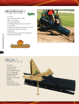
Gauge Wheel
Kit Bundles
301-149A HYDRAULIC SINGLE GAUGE WHEEL
301-150A HYDRAULIC DUAL GAUGE WHEEL
301-283A MANUAL SINGLE GAUGE WHEEL
301-248A MANUAL DUAL GAUGE WHEEL
Refer to Figure 2-5:
1. Attach gauge wheel mounting bracket (#11) to Rear
Bladeframewith two3/4”-10x101/2” GR5hexhead
bolts (#8). and 3/4” hex nuts (#10). Tighten nuts to
correct torque.
2. Insert gauge wheel hitch tube (#9) in gauge wheel
arm (#3).
3. Attach gauge wheel arm (#3) to mounting bracket
(#11) with 3/4”-10 x 10 1/2” GR5 hex head bolt (#8).
and 3/4” hex nut (#10). Tighten nut to correct torque.
4. Insert gauge wheel caster assembly (single wheel
caster #1) or (dual wheel caster #2) in gauge wheel
arm (#3) and retainer washer (#4). Secure caster
assembly with 1/2” x 2 1/2” long roll pin (#5).
5. Attach center floating link (#12) to the front hitch with
1 1/4” x 1 3/4” hitch pin (#7). Secure with hair pin
cotter (#6).
Gauge Wheel Assembly
Figure 2-5
25505

14
Section 2: Options, Assembly & Set-Up
RBT55120 Rear Blades 301-172M
5/21/07
Land Pride
Table of Contents
Hydraulic Selector Valve Assembly
Figure 2-6
25509
Hydraulic Selector Valve
Refer to Figure 2-6:
An optional hydraulic selector valve kit may be
purchased that bolts to the front hitch frame. This kit
provides a way to operate 2 cylinders with one outlet,
thereby reducing the number of outlets at the tractor by
one. See also “Tractor Requirements” on page 7.
Kit Bundle
300-154A Double Selector Valve Assembly
1. Attachdivertervalvestand(#16) to thehitch withtwo
1/2"-13 x 1 3/4" GR5 hex head cap screws (#17),
spring lock washers (#10) and hex nuts (#11).
Tighten nuts to the correct torque.
2. Attach adjustment tube (#13) to the stand with one
1/2"-13 x 3/4" GR5 hex head cap screws (#15).
Tighten bolt to the correct torque.
3. Attach extension arm (#14) to adjustment tube with
two 3/8”-16 x 3/4” GR5 hex head cap screws (#12).
Tighten bolts to the correct torque.
4. Attach valve base plate (#6) to extension arm (#14)
withtwo1/2”flatwashers(#9),lockwasher(#10)and
3/8”-13 hex nut (#11). Tighten nut to the correct
torque.
5. Attach double selector valve (#4) to valve base
plate (#6) with two 3/8"-16 x 3" GR5 hex head cap
screws (#5), spring lock washers (#7) and hex
nuts (#8). Tighten nuts to the correct torque.
6. Apply teflon tape to the pipe threads of six
3/4 x 1/2MNPT elbows (#1) and screw them into the
double selector valve (#4) as shown. Tighten to
correct orientation.
7. Attach blade offset hydraulic hoses (#18) to the right
side elbows.
8. Attach hydraulic hoses (#19) from one of the other
cylinders to the left elbows.
9. Attach tractor connected hydraulic hoses (#2) to the
top elbows.
10. Thread hydraulic adapters (#3) (couplings supplied
by customer) onto hydraulic hoses (#2) and tighten.

15
Section 2: Options, Assembly & Set-Up
5/21/07
RBT55120 Rear Blades 301-172M
Land Pride
Table of Contents
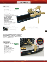
Skid Shoe
Refer to Figure 2-7:
The skid shoes are attached to both ends of the blade to
help prevent damage to the surface of the ground by the
blade.
Kit Bundle
301-110A SKID SHOE ASSEMBLY
1. Attachskidshoe mount (#4) with two 1/2"-13 x 41/2"
GR5 hex head cap screw (#1), flat washers (#8),
spring lock washers (#6) and hex nuts (#7). Tighten
hardware to the correct torque.
2. Insert skid shoe (#3) into skid shoe mount (#4).
Secure with clevis pin (#2) and hair pin cotter (#5).
3. Repeat steps 1 & 2 for the other side.
Skid Shoe Assembly
Figure 2-7
End Plates
Refer to Figure 2-8:
End plates are attached to both ends of the blade,
eliminating spillage whenmoving snow or loose material.
Kit Bundle
301-147A END PLATES
1. Attach right hand end plate (#3) to the moldboard as
shown with two 5/8"-11 x 2" GR5 hex head cap
screws (#4), spring lock washer (#7) and hex nuts
(#8). Draw hex nuts up snug. Do not tighten.
2. Attach side plate support strap (#2) with two 1/2”-13
x11/4”GR5 hexheadcap screws(#1),lockwashers
(#5) and hex nuts (#6). Draw hex nuts up snug. Do
not tighten.
12549
NOTE: Alternate tightening of bolts when installing
mounting hardware. Some deflection may occur in
moldboard.
3. First tighten hex nuts (#8) to the correct torque and
then next nuts (#6) last.
4. Repeat steps 1 and 3 for the left hand end plate.
.
End Plate Assembly
Figure 2-8
Wear Plates
Refer to Figure 2-9:
Hardened wear plates are attached to both ends of the
blade. These plates are designed to protect moldboard
edges when blade is used for digging ditches or working
abrasive material.
Kit Bundle
301-148A HARDENED WEAR PLATES (PAIR)
1. Attach wear plate (#2) to the moldboard with
5/8”-11 x 2” GR52 round head square neckbolt (#1),
lockwasher (#3) and hex nut (#4). Tighten hardware
to correct torque.
2. Repeat step 1 for the left hand wear plate.
Wear Plate Assembly
Figure 2-9
12550

16
Section 3: Adjustments
RBT55120 Rear Blades 301-172M
5/21/07
Land Pride
Table of Contents
Blade Pitch
Bladepitchcan beadjustedby lengtheningor shortening
the tractor’s top center 3-point link.
Blade Offset
Manual Offset Adjustment
Refer to Figure 2-4 on page 12:
The blade offset has 15 adjustments up to 33" left or
right. (Center position, 7 positions right and 7 positions
left.)
1. Manually adjust blade offset by removing hitch
pin (#2) and moving outer link (#3) to a differenthole
position.
2. Replace hitch pin and secure with hair pin
cotter (#5).
Hydraulic Offset Adjustment
!
CAUTION!
The blade may come in contact with the tractor rear tire when
offsetting blade to maximum position and angling blade in the
same direction to most severe angle.
Refer to Figure 2-1 on page 10:
The blade can be offset hydraulically by as much as 33"
to the right or left with the offset cylinder.
1. If the offset cylinder is attached to the selector valve,
make certain the valve lever is set to operate that
cylinder.
2. Operate tractor control lever to change blade offset
by as much as 33” right or left.
Blade Angle and Reversing
!
CAUTION!
Avoid injury from falling blade by always check to make sure
all hardware is secured properly before rotating blade.
Manual Angle Adjustment
Refer to Figure 2-4 on page 12:
There are 15 blade angle positions; up to 45 degrees
right or left. (Center, 7 clockwise and 7 counterclockwise
positions.)
1. Adjust blade angle by removing hitch pin (#2) and
moving outer link (#3) to a different hole position.
2. Replace hitch pin and secure with hair pin
cotter (#5).
IMPORTANT: Never fully extend hydraulic offset
cylinder or angle cylinder. Damage may occur.
3. The blade may also be rotated around 180 degrees.
a. Disconnect angling link from blade turntable lug.
b. Rotate Rear Blade clockwise 180 degrees.
c. Reconnect angling link to turntable lug.
Hydraulic Angle Adjustment
!
CAUTION!
The blade may come in contact with the tractor rear tire when
offsetting blade to maximum position and angling blade in the
same direction to most severe angle.
Refer to Figure 2-2 on page 10:
Adjust blade angle with angling cylinder by as much as
45 degrees clockwise and counterclockwise.
1. If the angling cylinder is attached to the selector
valve, make certain the valve lever is set to operate
that cylinder.
2. Operate tractor control lever to change blade angle
by as much as 45 degrees forward or backward.
3. The blade may also be rotated 180 degrees.
a. Disconnect angle cylinder from blade turntable
lug.
b. Rotate 3-Way Rear Blade clockwise 180 degrees.
c. Reconnect angle cylinder to turntable lug.
Blade Tilt
!
CAUTION!
Avoid injury from falling blade by always checking to make
sure all hardware is secured properly before tilting blade.
Manual Tilt Adjustment
Refer to Figure 2-4 on page 12:
The blade end can be tilted manually by as much 30
degrees with the ratchet jack.
1. Set ratchet lock and pump lever back and forth to
raise one end of the bladehigher than the other end.
2. Reposition ratchet lock and pump lever back and
forth to tilt blade in the opposite direction.
Hydraulic Tilt Adjustment
IMPORTANT: Make sure the angling link is properly
re-installed before using the blade.
IMPORTANT: Never fully extend hydraulic offset
cylinder or angle cylinder. Damage may occur.
IMPORTANT: Make sure the hydraulic cylinder is
properly re-installed before using the blade.
Section 3: Adjustments

17
Section 3: Adjustments
5/21/07
RBT55120 Rear Blades 301-172M
Land Pride
Table of Contents
Refer to Figure 2-3 on page 11:
The blade end can be tilted hydraulically with the tilt
cylinder by as much as 30 degrees.
1. If the tilting cylinder is attached to the selector valve,
make certain the valve lever is set to operate that
cylinder.
2. Operate tractor control lever to change blade tilt by
as much as 30 degrees.
Gauge Wheel
Refer to Figure 2-5 on page 13:
The gauge wheel provides accurate depth control when
grading, leveling or terracing. The height of the gauge
wheel is determined by adjusting the ratchet jack or
hydraulic cylinder.
Manual Gauge Wheel Adjustment
1. Set ratchet lock and pump lever back and forth to
raise the gauge wheel.
2. Reposition ratchet lock and pump lever back and
forth to lower gauge wheel.
Hydraulic Gauge Wheel Adjustment
1. Ifthegaugewheelcylinderisattachedtotheselector
valve, make certain the valve lever is set to operate
that cylinder.
2. Operate tractor control lever to change gauge wheel
height up or down.
IMPORTANT: The top center 3-point link can be
removed from both the blade and tractor before
using the gauge wheel accessory with the blade.

18
Section 4: Operating Procedures
RBT55120 Rear Blades 301-172M
5/21/07
Land Pride
Table of Contents
Section 4: Operating Procedures
Operating Check List
Hazard control and accident prevention are dependent
upon the awareness, concern, prudence and proper
training involved in the operation, transport,
maintenance and storage of the blade. Therefore, it is
absolutely essential that no one operates the 3-Way
Rear Blade without first having read, fully understood
and become totally familiar with the Operator’s Manual.
Make sure the operator has paid particular attention to:
• Important Safety Information, pages 1 to 5
• Section 1: Assembly & Set-Up, page 7
• Section 3: Adjustments, page 16
• Section 4: Operating Procedures, page 18
• Section 5: Maintenance & Lubrication, page 20
Makethe following inspections afterattaching the 3-Way
Rear Blade to the tractor:
1. Inspect tractor safety equipment to make sure it is in
good working condition.
2. Carefully raise and lower the implement to ensure
that the drawbar, tires, and other equipment on the
tractor do not contact the frame and moldboard.
3. Carefully pivot Rear Blade fully clockwise and offset
blade such that the moldboard end closest to the
tractor is in line with the tractor tire. Raise and lower
implement to ensure tractor tires and tractor do not
contact the blade.
4. Carefully pivot Rear Blade fully counterclockwise
andoffsetbladesuchthatthe moldboardendclosest
to the tractor is in line with the tractor tire. Raise and
lowerimplement toensuretractortires andtractordo
not contact the blade.
5. Inspect hydraulic hoses for wear, damage and
hydraulic leaks. See “Avoid High Pressure Fluids
Hazard”onpage 3.
Replacedamagedandwornhoses
with genuine Land Pride parts.
Transporting
!
CAUTION!
When traveling on public roads at night or during the day, use
accessory lights and devices for adequate warning to
operators of other vehicles. Comply with all federal, state and
local laws.
Operating Checklist
✔ Check Reference
Check 3-point Hook-up procedure. Be sure all
pins have been installed and are secured.
Page 9
All blade adjustments have been made and pins
have been installed and are secured.
Page 8
The operator has read and understood how to
operate the blade.
Page 18
The Rear Blade has been lubricated as required.
Page 20
Check the blade initially and periodically for loose
bolts & pins, See Torque Values Chart.
Page 25
1. Whentraveling onroadways,transportin such a way
that faster moving vehicles may pass you safely.
2. Leave enough clearance on both sides of the Rear
Bladewhentravelingstraightormakingturnstokeep
the blade from contacting obstacles such as
buildings, trees or fences.
3. Slow down when traveling over rough or hilly terrain.
Basic Operating Instructions
!
WARNING!
Do not use blade tilt to raise tractor tires off the ground for
repair. Improper use can damaged the 3-Way Rear Blade.
!
WARNING!
Do not operate the side shift cylinder with blade in the ground
or to push or pull other objects. Improper use can damaged
the 3-Way Rear Blade.
!
WARNING!
Do not use the Rear Blade for pulling fence posts, stumps, etc.,
lifting objects, carry objects or towing other equipment. Any
of the above can result in 3-Way Rear Blade damage, serious
bodily injury or death.
!
DANGER!
Never carry a person on the Rear Blade. A person can fall and
be ran over by the Rear Blade or tractor causing serious
injury or death.
1. Thoroughly inspect the work area for buried utility
cables, pipelines, sprinkler heads and any
unforeseen objects. Mark any potential hazards.
2. Placegradestakesif youintend todevelop aspecific
grade or soil level.
3. Adjust the blade to the desired angle, tilt, and offset
position before lowering the blade to the ground.
4. Lower blade to the ground and proceed forward at a
speed of no more than 2 to 4 mph. The blade should
immediately begin shaving the soil surface.
5. Set the tractor’s draft-link height control to the
desired position. With the blade set at a 90 degree
angleyoumayneedtoraise thebladeslightly so that
the dirt or gravel can flow out evenly under the blade
effectively shaving off high spots and filling in
potholes or depressions.
IMPORTANT: Avoid catching hydraulic hoses on
brush, post, stumps, and other protrusions that
could damage and/or break them.
/