Page is loading ...

Leader in Audio Engineering
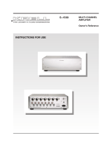
KAV-1500
Five-Channel Power Amplifier
Instructions for Use
Owner’s Reference

KAV-1500
Five-Channel Power Amplifier
Instructions for Use
v 00.0
Krell Industries, Inc.
45 Connair Road
Orange, CT 06477-3650 USA
TEL 203-799-9954
FAX 203-891-2028
E-MAIL [email protected]
WEBSITE http://www, krellonline.com
This product complies with the EMC directive (89/336/EEC) and the low-voltage directive (73/23/EEC).
WARNINGS
The amplifier must be placed on a firm,/eve/surface where it is not exposed to dt~pping or splashing.
The ventilation grids on the top of the amplifier and the space underneath the amplifier must be unobstructed
at all times during operation. Do not place flammable material above or beneath the amplifier.
Contact your authorized Krel/ dealer, distributor, or Krell before using any devices designed to alter or stabi-
lize the AC power for the KAV-1500.
Before connecting the KAV-1500, make sure the amplifier is turned off and any output device (such as
preamplifier) is in mute or stand-by mode. Make sure all cable terminations are of the highest quality and
free from frayed ends, short circuits, or cold solder joints.
Use only one set of inputs to the amplifier at a time.
After reconfiguring for MAT, do not use more than one input at a time.
After bridging, one channel must remain unbridged.
THERE ARE NO USER SERVICEABLE PARTS INSIDE ANY KRELL PRODUCT.
Please contact your authorized Krell dealer, distributor, or Krell if you have any questions not addressed in
this reference manual.
This product is manufactured in the United States of Amedca. Krell
®
is a registered trademark of Krell Industries, Inc., and is restricted for use by Krell
Industries, Inc., its subsidiaries, and authorized agents. Multi Amp Throughput
TM
is a trademark of Krell Industries, Inc. All other trademarks and tradenames
are registered to their respective companies.
© 2000 by Krell Industries, Inc. All rights reserved P/N 303961

Contents
INTRODUCTION
DEFINITION OF TERMS
UNPACKING
PLACEMENT
AC Power Guidelines
FRONT PANEL DESCRIPTION: KAV-1500
BACK PANEL DESCRIPTION: KAV-1500
CONNECTING THE KAV-1500 AMPLIFIER
TO YOUR SYSTEM
Input and Output Connections
OPTIONAL SYSTEM CONFIGURATIONS
Multi Amp Throughput
Bridged Operation
Example of Connection Scenario: Multi Power Mode
AMPLIFIER OPERATION
On/Off and Operation
TROUBLESHOOTING SYSTEM NOISE
QUESTIONS AND ANSWERS
WARRANTY
RETURN AUTHORIZATION PROCEDURE
SPECIFICATIONS
Page
1
1
3
4
4
6
8
10
10
12
12
16
18
19
19
19
20
21
22
23
Krell KAV-1500 Amplifier iii

Illustrations
FIGURE 1
FIGURE 2
FIGURE 3
FIGURE 4
The KAV-1500 Front Panel
The KAV-1500 Back Panel
Reconfiguring the KAV-1500 for MAT Operation
Reconfiguring the KAV-1500 for Bridged Operation
Page
5
7
13
15
iv Krell KAV-1500 Amplifier

Introduction
Thank you for your purchase of.the Krell KAV-1500 Five-Channel Power Amplifier.
The KAV-1500 amplifier provides substantial five-channel output power that delivers
realistic music reproduction at an exceptional value. The amplifier can be customized
with a variety of optional system configurations, including a multi power mode using the
Multi Amp Throughput (MAT) feature, and bridged operation. The KAV-1500 amplifier
has balanced and single-ended inputs for compatibility with other components. The
multi-channel (DB-25) input also allows you to integrate the amplifier easily and
seamlessly into home theater or whole house systems. The amplifier can be operated
using the 12 VDC power on/off (12 V trigger) signals from other components.
This reference manual contains important information on placement, installation, and
operation of the KAV-1500 amplifier. Please read this information carefully. A thorough
understanding of these details helps ensure satisfactory operation and long life for your
KAV-1500 amplifier and related system components.
Definition of Terms
Following are the definitions of key terms used in your owner’s reference manual.
CONNECTIONS
Bridging
A method of linking two amplifier channels by distributing the speaker load between the
positive binding posts. Bridging the channels quadruples the power rating at 8 Ohms.
Bridged configurations should not be used with loads under 4 Ohms.
Krell Multi Amp Throughput (MAT)
An internal connection option that sends the same music signal to all amplifier channels
using one balanced or single-ended connection. MAT reduces installation complexity
and cabling requirements in systems containing multiple amplifiers. MAT also allows a
variety of connection scenarios, including powering multiple pairs of loudspeakers to
extend the listening environment throughout your home.
INPUTS AND OUTPUTS
Balanced
A symmetrical input or output circuit that has equal impedance from both input terminals
to a common ground reference point. The industry standard for professional and sound
recording installations, balanced connections have 6 dB more gain than single-ended
connections and allow the use of
r
long interconnect cables.
Krell KAV-1500 Amplifier 1

Definition of Terms, continued
Single-ended
A two-wire input or output circuit, Use care when using single-ended connections, in
which the ground, connection is made last and broken first. Turn the system off prior to
making or breaking single-ended connections. Single-ended connections are not
recommended for configurations requiring long cable runs.
Multi-channel (DB-25)
A balanced input or output circuit that allows for the simultaneous connection of all
audio outputs plus one 5 VDC (5 Volt tdgger) via a single cable. DB-25 inputs and
outputs are becoming popular for connecting multi-channel AN processors and power
amplifiers, simplifying the integration of the two components into your system.
OPERATION
Off
When the power button on the front panel is pressed and the blue power LED turns off,
the component is off.
Operational Mode
When the power button on the front panel is pressed and the blue power LED
illuminates, the component is in the operational mode and ready to play music.
Stand-by Mode
A low power consumption status that keeps the audio and regulator circuits at idle. Krell
recommends leaving the component in the stand-by mode when it is not playing music.
2
Krell KAV-1500 Amplifier

Unpacking
Open the shipping box, which contains:
1 amplifier unit (packed in foam end-caps)
4 ribbon connection cables
Fuses
2 AGC- ~ (~-amp) speaker fuse
1 slow-blow (20 amp for 100/120V or 12 amp for 220/240V) line fuse
1 12 VDC output (12 V trigger) cable
1 T-15 Torx wrench
1 packet containing the owner’s reference manual and the warranty registration
card.
IMPORTANT
Two people are needed to remove the amplifier from the shipping box.
1. One person grasps the underside of the foam end-caps at one end of the amplifier;
at the same time, the second person grasps the underside of the foam end caps at
the other end of the amplifier.
2. Slowly lift the amplifier straight out of the shipping box.
3. Place the amplifier in a safe location and remove the protective plastic wrapping.
Notes
/f any of these items are not included in the shipping box, please contact your
authorized Krell dealer, distributor, or Kre// for assistance.
Save all packing materials. If you ship your amplifier in the future, repack the unit in its
original packaging to prevent transit damage. See Return Authorization Procedure,
on page 22, for more information.
Krell KAV-1500 Amplifier
3

Placement
Before you integrate the KAV-1500 into your system, review the following guidelines to
choose the location for the component. This will facilitate a clean, trouble-free
installation.
The KAV-1500 requires at least two inches (5 cm) of clearance on each side and
least two inches (5 cm) of clearance above the component to provide adequate
ventilation.
The KAV-1500 does not require any type of special rack or cabinet for installation. For
the dimensions of your amplifier see Specifications, on page 23.
Place the amplifier as close to the loudspeakers as possible and keep the speaker
cable length to a minimum. Speaker cable adds impedance to the load the amplifier
must drive, regardless of the cable’s gauge. Krell amplifiers drive the lowest
impedances with ease, but long speaker cables reduce the maximum power that is
delivered to the loudspeakers.
AC POWER GUIDELINES
Krell recommends operating each amplifier from a dedicated 15-amp AC power line.
For maximum power output, operate the KAV-1500 amplifier from a dedicated 20-amp
AC power line.
4
Krell KAV-1500 Amplifier

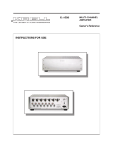
FIGURE 1 THE KAV-1500 FRONT PANEL
KAV- 1500
1 Power Button
2 Power LED

Front Panel Description: KAV-1500
See Figure 1 on page 5
1 Power Button
Use this button to switch the KAV-1500 power from off to the operational mode and
also to switch the 12 VDC output (12 V trigger) on and off.
2 Power LED
The blue power LED illuminates when the amplifier is in the operational mode,
6 Krell KAV-1500 Amplifier

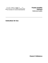
FIGURE 2 THE KAV-1500 BACK PANEL
3 8
AGC-12
20 23 19 14
9
INPUT---~
/
AGC-12
5 10
/
r-~ ~ INPUT ~
/
6 11 7 12
KAV-1500
Power Amplifier
21 22
OUTPUT
(LIEF’I" SURROUNO)
19 15 1916 1917
AGC42
OUTPUT
(LEF’r)
1918
Balanced Inputs
3 Right Surround Input
4 Left Surround Input
5 Center Input
6 Right Input
7 Left Input
Single-ended Inputs
8 Right Surround Input
9 Left Surround Input
10 Center Input
11 Right Input
12 Left Input
Multi-Channel Input
13 Multi-channel Input
Amplifier Channel Outputs
14 Right Surround Output
15 Left Surround Output
16 Center Output
17 Right Output
18 Left Output
Fuses
19 AGC-~uses "-,
20 Line Fuse
Remote Connections
21 12 VDC Remote
Power Out
22 12 VDC Remote
Power In
Power
23 AC Power Cord

Back Panel Description: KAV-1500
See Figure 2 on page 7
The KAV-1500 back panel provides connections for all inputs and outputs, remote
connection input and output links, and AC power supply.
Balanced Inputs
3, 4, 5, 6, 7 Inputs
These are the right surround (3), left surround (4), center (5), right (6), and
KAV-1500 channel inputs for output devices with balanced XLR connectors.
Single-ended Inputs
8, 9, 10, 11, 12 Inputs
These are the right surround (8), left surround (9), center (10), right (11), and left
KAV-1500 channel inputs for output devices with single-ended RCA connectors.
See Reconfiguring the KA V-1500 for MAT, on page 14, and Reconfiguring the
KAV-1500 for Bridged Operation, on page 16, for information on optional system
configurations.
Multi-channel Input
13 Multi-channel Input
This is the DB-25 input, for connecting to the DB-25 output of a preamp/processor. The
DB-25 input incorporates all five channels plus a 5 VDC (5 Volt trigger), and allows you
to send all audio signals and turn the amplifier on and off via a single cable.
Amplifier Channel Outputs
14, 15, 16, 17, 18 Outputs
These are the right surround (14), left surround (15), center (16), right (17), and left
KAV-1500 amplifier channel outputs with five-way loudspeaker binding posts. The
loudspeaker binding post terminals accept spade lugs, bare wire, banana plugs, or
pins. Use the red terminal for the positive connection and the black terminal for the
negative connection.
See Input and Output Connections, on page 10, Connecting the KA V-1500
Reconfigured for MAT, on page 14, and Connecting the Bridged KA V-1500, on
page 17, for more information on amplifier channel output connections.
8
Krell KAV-1500 Amplifier

Back Panel Description, continued
Fuses
19 AGC-12 Fuses
The AGC 12 Volt loudspeaker fuses protect the KAV-1500 against short circuits in
loudspeaker output.
20 Line Fuse
The line fuse protects the KAV-1500 against short circuits in internal power supplies,
Note
Fuses must be replaced with the fuse value specified on the KA V-1500 back panel
Use a 20 amp slow-blow line fuse for 100/120 V systems or a 12 amp slow-blow line
fuse for 220/240 V systems,
Remote Connections
21 12 VDC Remote Power Out
The KAV-1500 is equipped with an output that sends 12 VDC power on/off (12
trigger) signals to other Krell components and other devices that incorporate a 12
trigger.
22 12 VDC Remote Power In
The KAV-1500 is equipped with an input that receives 12 VDC power on/off (12
trigger) signals from other Krell components and other devices that incorporate a 12
trigger. This allows you to turn the KAV-1500 on and off using a Krell or other
component in a custom installation.
Notes
12 VDC Out~In (12 V trigger) remote power is limited to 30 ma.
Consult the owner’s manual of each component used in a custom installation to take full
advantage of the KA V-1500 remote capability.
Power
23 AC Power Cord
The KAV-1500 is equipped with a hardwired AC power cord,
Krell KAV-1500 Amplifier

Connecting the KAV-1500 Amplifier to Your System
INPUT AND OUTPUT CONNECTIONS
Follow these steps to connect the KAV-1500 amplifier to your system.
1. Make sure all power sources and components are off before connecting inputs and
outputs=
2.
Neatly organize the wiring between the amplifier and all system components.
Separate AC wires from audio cables to prevent hum or other unwanted noise from
being introduced into the system,
3. Connect the interconnect cables from your output device to the amplifier inputs. The
KAV-1500 is equipped with balanced (3, 4, 5, 6, 7) or single-ended (8, 9, 10, 11,
inputs located on the back panel. The balanced inputs use three-pin XLR
connectors; the single-ended inputs use RCA connectors.
or
Use the multi-channel (DB-25) connector to simplify the integration of the KAV-1500
into your system.
Connect the DB-25 output on your preamp/processor to the DB-25 input (13)
located on the back panel of the KAV-1500. The DB-25 cable simultaneously
transmits audio outputs and Trigger 1 signals from the Krell Home Theater Standard
Surround Preamp/processor (HTS) DB-25 output to all inputs and a 5 VDC (5 Volt
trigger) on the KAV-1500 via the DB-25 input.
Note
You need to configure Trigger 1 on the HTS before operation.
IMPORTANT
Do not connect the multi-channel input and single-ended or balanced inputs at the
same time.
4. Connect the loudspeaker cables to the KAV-1500 amplifier channel output speaker
binding posts (14, 15, 16, 17, 18)located on the back panel.
The amplifier channel outputs for the KAV-1500 use five-way loudspeaker binding
posts. The loudspeaker binding post terminals accept spade lugs, bare wire, banana
plugs, or pins. Use the red terminal for the positive connection and the black
terminal for the negative connection.
5. Plug the end of the AC power cord into the AC outlet.
The amplifier is now ready for operation. See Amplifier Operation, on page 19.
1 o
Krell KAV-1500 Amplifier

The KAV-1500 amplifier is shipped with shorting pins in the XLR inputs. These pins
should remain in the XLR inputs if the amplifier is operating in the single-ended mode.
When the shorting pin is insert,ed, pins 1 (lower left) and 3 (top) are shorted together.
Remove the shorting pins to connect the amplifier for balanced operation.
The XLR pin configuration is described below:
Pin 1 Ground
Pin 2 Non-inverting (0
°)
Pin 3 Inverting (180
°)
Krell recommends using balanced interconnect cables. Balanced interconnect cables
not only can minimize sonic loss but are also immune to induced noise, especially with
installations using long cables. Balanced connections have 6 dB more gain than single-
ended connections. When level matching is critical, keep this gain value in mind.
Krell KAV-1500 Amplifier
11

Optional System Configurations
The KAV-1500 can be reconfigured for either Multi Amp Throughput (MAT) or bridged
operation.
IMPORTANT
Removing the cover to reconfigure for MAT or for bridged operation is the ONLY
instance you are authorized to remove the cover of ANY Krell component without
voiding your Warranty. For more information on product limitations and restrictions, see
Warranty, on page 21.
Before Reconfiguring for MAT or Bridged Operation
Read the following important safety instructions before you attempt to reconfigure your
amplifier for either MAT or bridged operation:
1. Unplug the power cord. Unplug the AC power cord (23) from AC power.
2.
Avoid the power supply. After removing the screws (see instructions below) and
the cover, locate and stay aware of the location of the power supply (round, silver
structures behind the amplifier front panel). Avoid making contact with that area of
the amplifier.
3. Remove jewelry. Rings, necklaces, bracelets, and other pieces of metal jewelry
can conduct an electrical charge. Consider removing them before attempting any
reconfiguration.
4. Always replace cover, Make sure the amplifier’s cover is properly replaced and
secured by all 14 cover screws before resuming operation.
IMPORTANT
Operating the amplifier without the cover properly replaced and secured may
void your warranty.
MULTI AMP THROUGHPUT
Multi Amp Throughput (MAT) is an internal connection option for the KAV-1500 that
lets you send the same music signal to all amplifier channels using one balanced or
single-ended connection. MAT reduces installation complexity and cabling requirements
in systems containing multiple amplifiers.
12
Krell KAV-1500 Amplifier

FIGURE 3 RECONFIGURING THE KAV-1500 FOR MAT OPERATI()N
PC Input Board showing MAT jumper configuration
Left To Slow
Channel
Start
J1M
8oard
For J For ~,~eff. SurroundJ For~ Right
Bridging
Surround
J6fl J4
N
,,,J5 J7111 J12,, J11,llJ1,II J13,1, J1811 Jr6111 CRj17 I~L~piiTB~5/~ES J~i
’ng
J19~ ~J23 ~:0~i~2~
I]J29 IIIJ25
PRC - Permanent ribbon connections (Do Not Remove)
MAT - Multi Amp Throughput (MAT) ribbon connections

Reconfiguring the KAV-1500 for MAT
See Figure 3 on page 13
Tools needed: T-15 Torx wrench and four ribbon connection cables
1. Turn the KAV-1500 off by pressing the power button (1) on the front panel. The blue
power LED (2) extinguishes. Unplug the AC power cord (23) from AC power.
2. Using the T-15 Torx wrench, remove the 14 screws that secure the amplifier cover.
Carefully remove the cover.
3. Locate the PC input board and jumper pins at the rear of the amplifier.
IMPORTANT
Do not remove or change the ribbon connection cables already in place. These
connections are polarized to ensure the correct phase.
4.
Connect one end of the first ribbon connection cable to jumper pin J5. Connect the
other end of the ribbon connection cable to jumper pin J11.
5. Use the remaining ribbon connection cables to connect:
J10 to J16
J 17 to J22
J23 to J28
6. Replace the cover, sliding the front panel end in first and, using the T-15 Torx
wrench, secure all 14 cover screws.
The KAV-1500 amplifier is now reconfigured for MAT operation.
Connecting the KAV-1500 Reconfigured for MAT
See Figure 2 on page 7
1. Connect your output device to one of the balanced inputs (3, 4, 5, 6, or 7) or one
the single-ended inputs (8, 9, 10, 11, or 12) on the KAV-1500 back panel.
IMPORTANT
Do not use the multi-channel input if you have reconfigured the KA V-1500 for MAT or
bridged operation.
2. Connect each amplifier channel output (14, 15, 16, 17, 18) to a separate
loudspeaker, using the positive and negative terminals on the speaker binding posts.
14 Krell KAV-1500 Amplifier

FIGURE 4 RECONFIGURING THE KAV-1500 FOR BRIDGED OPERATI( )N
Do not attempt to bridge channels in any way other than specified below.
Opt I
Opt~ Opti°n 2
Right For Center For For
Channel Bridging Channel Bridging
KRELLINDUSTRIES Bridging
J,~ J12fl
J11~11(~] ,13~ J18
H
J16fl H J17 1"%7BOA05B
RD
J24N
!
Left To Slow For
Channel Stad Bridging
m
Board
Option 4
i
Left Surround For Right
Option 1: Bridging
r----BRG
the Left and
Right Channels
,~ Bri~ (~l~;~e, Bri~ing~
/ J6111 J411 II
J5
J7111 J1211 J11111
~__~-- PRC
Option 3: Bridging I-~-BRG
the Center and Left ~....-L....~..~
Surround Channels f
-~
1418111 J1611 II317 P10705B J2411 J19111J2211 111423 I
~__~--- PRC
Option 2: Bridging
r----BRG
the Right and
~
Center Channels
f ~
I
For
/
.....=..X /
/ J12111
J1111J1qlJ13111 J1811 J1611 IIIJ17
Option 4: Bridging
I---BRG
the Left Surround and
~
Right Surround Channels /
~
For
~ Left For~
~
Bridgin~"~Su~und n n Bd~]ing n~
|
324111 31911132211 ii323 3301132811 iii329
~__~-PRC
PRC -- Permanent ribbon connections (Do Not Remove)
BRG -- Bridging

BRIDGED OPERATION
The KAV-1500 can be reconfigured to bridge four of its amplifier channels to operate
as two combined amplifier channels. The bridged amplifier channels each deliver 1,100
Watts into an 8 Ohm load. The unbridged amplifier channel can be connected to a
separate loudspeaker.
IMPORTANT
One channel must remain unbridged.
Reconfiguring the KAV-1500 for Bridged Operation
See Figure 4 on page 15
Tools needed: T-15 Torx wrench and two ribbon connection cables
1. Turn the KAV-1500 off by pressing the power button (1) on the front panel. The blue
power LED (2) extinguishes. Unplug the AC power cord (23) from AC power.
2. Using the T-15 Torx wrench, remove all 14 cover screws that secure the amplifier
cover. Carefully remove the cover.
3.
Locate the PC input board and jumper pins at the rear of the amplifier.
4. Follow the directions below. You may bridge channels using:
Options 1 and 3 or Options 1 and 4 or Options 2 and 4
IMPORTANT
Do not attempt to bridge channels in any way other than specified in these directions.
Option 1: To bridge the left and right channels, connect one end of the ribbon
connection cable to jumper pin J6. Connect the other end of the ribbon connection
cable to jumper pin J11.
Option 2: To bridge the right and center channels, connect one end of the ribbon
connection cable to jumper pin J12. Connect the other end of the ribbon connection
cable to jumper pin J17.
Option 3: To bridge the center and left surround channels, connect one end of the
ribbon connection cable to jumper pin J18. Connect the other end of the ribbon
connection cable to jumper pin J23.
Option 4: To bridge the left surround and right surround channels, connect one
end of the ribbon connection cable to jumper pin J24. Connect the other end of the
ribbon connection cable to jumper pin J29.
5. Replace the cover and, using the T-15 Torx wrench, secure all 14 cover screws.
The KAV-1500 amplifier is now ready for bridged operation.
16 Krell KAV-1500 Amplifier
/