Page is loading ...

User’s Manual
BX-AL133 Anamorphic Lens

User’s Manual
BX-AL133
For more information, please visit our website at:
http://www.OptomaUSA.com
User’s Manual | 2
Safety
1. Read and understand instructions and heed warnings before beginning installation.
2. Mount rail securely. The lens is heavy, and requires a secure and stable surface.
Fasteners in sheetrock alone are not safe. Reciprocal lens motion can and will work
them loose. Use a board, plate, or projector mount fixed to ceiling joists or studs.
3. Anticipate unexpected lens motion. A malfunction can cause the lens to move
unexpectedly. Disconnect the power when installing, working on or repositioning
the lens. While on a ladder, do not stand in the direct path of the lens in case of
unexpected or accidental movement.
4. Do not install the lens in a wet or moist environment, or where the mechanism will be
exposed to extreme or external weather conditions. The lens is for indoor use only.
5. Never pour any liquid or push any object into the enclosure.
6. Do not install in direct path of heater vents or projector exhaust ports. Do not block
any of the vents or holes in the enclosure.
7. The power adaptor is intended for 100- 220 volt, 50-60 cycle AC power only.
8. Do not subject power cord to conditions which will wear through or cut the insulation.
Avoid excessive tension or chafing of the cord.
9. Do not service the motor drive or electronics. There are no user serviceable parts.
Contact your dealer or send to a factory approved facility. Opening the case will void
the warranty.
10. Exercise extreme caution when working on a ladder. Do not work directly above
another person, particularly a child. Plan all work carefully. Accidentally dropping a
drill, hammer, or the lens assembly can cause serious bodily injury.
11. Pushing or forcing the sled by hand may damage the circuit board. Should it be
necessary to move the sled by hand, make sure it is done slowly and lightly.
12. The Optoma motorized sled will ramp up and down at the beginning and end of the
traversal to minimize swaying forces at the mount. As the motor accelerates and
brakes, there is a minimal change in the sound.
This device complies with part 15 of the FCC rules. Operation is subject to the following
two conditions: (1) This device may not cause harmful interference, and (2) this device
must accept any interference received, including interference that may cause undesired
operation.
September 2005 Edition

User’s Manual
BX-AL133
For more information, please visit our website at:
http://www.OptomaUSA.com
User’s Manual | 3
Introduction
Thank you for purchasing the Optoma BX-AL133 anamorphic lens. The lens and
motorized sled is outfitted with a custom mechanism designed exclusively for use in a
home theater environment.
No oil or liquid based lubricants are used to assure the maximum cleanliness of optical
components. Both lens and drive will provide years of maintenance free service. The
Optoma system is built and tested in the USA with the strictest quality standards and
certifications.
Features and benefits:
Easy, straight forward installation and operation
Machined, high-grade, anodized aluminum components
Repeatable precision positioning system
Flexible mounting options for either table top or ceiling mount
Speed selector for high or low speed operation
Configurable “lens in” position
Extra external IR sensor for remote mounting (if needed)
Input 12V jack for automatic lens trigger
Output 12V jack for screen masking trigger
Non-mechanical long life optical stop sensors
Dry operating precision linear bearings
Heavy-duty, high-precision NEMA 23 stepper motor
Custom built, low noise stepper drive circuitry and firmware
Endurance tested to more than 250,000 traversals
8-button long-range (up to 50 feet) remote control with discrete functions
Backlit logo with on/off lighting control
Reversible logo plates
Built and tested in the USA
FCC, CE and UL certified

User’s Manual
BX-AL133
For more information, please visit our website at:
http://www.OptomaUSA.com
User’s Manual | 4
Getting to Know Your System
Status LED Infrared Remote Sensor Mounting Plate Rail
Reversable Logo Plate
Motor Housing Cover
Drive Belt
Rail Bearing (X4)
Lens Adaptor Plate
Pulley Housing Cover
Motorized Sled
OFF
LENS OUT
PANEL OFF
SLOW
ON
LENS IN
PANEL ON
FAST
8-Button Remote Control
Remote IR Sensor
Rear Panel View
+9V DC In
+12V Trigger Out
+12V Trigger In
Remote IR Sensor In
16.5V DC Power Supply

User’s Manual
BX-AL133
For more information, please visit our website at:
http://www.OptomaUSA.com
User’s Manual | 5
Plan Your Installation
The lens assembly may be mounted in one of two ways:
1. To the ceiling or projector mount above the projector
2. To a shelf or table below the projector
When attaching the motor assembly to the ceiling, use a board, plate or lens-enabled projector mount
that is attached to ceiling joists or studs. Sheetrock embedded fasteners can and will become loose
with repeated lens movement, causing the mechanism to fall, resulting in possible severe injury.
Planning for Projector Exhaust
Some projectors have hot air exhaust ports that discharge from the front. Avoid situations where the
lens or housing will block or obstruct the warm air flow out of the projector, as damage to the bulb
and/or the lens may result. You can mount the sled either to the left or right of the lens. During setup,
you can easily configure the “lens-in” position to be on the motor housing or pulley housing side of the
sled. (See Setup).
Changing Orientation of Logo Plate (Optional)
The lens sled is configured for ceiling mounted operation as shipped. As such, the
logo reads right side up with the mounting bar on top. If you are using the
sled in a table or shelf mounted
configuration, you will want to turn
the logo around so that it is right
side up with the mounting bar
below the projector.
To reverse the logo, remove the 4
screws securing the motor housing
cover. Lightly slide the sheet metal
cover and lift it off. Once removed,
you can easily access the logo
plate. Remove the two small
screws securing the logo plate,
turn the plate around, and re-install
the screws. Install the motor cover
housing back on the sled with the
original screws.
The logo backlight may be turned
off using the remote control. An
alternative to reversing the logo
plate is to simply turn off the
back light to make the logo less
conspicuous.
Remove
Screws
Rotate Logo
Upright
Remove Screws
Replace Screws

User’s Manual
BX-AL133
For more information, please visit our website at:
http://www.OptomaUSA.com
User’s Manual | 6
Mounting Sled to Shelf or Ceiling
When installing the motorized sled, make sure that you first mark screw locations using
only the sled−without the lens and/or the lens bracket in place.
Do not rely on fasteners embedded in sheetrock alone. Reciprocal lens movement can
and will work them loose and cause the mechanism to fall. Mount the sled on a plate,
board, or lens-enabled projector mount affixed to ceiling joists for safety.
Once the sled is secure, attach the bracket to the lens adaptor plate. Then, only after
properly aligning and positioning the bracket, power up the sled and check the alignment
again. Finally, attach and adjust the lens to its correct angle and vertical position.
Follow this procedure:
1. Line up the center line of lens
There are score marks on the back of the mounting bar that correspond to the center of
the BX-AL133 expansion lens. Before starting, the projector must be correctly focused
with the zoom and iris set in their viewing positions. This will assure that the front of the
lens is positioned correctly. Hold the motorized sled up to the projector and determine
if the LENS IN position will be on the motor housing (logo side) or the pulley housing
(smaller box) side. This will determine the score mark you will use (see below).
Measure 2-1/8 inches from the front of the projector lens, and lightly draw a line parallel
to the front of the lens. Mark the center line of the projector lens along this parallel line.
Line up the back of the mounting bar to the parallel line just marked. Align the center of
the projector lens mark with the correct score line on the mounting bar, and mark the six
drill hole locations using the mounting bar itself as a template. Drill out the holes for the
fasteners.
Front of Projector Lens
(Zoomed and Focused)
Lens Center Line
Mark for DrillMark for Drill Mark for Drill
Motor Housing Side
Score Mark
Pulley Housing Side
Score Mark
2.125”

User’s Manual
BX-AL133
For more information, please visit our website at:
http://www.OptomaUSA.com
User’s Manual | 7
2. Securing the mounting plate
Because the mechanism and lens are heavy, make sure the mounting fasteners and
surface are extremely secure. Remember that the sled motor will be starting and
stopping a heavy weight thousands of times through normal use. Ceiling mounted lenses
require a secure surface.
Sheetrock anchors alone are insufficient. Secure the mounting bar to a plate, painted
board, or lens-enabled projector mount that is securely affixed to the studs or ceiling
joists.
Use of a commercial mounting system enabled for anamorphic lenses is highly
recommended. Use all six screw holes, and tighten fasteners securely. Vibration from
the motor and reciprocal lens movement will loosen any fasteners that are not absolutely
tight and secure.
Do not attach the lens or power up the sled yet! Adjustment and alignment are much
easier at this point without the lens.
3. Attaching the lens bracket to the adaptor plate
Remove the bracket mounting screws from the inside holes in the adaptor plate and
use them to attach the lens bracket supplied with the Optoma BX-AL133 anamorphic
lens system. If the lens is attached to the bracket, make sure to remove the lens prior to
attaching to the lens adaptor plate.
Holes for Ceiling or Plate
Mount (x6) Fasteners
Lens Bracket Screws (x4)

User’s Manual
BX-AL133
For more information, please visit our website at:
http://www.OptomaUSA.com
User’s Manual | 8
Setup
1. Power up the sled and set LENS IN position
Slide the lens into the middle of the sled before powering up. Plug the power adaptor into an AC
outlet, then into the back of the unit as illustrated. Using the remote, press the “lens in” button. The
lens sled will slowly position itself into the factory default LENS IN position. The edge of the adaptor
plate will land about a half-inch from the motor housing side of the sled. If the bracket is in front of the
projector lens, proceed to the next step (Verify centering).
If the bracket is not in front of the projector lens, you will need to change the setting. Simply press
the LENS OUT button on the remote, and wait for the bracket to move in front of the projector lens.
Press and hold the LENS OUT button again for 5 seconds. The sled will confirm the new setting by
moving the bracket away from the projector lens to the new LENS OUT location. The edge of the
adaptor plate will land about a half-inch from the motor housing side of the sled. You have now re-
programmed the sled. This setting will be preserved in the unit even if it is unplugged or undergoes a
power failure. To change back, just repeat the above procedure.
2. Verify centering
Press LENS IN and see where the lens stops. If needed, make small adjustments (+ or – a quarter-
inch) to the lens bracket after disconnecting the power, by loosening the screws and sliding the
bracket to the left or right as
needed to achieve centering.
Reconnect the power and check
the centering. The optical sensors
will stop the edge of the lens
adaptor plate approximately a half-
inch from the housing on either side
of the sled. You can use this gap
on the motor or the pulley side for
fine-tuning adjustments.
Rear Panel View
+9V DC In
+12V Trigger Out
+12V Trigger In
Remote IR Sensor In
OFF
LENS OUT
PANEL OFF
SLOW
ON
LENS IN
PANEL ON
FAST
0.5” Gap
Projector Lens

User’s Manual
BX-AL133
For more information, please visit our website at:
http://www.OptomaUSA.com
User’s Manual | 9
3. Attaching the lens to the bracket
Attach the Optoma BX-AL133 anamorphic lens to the bracket using the plastic knobs
supplied with the lens. Adjust the anamorphic lens vertically for correct alignment. When
the image is correct, tighten the knobs against the bracket. Using the remote, test run
LENS IN and LENS OUT commands.
4. Configuring the lens speed
The lens has two operating speed modes – FAST and SLOW. Slow is the default from
the factory. The slow mode reduces the inertia exerted by the lens on the mounting
system by accelerating and decelerating very slowly, and by limiting the top speed of the
lens as it traverses the sled.
If the sled is on a very rigid mount that is not
subject to any sway, you can speed up the
traversal speed by setting the lens speed to FAST.
If you notice any swaying in the mounting, reset
the speed to SLOW.
Some users set the speed to SLOW when used in
conjunction with screen masking systems. Your
speed setting will be “remembered” by the control
unit even if the power is interrupted.
Congratulations, you are now ready to experience
widescreen cinema from your home theater.
Tighten Knobs
OFF
LENS OUT
PANEL OFF
SLOW
ON
LENS IN
PANEL ON
FAST

User’s Manual
BX-AL133
For more information, please visit our website at:
http://www.OptomaUSA.com
User’s Manual | 10
Remote Control and Motor Operation
The LED indicator on the sled will glow when the unit is ON, and flash when any button is
pressed. It will also flash when the lens is in motion. The LED will be off in standby mode.
Buttons:
OFF – Puts the sled in standby mode.
ON –Turns the sled from standby to ON.
LENS OUT – Commands the lens to move
into the LENS OUT position.
Holding the button for several seconds
re-programs the current position as the
new LENS IN position. The lens sled will
acknowledge the request by flashing the
LED and moving the lens to the new LENS
OUT position (the opposite side).
LENS IN – Commands the lens to move
into the LENS IN position (as configured in
Setup).
PANEL OFF – Turns the logo backlight off.
PANEL ON – Turns the logo backlight on.
SLOW – Sets the acceleration/deceleration
and maximum speed for slow (low inertia)
traversal.
FAST – Sets the acceleration/deceleration
and maximum speed for rapid traversal.
OFF
LENS OUT
PANEL OFF
SLOW
ON
LENS IN
PANEL ON
FAST
8-Button Remote Control

Rear Panel View
+9V DC In
+12V Trigger Out
+12V Trigger In
Remote IR Sensor In
To screen
masking system
From projector
or scaler
User’s Manual
BX-AL133
For more information, please visit our website at:
http://www.OptomaUSA.com
User’s Manual | 11
Rear Panel − Triggers and Sensors
To use the automatic lens trigger, your projector or scalar must be equipped with a lens
trigger and a standard double-ended 3.5 mm (1/8 inch) male mono or stereo jack cable.
Simply plug the cable into the projector’s lens trigger jack and into the sled +12V Trigger-
In jack. Follow the projector or scalar instructions to configure the lens trigger.
The Trigger-In (tip positive) operates as follows:
+12V LENS IN command
0V LENS OUT command
NOTE: The input trigger jack may be temporarily overridden by the remote control. When
the next transition of voltage occurs (up or down), the trigger will take control once
again.
Another option allows you to use the +12V Trigger-Out jack on the rear of the device. The
output jack is set to +12V whenever the sled is in the LENS OUT position.
This is typically used for triggering screen masking systems to mask the side of the
screen when an HDTV (16:9) image is being projected instead of a widescreen (2.35:1)
DVD movie format.
The Trigger-Out jack (tip positive) operates as follows:
0V Lens is in the LENS IN position
+12V Lens is in the LENS OUT position
Each sled is supplied with an optional remote IR sensor which may be used to improve
reception if the sled is located where IR signals cannot be reached. It may also be used
with an IR repeater system by simply taping the remote sensor to one of the IR emitters
from the repeater system.
To use, simply peel
off the included self-
stick tape, affix to a
convenient location
and plug the 2.5
mm cable into the
appropriate jack in
the back of the unit.

User’s Manual
BX-AL133
For more information, please visit our website at:
http://www.OptomaUSA.com
User’s Manual | 12
Cleaning and Maintenance
The Optoma BX-AL133 anamorphic lens system is maintenance-free. It will deliver many
years of trouble-free service as delivered from the factory.
To clean: Lightly blow off any surface debris from the lens. If needed, clean the lens
using standard cleaning supplies while the projector is on (be careful not to look directly
into the light beam of the projector.
Clean the metal components with a damp cloth, make sure not to drip any water into the
enclosure.
The sled internal drive is permanently coated to run smoothly. Keep the rail linear bearing
clean, dry and contaminant free.
In case of accidental debris and/or liquids spilled onto the system, you can clean all
contaminants with water and wipe down with denatured alcohol. The drive mechanism
relies upon a clean rail to operate smoothly.
The linear bearing, and all enclosed bearings are constructed of specialized material to
ensure smooth operation. Remove power source before cleaning. Outside lubricants
will gum up the mechanism, and possibly produce a film across the projector and
anamorphic lens.
Never use lubricants of any nature on any part of the mechanism.

User’s Manual
BX-AL133
For more information, please visit our website at:
http://www.OptomaUSA.com
User’s Manual | 13
Specifications
Electrical Characteristics
Model Optoma BX-AL133 Motorized Sled
Power Supply 110/120v, 50-60 Cycles
Power Supply Output 9V DC, 0.5A
Operating Voltage 9-18V DC, 0.5-1.5A
Operating Current Draw Typical 650mA, max 1.2A
Standby Current Draw 60mA
Trigger Jack 3.5 mm Mono or Stereo Jack, 12V, Tip Positive
Remote IR Jack 2.5 mm Stereo Jack (Supplied)
Remote 3oz, IR Emitter
IR Receivers 2, One Fixed, Another Remotely Attached (Optional)
IR Range 50 ft from IR Sensor
IR Carrier Frequency 38 kHz
Batteries 2 AAA (for Remote)
Certification FCC, CE (BX-AL133 Motor Drive Unit)
UL Class II (Power Supply Only)
Design Life Greater than 250,000 rail traversals
Physical Characteristics
Weight 5 lbs
Dimensions See accompanying drawings

User’s Manual
BX-AL133
For more information, please visit our website at:
http://www.OptomaUSA.com
User’s Manual | 14
Dimensions
1.079”
1.52”
.25”
13.738”
5.094”
4.97”
6.921”
5.973”
5.519”
3.402”
3.579”
4.511”
Ø.25”
8.333”
5.375”
2.5”
7.25”
10.842”
Score Mark
(Pulley Side)
Score Mark
(Motor Side)
19.675”
3.0”
7.705”

User’s Manual
BX-AL133
For more information, please visit our website at:
http://www.OptomaUSA.com
User’s Manual | 15
Warranty
Optoma Technology Inc. warrants this product to be free of defects in original
workmanship and material for a period of twenty-four (24) months from
the date of purchased. During this period, a defective unit may be repaired
or replaced, at the discretion of Optoma Technology Inc., by returning it in
its original packaging with a copy of your receipt. This warranty does not
cover damage resulting from tampering, lack of prudent care, accident or
misuse (including contravention of cautions stated in the instructions), or
any cosmetic damage not reported within fifteen (15) days of purchase.
All liability for damage is limited to the cost of the product and does not
include incidental injury or peripheral damage to other equipment, persons
or property. Optoma Technology Inc. is not responsible for personal injury
resulting from faulty installation. A service charge may be applied to any
returned product requiring cosmetic attention, or to the repair of any damage
not covered under this warranty.

User’s Manual
BX-AL133
For more information, please visit our website at:
http://www.OptomaUSA.com
User’s Manual | 16
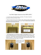
Addendum: Adapter Plate
This attachment plate is designed to be installed onto a ceiling mounted projector. The
location or orientation of the ceiling mount does not need to change.
Contents
1 Lens Plate
1 (Bag) Projector Attachment Parts
1 Assembly Kit (Includes)
2 Plate Hook Assemblies
1 Chain (6 ft)
4 Chain Ends
4 Lens Mounting Assemblies
4 Sled Mounting Screws
2 Sled Safety Assemblies
1 Hex Key
Required Tools and Equipment
2 Ceiling Hooks (40 lbs Capacity Each)
1 Phillips Screwdriver
1 Pair of Pliers
1 Strong Pair of Scissors or Wire Cutters
1. INSTALL PLATE HOOK ASSEMBLIES. Use the pliers to bend the closed-end of the
hooks apart just enough to insert the end of the chain. Install the plate hook assemblies
in the two holes. Place one hook end on the top side and then continue the assembly
down in the order of nut, washer, lens plate, washer, lock washer and nut. Arrange the
assembly so that the plate is in the center of the threaded hook shaft.
2. ATTACH LENS PLATE. Remove the projector from the ceiling and the ceiling mount
adapter plate. Position the ceiling mount adapter plate over the lens plate and the
projector. Line up the holes of the lens plate (labeled holes for projector and ceiling
mount in the diagram above) with the holes of the ceiling mount and projector. Install the
silver screws from the attachment parts bag.
Ceiling mount hardware may vary. If the provided screws are not long enough,
purchase the longest metric M4 screws without exceeding the depth of the projector
mounting holes for the greatest security.
3. MOUNT PROJECTOR ASSEMBLY. Securely connect the ceiling mount adapter, lens
plate and projector assembly to the ceiling mount and then adjust the ceiling mount to
provide the proper 16:9 image orientation in the center of your 2.35:1 screen.
Lens Plate
Holes For:
Projector and Ceiling Mount
Hooks
Lens Only
Motorized Sled
Front
Ceiling Side (Top)

User’s Manual
BX-AL133
For more information, please visit our website at:
http://www.OptomaUSA.com
User’s Manual | 17
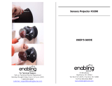
4. INSTALL CHAINS. Hold the chain to the ceiling so that one end of the chain hangs
just above one of the installed plate hooks. Mark the ceiling location and repeat for the
other chain hook. Procure and install the ceiling hooks at those locations small enough
to accept a chain end, and strong enough when installed to support approximately 40
pounds (or more). The type of hook and method of installation may depend on the type
of ceiling you have. Cut the chain to make chain segments. The ones that come closest
to supporting the lens plate when attached to the chain ends should be the ones that
are attached to the plate and ceiling hooks. Install the lens chains and adjust the nuts
on the plate hooks to make the chains tight, but without raising the front of the plate.
Tighten the plate hook nuts to compress the lock washer in the plate hook assembly.
5. MOUNT THE ANAMORPHIC LENS.
INSTALLATION WITHOUT THE MOTORIZED MOUNT:
a. Remove the lens from its lens bracket.
b. Orient the lens bracket to the lens plate so that the angled sides of the lens
bracket are toward the back of the plate. Install the four lens mount assemblies
(large assemblies with white spacers) from the top down through the four holes
that are for the lens in the order of screw, flat washer, lens plate, white spacer,
lens bracket, flat washer, lock washer and nut. Use the hex key to tighten the
nuts so that the lens mount assemblies are centered in the elongated lens bracket
holes.
c. Turn the projector on and project a full, yet still 16:9 image from the projector.
Carefully install the lens and adjust the tilt to equalize the top and bottom image
geometry while positioning the lens vertically to center the output beam. Tighten
the lens knobs.
INSTALLATION WITH MOTORIZED MOUNT:
a. Do Not Connect the Power of the Motorized Mount at this Time.
b. Position the motorized mount on the bottom side of the lens plate so that the six
holes (refer to the diagram on the previous page) in the lens plate line up with
the six holes in the flat side of the motorized mount. Insert the four small 1/4”
screws through the four small holes of the lens plate into the motorized mount and
tighten.
c. Insert the sled safety assemblies through the remaining two holes from bottom up
in the order of screw, motorized mount, lens plate, washer, lock washer and nut.
Tighten both safety assemblies.
d. Refer to the motorized mount user manual for additional instructions at this time.
Use extreme caution and appropriate hardware when installing heavy objects to a
ceiling. Periodically check all fasteners and connection hardware to be sure they have
not come loose. Improper installation may lead to an increased risk of your equipment
becoming unstable and possibly causing injures.

User’s Manual
BX-AL133
For more information, please visit our website at:
http://www.OptomaUSA.com
User’s Manual | 18
Addendum: The Finished Product

Optoma Technology, Inc.
715 Sycamore Drive, Milpitas CA 95035
TELs&AX
&ORMOREINFORMATIONPLEASEVISITWWW.Optoma.com.
Specifications subject to change without notice. Copyright 2007 Optoma Technology, Inc.
USA
715 Sycamore Drive
Milpitas, CA 95035, USA
Tel: 408-383-3700
&AX
WWW.OptomaUSA.com
#ANADA
+ENNEDY2OAD
-ISSISSAUGA/.,:!#ANADA
TEL
&AX
WWW.Optoma.com
/