Page is loading ...

USE AND CARE GUIDE
Questions, problems, missing parts? Before returning to the store,
call Home Decorators Collection Customer Service
8 a.m. - 7 p.m., EST, Monday - Friday, 9 a.m. - 6 p.m., EST, Saturday
1-800-986-3460
HOMEDEPOT.COM/HOMEDECORATORS
RAVENSDALE MEDIA UNIT
1001369827/88928Y/23MM20206-PA01
XXX XXX/88928/23MM20206-PA01
XXX XXX/89406/23MM20206-PW07
XXX XXX/89406/23MM20206-PD01
We appreciate the trust and condence you have placed in Home Decorators through the purchase of this electric replace. We strive to
continually create quality products designed to enhance your home. Visit us online to see our full line of products available for your home
imporvement needs. Thank you for choosing Home Decorators!
THANK YOU

2
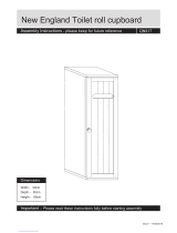
Maximum Load Warning
MAXIMUM LOAD 45 lb. (20.4 kg)
MAXIMUM LOAD 20 lb. (8.8 kg)
MAXIMUM LOAD 45 lb. (20.4 kg)
MAXIMUM LOAD 15 lb. (6.8 kg)
Table of Contents
CAUTION:
This unit is intended for use only with the products and maximum weights indicated. Use with other products or products heavier
than the maximum weights indicated may result in instability causing possible injury.
NOTE:
Flat Panel TVs with base support should be placed squarely in the center of the stand with no overhang on any side.
Maximum Load Warning ........................................... 2
Safety Information ..................................................... 3
Warranty ..................................................................... 5
Pre-Assembly .............................................................6
Hardware Included ................................................... 6
Product Specications ....................................................... 6
Tools Required ................................................................... 6
Package Contents .............................................................. 7
Assembly .................................................................... 8
Operation .................................................................19
FCC/IC Information ......................................................... 21
Care & Cleaning ....................................................... 21
Troubleshooting ....................................................... 22
Replacement Parts ..................................................24

3
HOMEDEPOT.COM/HOMEDECORATORS
Please contact 1-800-986-3460 for further assistance.
Please read and understand this entire manual before
attempting
to assemble, operate or install the product. If you
have any question regarding the product, please call customer
service at service at 1-800-986-3460, 8 a.m.-7 p.m., EST,
Monday-Friday, 9 a.m. - 6 p.m., EST, Saturday.
When using electrical appliances, basic precautions should
always be followed to reduce the risk of re, electrical shock,
and injury to persons including the following:
1. Read all instructions before using this appliance.
2. If possible, always unplug this appliance when not in use.
3. Only a qualied service person should repair this product.
4. Do not use outdoors.
5.
Do not cover the cord under the carpeting. Do not cover
with throw rugs, runners or the like. Arrange the cord away
from trafc areas and where it will not be tripped over.
6. To disconnect this appliance, turn the controls to the off
position, and then remove the plug from the outlet.
7. Connect to properly grounded outlets only.
8.
This appliance, when installed, must be electrically
grounded in accordance with local codes or, in the
absence of local codes, with the current CSA C22.1
Canadian Electrical Code. For U.S.A. installations, follow
local codes and the National Electrical Code, ANSI/NFPA
NO.70.
9. This appliance has hot and arcing or sparking parts inside.
Do not use it in areas where gasoline, paint or ammable
liquids are used or stored. This replace should not be
used as a drying rack for clothing. Do not hang Christmas
stockings or other decorations on or near this product.
10. There is a thermostat limiter inside the heater. When inner
temperature overheating or abnormal heating occurs, the
thermostat protective device will cut off the power supply
to avoid damage to the replace or risk of re.
Safety Information
DANGER:
High temperatures may be generated under
certain abnormal conditions. Do not partially or fully cover
or obstruct the front of this heater.
WARNING:
If the supply cord is damaged, it must be replaced
by the manufacturer, its service agent or similarly qualified
persons in order to avoid a hazard.
WARNING:
Under no circumstances should this fireplace be
modified. Parts that must be removed for servicing must be re-
placed prior to operating this replace again.
WARNING:
In order to avoid overheating, do not cover the
heater.
WARNING:
Use extreme caution when operating heater
near children and the disabled.
WARNING:
Do not insert or allow foreign objects to enter
any ventilation or exhaust opening as this may cause an electric
shock or re, or damage the appliance.
WARNING:
To prevent a possible re, do not block air intakes
or exhaust in any manner. Do not use on soft surfaces, like a bed,
where the opening may become blocked.
WARNING:
This appliance has hot and arcing or sparking parts
inside. Do not use it in areas where gasoline, paint or ammable
liquids are used or stored. This replace should not be used as a
drying rack for clothing. Do not hang Christmas stockings or other
decorations on or near this product.
WARNING:
Use this appliance only as described in the manual.
Any other use not recommended by the manufacturer may cause
re, electric shock or injury to persons.
WARNING:
This heater is not intended for use in bathrooms,
laundry areas and similar indoor locations. Never locate this
appliance where it may fall into a bathtub or other water container.
WARNING:
This appliance is not a toy. Supervise children
playing near it.
WARNING:
This appliance is hot when in use. To avoid
burns, do not touch hot surfaces with bare skin. If provided,
use handles when moving this appliance. Keep combustible
materials, such as furniture, pillows, bedding, papers, clothes
and curtains at least 3 ft. (0.9 m) from the front of this appliance.
WARNING:
This heater may include a visual alarm to warn
that parts of the heater are getting excessively hot. If the
alarm flashes immediately turn the heater off and inspect for
any objects on or adjacent to the heater that may cause high
temperatures.
DO NOT OPERATE THE HEATER WITH THE ALARM FLASHING!
CAUTION:
Never leave the heater operating unattended.
Extreme caution is necessary if unsupervised children or invalids
are nearby.
CAUTION:
Before assembly, carefully use scissors or a utility
knife to cut and unwrap all parts. Make sure you do not discard
the hardware.

4
Safety Information (continued)
NOTE:
To avoid injury from unexpected starting or electrical
shock, do not plug the power cord into a source of power during
unpacking and assembly. The cord must remain unplugged
whenever you are adjusting/assembling the replace.
If any part is missing or damaged, do not attempt to use or
plug in the power cord until the missing or damaged part is
correctly replaced. To avoid electric shock, use only identical
replacement parts when servicing double-insulated tools.
NOTE:
Use care in assembling your new fireplace. Take your
time and use the hardware provided and a quality Phillips head
screwdriver. Never overtighten bolts.
• Do not sit on any part of the mantel.
NOTE:
SAVE THESE
INSTRUCTIONS

5
HOMEDEPOT.COM/HOMEDECORATORS
Please contact 1-800-986-3460 for further assistance.
Warranty
1 Year Limited Warranty: The manufacturer warrants that your new Electric Fireplace is free from manufacturing and material defects for
a period of one year from date of puchase, subject to the following conditions and limitations.
1. Install and operate this appliance in accordance with the installation and operating instructions furnished with the
product at all times. Any unauthorized repair, alteration, willful abuse, accident, or misuse of the product shall nullify
this warranty.
2. This warranty is non-transferable, and is made to the original owner, provided that the purchase was made through
an authorized supplier of the product.
3. The warranty is limited to the repair or replacement of part(s) found to be defective in material or workmanship,
provided that such part(s) have been subjected to normal conditions of use and service, after said defect is conrmed
by the manufacturer’s inspection.
4. The manufacturer may, at its discretion, fully discharge all obligations with respect to this warranty by refunding
the wholesale price of the defective part(s).
5. Any installation, labor, construction, transportation, or other related costs/expenses arising from defective part(s),
repair, replacement, or otherwise of same, will not be covered by this warranty, nor shall the manufacturer assume
responsibility for same.
6. The owner/user assumes all other risks, if any, including the risk of any direct, indirect or consequential loss or
damage arising out of the use, or inability to use the product, except as provided by law.
7. All other warranties – expressed or implied –with respect to the product, its components and accessories, or any
obligations/liabilities on the part of the manufacturer are hereby expressly excluded.
8. The manufacturer neither assumes, nor authorizes any third party to assume on its behalf, any other liabilities with
respect to the sale of the product.
9. The warranties as outlined within this document do not apply to non accessories used in conjunction with the
installation of this product.
10. This warranty gives you specic legal rights, and you may also have other rights which vary from state to state.
This warranty is void if:
a. The replace is subjected to prolonged periods of dampness or condensation.
b. Any unauthorized alteration, willful abuse, accident, or misuse of the product.
c. You do not have the original receipt of purchase.

6
Pre-Assembly
HARDWARE INCLUDED
DD
CC
EE
FF GG HH
II JJ KK LL MM NN
Part Description Part Number Quantity
AA Short Flathead Screw N/A 16
BB Camlock Bolt PH-KDBZNC002 43
CC Floor Glide (Pre-attached) PH-GLDBRW001 5
DD Knob (with Screw) N/A 2
EE Shelf Pin PH-SPNPCSPLB2 8
FF Euro Hinge N/A 4
GG Long Flathead Screw N/A 13
HH Metal Plate (Pre-attached) PH-PLBLK001 2
II Door Bumper PH-BMPCLR001 4
JJ Washerhead Screw N/A 44
KK Wood Dowel PH-DWLNTL001 47
LL Camlock PHKDCZNC002 43
MM Hinge N/A 8
NN Tipping Restraint Hardware PH-BKTWHT003 2
ZZ Touch-up Pen N/A 1
NOTE:
Hardware not shown to actual size.
Phillips Screwdriver
AA BB
ZZ
PRODUCT SPECIFICATIONS
VOLTAGE 120VAC, 60 Hz
AMPS 12.5 Amps
WATTS
1500 Watts
PLANNING ASSEMBLY
Before beginning assembly of product, make sure all parts are present. Compare parts with Hardware Included and Package Contents lists.
If any part is missing or damaged, do not attempt to assemble, install or operate the product. Contact customer service for replacement
parts.
Estimated Assembly Time: 60 Minutes
TOOLS REQUIRED

7
HOMEDEPOT.COM/HOMEDECORATORS
Please contact 1-800-986-3460 for further assistance.
Part Description Quantity
A Top Base Panel 1
B Center Shelf 1
C Middle Front Panel 1
D Center Left Side Panel 1
E Center Right Side Panel 1
F Left Front Panel 1
G Top Assembly 1
H Right Front Panel 1
I Left Side Panel 1
J Right Side Panel 1
K Left Base Panel 1
L Right Base Panel 1
M Back Base Panel 2
N Front Base Panel 1
O Divider 1
P Decorative Front Panel 2
Q Decorative Side Panel 2
R Center Back Panel 1
S Outer Back Panel 2
T Left Door 1
U Right Door 1
V Adjustable Shelf 2
W Insert Securing Block 1
X Fireplace Insert 1
X
PACKAGE CONTENTS
Pre-Assembly (continued)
NOTE:
All panels are labeled left
and right as viewed from the front of
unit.
A
WI
V
S
C
B
Q
P
R
G
P
O
Q
N
K
T
U
L
M
D
E
V J
S
F
H

8
3
1
2
G
P
P
KK
LL
P
P
BB
BB
Assembly
QQ
Turn the Top Assembly (G) upside down.
Using a Phillips Screwdriver, screw in the
Camlock Bolts (BB). Turn clockwise.
Preparing the top assembly
Insert Camlock Bolts (BB) into the pre-drilled holes in
the Decorative Front Panels (P) using a Phillips
Screwdriver.
Preparing the decorative front
panels
Insert Wood Dowels (KK) into the pre-drilled holes in
the Decorative Side Panel (Q).
Push the Decorative Front Panel (P) and Decorative Side
Panel (Q) together.
Insert Camlocks (LL) into the pre-drilled holes and turn
clockwise with the Phillips Screwdriver, to lock in place.
Attaching the decorative front
panels

9
HOMEDEPOT.COM/HOMEDECORATORS
Please contact 1-800-986-3460 for further assistance.
Assembly (continued)
Insert the Camlock Bolts (BB) and the Wood Dowels (KK)
into the pre-drilled holes in the Top Assembly (G).
Push the Decorative Side Panels (Q) and the Divider (O)
together with the Top Assembly (G).
Insert the Camlocks (LL) into the pre-drilled holes in the
Decorative Side Panels (Q) and the Divider (O). Use the
Phillips Screwdriver to tighten.
Insert Wood Dowels (KK) into pre-drilled holes on the
Center Shelf (B).
Screw the Camlock Bolts (BB) into pre-drilled holes,
using a Phillips Screwdriver, into the Center Shelf (B).
4
6
5
Attaching the decorative panels
Preparing the center shelf
Preparing the center shelf
KK
G
BB LL
KK
Q
Q
O
B
B
BB

10
Assembly (continued)
Align the Middle Front Panel (C) to the Camlock Bolts
(BB) and the Wood Dowels (KK) already placed into the
Center Shelf (B).
Insert Camlocks (LL) into the Middle Front Panel (C)
using the Phillips screwdriver.
Screw the Camlock Bolts (BB) through the pre-drilled
holes on the Center Left Side Panel (D).
Insert the Wood Dowels (KK) into the pre-drilled holes
on the Center Left Side Panel (D).
Repeat for the Center Right Side Panel (E).
Insert the Wood Dowels (KK) into the pre-drilled holes in
the Decorative Side Panels (Q) and the Divider (O).
Insert Long Flathead Screws (GG) through the
pre-drilled holes in the Center Shelf (B). Use the Phillips
Screwdriver to tighten.
7
9
8
Attaching the middle front panel
Preparing the center side panel
Attaching the center shelf
KK
GG
C
B B
KK
LL
Q
Q
O
BB
BB
D
E
KK

11
HOMEDEPOT.COM/HOMEDECORATORS
Please contact 1-800-986-3460 for further assistance.
Assembly (continued)
Align the Left Front Panel (F) with the Center Left Side
Panel (D) with the Camlock Bolts (BB) and Wood Dowels
(KK) and attach the two pieces by pushing down.
Secure together by inserting Camlocks (LL) into the
pre-drilled holes and turning clockwise using the
Phillips screwdriver.
Repeat for the Right Front Panel (H) and Center Right
Side Panel (E).
Insert Short Flathead Screws (AA) through the Hinges
(MM) into the Left Side Panel (I).
Repeat for the Right Side Panel (J).
10
12
11
Preparing the center side panel
Attaching the panels
Preparing the side panels
Line up Panels (I) (D) (E) (J) with the Wood Dowels (KK)
and Camlock Bolts (BB) already in place on the
Center Shelf (B).
Insert Camlocks (LL) into the predrilled holes and turn
clockwise to secure.
I
D
E
J
B
BB
KK
LL
BB
LL
E
KK
H
D
F
AA
MM
J
I

12
Assembly (continued)
Insert the Camlock Bolts (BB) into the pre-drilled holes
in the Top Base Panel (A).
Insert the Long Flathead Screws (GG) through the
pre-drilled holes in the Top Base Panel (A).
Insert the Wood Dowels (KK) into the pre-drilled holes in
the Top Base Panel (A).
13
15
14
Preparing the top base panel
Attaching the top base panel
Preparing the top base panel
GG
A A
A
BB
KK

13
HOMEDEPOT.COM/HOMEDECORATORS
Please contact 1-800-986-3460 for further assistance.
L
K
Assembly (continued)
Insert the Camlock Bolts (BB) into pre-drilled holes on
the Left Base Panel (K).
Repeat for the Right Base Panel (L).
Push the Left Base Panel (K) into the
Back Base Panel (M).
Secure the Left Base Panel (K) by inserting Camlocks
(LL) into pre-drilled holes on the Back Base Panel (M)
and turn clockwise.
Repeat for the Right Base Panel (L).
16
18
17
Preparing base panels
Preparing the front base panel
Preparing base panels
Insert the Camlock Bolts (BB) into pre-drilled holes on
the Front Base Panel (N).
BB
L
K
M
LL
BB
N

14
Assembly (continued)
Align the Front Base Panel (N) with the Left Base Panel
(K) and the Right Base Panel (L) and push together.
Secure panels by inserting Camlocks (LL) into the holes
and turn clockwise using a Phillips screwdriver.
Using a Phillips Screwdriver, insert Camlocks (LL) into
pre-drilled holes. Turn clockwise to secure.
19
21
20
Attaching the front base panel
Attaching the base panels
R
S
S
Attaching the back panels
Align the Center Back Panel (R) and the Outer Back
Panels (S) with the assembled unit.
Using a Phillips Screwdriver, screw in the
Washerhead Screws (JJ) into the pre-drilled holes, to
attach.
JJ
N
K
L
LL
LL

15
HOMEDEPOT.COM/HOMEDECORATORS
Please contact 1-800-986-3460 for further assistance.
Assembly (continued)
Turn the Doors (T) and (U) upside down.
Attach the Euro Hinge (FF) with the Short Flathead
Screws (AA) to the Left Door (T).
Peel off the bottom of the Door Bumper (II) and attach to
the door.
Repeat steps for the Right Door (U).
Attach the Knob (DD) to the Left Front Door (T), insert
the screws attached to the Knob (DD) through the pre-
drilled holes. Use the Phillips Screwdriver to tighten the
screws.
Repeat the process for the Right Front Door (U).
22 23
24
Preparing the doors
Attaching the knobs
Attaching the doors
Locate the Left Front Door (T) and align the
Euro Hinge (FF), attached to the Left Front Door (T).
Slide the Euro Hinge (FF) over the Hinge (MM) attached
inside Left Side Panel (I).
Tighten screws with the Phillips Screwdriver.
Repeat for the Right Door (U).
U
T
FF
AA
II
U
T
DD
FF
MM
T
I
U

16
Assembly (continued)
Insert the Shelf Pins (EE) into pre-drilled holes inside the
cabinet.
Place the Adjustable Shelves (V) inside so that they are
resting on the Shelf Pins (EE).
Lift the Fireplace Insert (X) carefully into the back of the
unit and center in the replace insert opening.
Do not drag the replace insert (X) across the Top Base
Panel (A) as it may scratch your unit.
25 26
27
Inserting adjustable shelves
Installing the replace insert into
the mantel assembly
Preparing to install the insert
securing block
Using the Phillips Screwdriver, screw in Camlock
Bolts (BB) into the Top Base Panel (A).
EE
V
V
A
X
BB
A

17
HOMEDEPOT.COM/HOMEDECORATORS
Please contact 1-800-986-3460 for further assistance.
Assembly (continued)
Push the Insert Securing Block (W) down onto the Top
Base Panel (A).
To secure, insert Camlocks (LL) into pre-drilled holes in
the Insert Securing Block (W). Use the Phillips
Screwdriver to tighten.
28
Attaching the insert securing block
LL
A
W

18
Assembly (continued)
When the Tipping Restraint Hardware (NN) is properly
installed, it can provide protection against unexpected
tipping of the Unit due to small tremors, bumps
or climbing.
Your Unit comes with two Tipping Restraint Hardware
(NN). Each Tipping Restraint Hardware (NN) includes
one Unit Anchor, one Wall Anchor, one Anchor Tether,
and four Anchor Screws. Use these to complete the
following steps for a proper installation.
Locate a secure wall stud behind the unit closest to
left side.
Align the Unit Anchor with a wall stud and attach with
two Anchor Screws using a Philips Head Screwdriver.
The Anchor Screws must pass through the Top
Assembly (G) for proper installation.
Align the Wall Anchor in the center of the wall stud, at
level with the Unit Anchor, and attach with two Anchor
Screws using a Philips Head Screwdriver.
On the Anchor Tether, detach the cable from the
connector and loop the loose cable through the eyelets
on the Wall Anchor and Unit Anchor. Reattach the loose
cable to the connector, but do not tighten.
Locate a secure wall stud behind the unit closest to the
right side, and repeat the steps above.
Tighten both Anchor Tethers by pulling the cable
the through connector.
29
Installing the optional tipping restraint hardware
WARNING:
Installing the Tipping Restraint
Hardware will help prevent accidents or damage to the
unit.
NOTE:
Installation of the Tipping Restraint Hardware
(PP) will provide a small space between the wall and the
unit. This will allow you to run power cords and connector
cables to your television or other devices placed on top of
the Unit..
NN
Wall
G

19
HOMEDEPOT.COM/HOMEDECORATORS
Please contact 1-800-986-3460 for further assistance.
Operation
Operation
3 4
Adjusting the heater
Press the Heater button to set the thermostat. The replace
contains three infrared quartz heating elements.
The thermostat setting range is 62°F - 82°F or 17°C - 27°C
or always ON.
The thermostat is adjustable by 2°F or 1°C increments.
The up and down buttons“ ”on the remote will
increase / decrase temperature setting.
NOTE:
To change between °F and °C press and hold the
HEATER button on the control panel for 3 seconds.
Push the Power button to supply power to all
functions of the replace and put the insert in a
standby mode.
Push the Power button again to turn off all functions.
1 2
Powering the replace
NOTE:
Holding the Power button on the control panel for
3 seconds will disable the heater function.
NOTE:
All previous settings are held in memory, so the
next time you power up the replace, the unit will turn on
with the same settings.
Adjusting the ame
There are 6 brightness levels that can be selected:
Settings F6 - F4 decrease in Amber brightness
Settings F3 - F1 decrease in Spectrare brightness
Pressing the Timer button will cycle through the timer
settings; 30 minutes, 1 Hour, 2H, 3H, 4H, 5H, 6H, 7H,
8H, 9H and off.
Setting the timer
NOTE:
The control panel can be accessed at the upper-right corner of the insert.
When a function is changed from the control panel or remote control there will be a
corresponding indicator (see Figure 1) on the upper-right of the projection screen.
The indicator shows the function changed and the level selected by the control
panel or remote control. When the function is turned off, the corresponding indicator
will ash several times and then fade off.
Fig . 1
/

20
NOTE:
Please operate the remote control at a slow
measured pace. Press the remote control buttons with
an even motion and gentle pressure. Repeatedly pressing
buttons in rapid succession may cause the transmitter to
malfunction.
NOTE:
Do not mix old and new batteries. Do not mix
alkaline, standard (carbonzinc), or rechargeable (nicad,
nimh, etc) batteries. Do not ingest batteries.
Operation (continued)
When the remote control stops operating or its range
seems reduced, it is time to replace the battery with
new ones.
On the back end of the remote, press and slide
the battery door open and remove the old battery.
Insert 2 AAA batteries, checking that the + and -
sides of the battery match inside the battery
compartment.
Replace the battery compartment door.
The battery may contain hazardous substances that
could endanger the enviroment and human health.
This symbol marked on the battery and/or packaging
indicates that used battery shall not be treated
as municipal waste. Instead it shall be left at the
appropriate collection point for recycling.
By correctly disposing of used batteries, you prevent
potential negative consequences for the environment
and human health. Recycling used materials also
conserves natural resources.
For more information about collecting and recycling
used batteries, please contact your local municipality,
your waste disposal service or the point of sale where
you purchased this product.
5 6
Replacing the remote control battery Disposing of used batteries
7
Power cord information
This heater is for use on 120 volts. The cord has a plug
as shown in the figure.
Connect to properly grounded outlets only.
Do not use a 2 prong adapter. Never use with an
extension cord or relocatable power tap (outlet/
power strip).
NOTE:
Batteries should be removed if the product is
to be left unused for a long time.
/