Desa E32L User manual

Category
Fireplaces
Type
User manual
For more information, visit www.desatech.com
PLEASE READ THIS MANUAL BEFORE INSTALLING
AND USING APPLIANCE.
WARNING: If the information in this manual is not fol-
lowed exactly, an electrical shock or re may result caus-
ing property damage, personal injury or loss of life.
FOR YOUR SAFETY
Do not store or use gasoline or other ammable va-
pors and liquids in the vicinity of this or any other
appliance.
Installation and service must be performed by a quali-
ed service agency.
INSTALLER: Leave this manual with the appliance.
CONSUMER: Retain this manual for future reference.
ELECTRIC FIREPLACE
OWNER’S OPERATION AND INSTALLATION MANUAL
MODELS E32L, E32LB, E32LH, E32LBH,
E36L, E36LB, E36LH AND E36LBH
www.desatech.com
111076-01F2
SAFETY
TABLE OF CONTENTS
Safety .................................................................. 2
Product Specication ........................................... 3
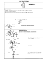
Installation ........................................................... 3
Features and Operation....................................... 7
Accessory Installation .......................................... 8
Troubleshooting ................................................. 14
Wiring Diagram .................................................. 15
Maintenance ...................................................... 16
Technical Service............................................... 23
Replacement Parts ............................................ 23
Parts .................................................................. 24
Accessories ....................................................... 27
Warranty ..............................................Back Cover
WARNING: Electrical wiring
must comply with local build-
ing codes and other applicable
regulations to reduce the risk of
re, electrical shock and injury
to persons.
WARNING: Do not use this
replace if any part of it has
been under water. Immediately
call a qualied service techni-
cian to inspect the replace and
replace any part of the electrical
system.
CAUTION: Extreme caution
is necessary when any heater is
used by or near children or inva-
lids and whenever the heater is
left operating and unattended.
1. Read all instructions before using this
replace.
2. This replace is hot when in use. To avoid
burns, do not let bare skin touch hot sur-
faces. If provided, use handles when ac-
cessing replace controls. Keep combus-
tible materials, such as furniture, pillows,
bedding, papers, clothes, and curtains at
least 3 feet from front of replace.
3. Extreme caution is necessary when any
heater is used by or near children or inva-
lids and whenever heater is left operating
and unattended.
4. Always place main power switch in OFF
position when not in use.
5. Do not operate replace if any part has
been damaged or is malfunctioning.
6. Any repairs to this replace should be
done by a qualied service person.
7. Do not use outdoors.
8. This replace is approved for installation
in bedrooms.
9. Under no circumstances should this
replace be modied. Parts having to be
removed for servicing must be replaced
prior to operating this replace.
10. This replace is not intended for use in
bathrooms, laundry areas and similar
locations where it would be subject to
excessive moisture.
11. This replace may not be installed out-
doors or in an unenclosed space where
exposed to the elements.
12. To disconnect this replace, turn off at
circuit breaker or fuse panel.
13. This appliance, must be electrically
grounded in accordance with local codes
and the National Electric Code, ANSI/
NFPA No. 70 or in Canada with CSA
C22.1 Canadian Electrical code.
14. Do not insert or allow foreign objects to
enter any ventilation or exhaust openings.
This may cause an electrical shock, re
or damage to replace.
15. To prevent a possible re do not block air
intakes or exhaust.
16. This fireplace has hot and arcing or
sparking parts inside. Do not use in areas
where gasoline, paint or ammable liquids
are used or stored. This replace should
not be used to dry clothing or for hanging
decorations.
17. Use this replace only as described. Any
other use not recommended by the manu-
facturer may cause re, electric shock or
injury to persons.
18. SAVE THESE INSTRUCTIONS.
www.desatech.com
111076-01F 3
PRODUCT SPECIFICATION
E32 = 15
5
/
8
"
E36 = 17"
E32 = 16
1
/
4
"
E36 = 17
5
/
8
"
E32 = 22
1
/
4
"
E36 = 24
1
/
4
"
E32 = 29
3
/
8
"
E36 = 35"
E32 = 7"
E36 = 8"
E32 = 6
1
/
2
"
E36 = 5
1
/
4
"
E32 = 18
3
/
8
"
E36 = 21"
E32 = 33
3
/
8
"
E36 = 37"
E32 = 36
3
/
8
"
E36 = 43"
E32 = 35
3
/
8
"
E36 = 42"
E32 = 34
5
/
8
"
E36 = 41
1
/
4
"
E32 = 32
5
/
8
"
E36 = 36
1
/
4
"
E32 = 28
3
/
8
"
E36 = 31
3
/
4
"
E32 = 32
7
/
8
"
E36 = 36
1
/
2
"
1
7
/
8
"
5/8"
TOP
FRONT
LEFT SIDE RIGHT SIDE
E32 = 32
1
/
8
"
E36 = 36
1
/
8
"
E32 = 28
3
/
8
"
E36 = 31
3
/
4
"
To Nail
Location
To Nail
Location
E32 = 8"
E36 = 5
1
/
4
"
ELECTRICAL SPECIFICATIONS
Voltage: 120 VAC, 60 Hz
Total Amps: 12.5 Amps
Total Watts: 1500 Watts
Heater Rating: 1100 Watts
Max. Bulb Rating: 100 Watts
Use only on 15 amp circuit
Figure 1 - Unit Dimensions
INSTALLATION
LOCATING FIREPLACE
Plan where to locate and frame replace.
Before installation consider the following:
1. Fireplace location must allow for wall and
ceiling clearances (see Installation Clear-
ances, page 4).
2. Fireplace screen should not be exposed
to direct sunlight from windows or doors.
3. A 15 amp, 120 Volt, 60 Hz circuit with
proper ground must be available. A dedi-
cated circuit should be provided to avoid
circuit breaker trips or blown fuses.
Flush Installations are recommended where
living space is limited or at a premium. Since
space required to enclose replace would
be located beyond an outside wall, this in-
stallation would require additional planning
and construction. Check local codes for any
restrictions.
Figure 2 - Possible Installation Locations
Internal Wall
Installation
Full Projection
Installation
Flush
Installation
Corner
Installation
Projected Installations can extend any dis-
tance into room. A projection may be ideal for
a new addition on an existing, nished wall.
Corner Installations make use of space
that may not normally be used and provides
a wider and more efcient viewing angle and
heat distribution.
Internal Wall Installations provide a discrete
option for room separation and can also be an
ideal addition to an existing wall.
www.desatech.com
111076-01F4
INSTALLATION CLEARANCES
Minimum clearances to combustible construction are:
Top, Back and Sides of Recessed
Cabinet . . . . . . . . . . . . . . . . . . . . .0" Min.
Drywall to Sides of Front Face . . .0" Min.
Framing at Nailing Flanges . . . . . .0" Min.
Ceiling to Opening . . . . . . . . . . . .36" Min.
Facing Material May
Be Noncombustible
Wall Treatments or
Combustible Wood
Combustible Wood
Mantels and Trims
May Extend Above
Profile Shown when
Maintained within
30° Parameter
Shown
Framed
Material
Top of Cabinet
Note: All Mantel Clearances
are Measured from Top of
Fireplace Opening
30°
16
5
/
8
"
Ref.
9
5
/
8
" Ref.
12" Ref.
13
3
/
4
"
4
1
/
2
"
1
1
/
2
"
1
3
/
4
"
10
1
/
2
" Min.
10
1
/
2
"
Figure 3 - Mantel Clearances
Top View of Fireplace
Safe Zone
5"
3"
30°
1
3
/
4
" Max.
Minimum 10" from
Perpendicular Side Wall
Edge of Firebox
Opening
Combustible
MaterialMust
Not Overlap
Front Face
Figure 4 - Mantel Side Clearances
INSTALLATION
Continued
Floor . . . . . . . . . . . . . . . . . . . . . . .0" Min.
Front . . . . . . . . . . . . . . . . . . . . . .36" Min.
Perpendicular Side Wall . . . . . . .10" Min.
Mantel Clearances
For mantel clearances see Figures 3 and 4.
www.desatech.com
111076-01F 5
INSTALLATION
Continued
BUILT-IN INSTALLATION
Built-in installations require a framed enclo-
sure constructed of 2" x 4" or heavier lumber
and sized in accordance with Figure 5. This
allows unit to slide into opening and be nailed
to stud at sides and top nailing anges. These
anges accept 5/8" drywall or plywood board
to nish unit ush to face. Optional trim ac-
cessories are available that will extend 1/2"
over rough edge of wall opening (see Acces-
sories, page 25).
IMPORTANT: If installing a perimeter trim kit,
you must install shoulder screws before insert-
ing replace into opening. See instructions
included with trim kit. If installing a mantel,
you must follow clearance instructions (see
Installation Clearances, page 4).
A hearth extension is suggested for a more
pleasing appearance. The replace may be
raised on a wood or non-combustible platform
supporting its entire width and depth and
extending in front of the replace as long as
louvers are not obstructed.
Note: When installing replace in cold cli-
mates against a non-insulated exterior wall,
wall must be fully insulated in accordance with
local building code.
VE32 = 34
5
/
8
"
VE36 = 41
1
/
4
"
VE32 = 15
7
/
8
"
VE36 = 17
1
/
4
"
VE32 = 32
5
/
8
"
VE36 = 36
1
/
4
"
Platform/Subflooring
Figure 5 - Framing Dimensions
VE32 = 37
5
/
8
"
VE36 = 42
3
/
8
"
VE32 = 26
5
/
8
"
VE36 = 29
3
/
8
"
VE32 = 52
3
/
4
"
VE36 = 58
1
/
4
"
11
5
/
8
"
These Dimensions
Allow for 11
5
/
8
" of
Clearance to Side
Wall of Fireplace
and 10' Clearance
to Perpendicular
Side Walls
Figure 6 - Corner Dimensions
ELECTRICAL INSTALLATION
WARNING: Any electrical re-
wiring of this appliance must be
done by a qualied electrician.
This wiring must be done in ac-
cordance with local codes and/or
in the U.S.A. with the current, Na-
tional Electrical Code ANSI/NFPA
No 70 and in Canada with CSA
C22.1 Canadian Electric code.
This replace should be con-
nected to a dedicated 15 Amp,
circuit as other appliances may
cause the circuit breaker to trip
or fuse to blow when replace
is in operation.
A junction box with universal strain adaptor is
provided to hard wire unit to a 15 amp, 120
Volt 60 Hz grounded circuit. If necessary,
junction box may be relocated to route sup-
ply to left side.
1. Remove 2 screws and outer cover on right
side (see Figure 7, page 6).
2. Remove inner screw securing junction
box.
3. Slide junction box up until mounting tab
is lined up to notch in outer cabinet.
4. Swing box out and slip retaining ange
out through slot in outer cabinet.
5. Remove 2 screws and outer cover on left
side and reattach on right side of outer
cabinet.
www.desatech.com
111076-01F6
6. Swing junction box with harness to left
side while pulling sufcient length of har-
ness out through control panel cover to
reach mounting location on left side.
7. Reinsert retaining ange through slot and
swing screw mounting tab back through
notch as before.
8. Slide junction box down until mounting
holes line up and replace inner retaining
cover.
9. Pull end of 3 wire Romex supply line
through universal strain relief bushing in
remaining cover.
10. Strip back outer Romex to about 4” and
connect black, white and green wires ac-
cordingly using approved connectors.
Screws
and
Outer
Cover
Junction Box
Mounting
Tab
Notch
Retaining
Flange
Slot
Screws and
Outer Cover
from Other Side
Cover with
Universal
Strain Relief
Figure 7 - Relocating Junction Box to
Left
INSTALLATION
Continued
Junction Box
Figure 8 - Removing Shipping Brace
Foam
Shipping
Brace
Motor
Mount
11. Tuck tailing wires into junction box and
replace cover using 2 remaining screws.
12. Tighten down strain adjustment on uni-
versal bushing until Romex sheathing is
secured.
IMPORTANT: Inspect components and wir-
ing for damage before connecting power to
unit. If any components are found damaged,
contact an authorized dealer for original DESA
Heating Products replacement part(s) or call
DESA Heating Products at 1-866-872-6040
for referral.
IMPORTANT: Prior to operation remove foam
shipping brace located under motor mount
(see Figure 8).
www.desatech.com
111076-01F 7
INSTALLATION
Continued
LAMPS AND LAVA ROCK
Before operating replace, lamp bulbs must
be inspected and lava rock may be added if
desired.
1. Lift log bed off hearth base to gain access
to lamp xtures (log bed is attached with
contact magnets).
2. Turn on power to light circuit and check
that all bulbs are operating. Bulb place-
ment front left to right are red, yellow and
orange (see Figure 9).
Note: If bulbs need replacing, see Replac-
ing Light Bulbs, page 16. Be careful not to
tear or damage reective strips. If they have
come loose, ends can be easily reattached or
replaced at support brackets. See Replacing
Reective Ribbons, page 21.
FEATURES AND OPERATION
Figure 9 - Bulb Placement
Red
Yellow
Orange
Log Bed
Figure 10 - Accessing Controls
Grate
Viewing Panel
Screen
3. Center log bed over opening between
viewing panel screen and grate.
4. Cover remaining hearth area with 1/4" of
lava rock (provided), if desired.
This electronic fireplace series features
a random ame effect, and a realistic log
bed with glistening embers that can be ad-
justed for ame speed and light intensity.
E36/32LH models have a circulating heater,
rated at 1100 Watts. Models E36/32LB and
E36/32LBH include a hand detailed, textured,
red-brick lining.
Access controls by pulling two handle tabs
of upper louver until panel releases from
magnetic catches and swings down to open
position (see Figure 10).
Figure 11, page 8, shows control layout for
heater equipped models with main power
switch to ame controls and heater power
switch (when equipped) to heating unit. This
allows independent and efcient operation of
both features.
Once main power is turned on, ame speed
and brightness may be turned on and adjusted
independently.
www.desatech.com
111076-01F8
ACCESSORY INSTALLATION
FEATURES AND OPERATION
Continued
Figure 11 - Control Panel
Figure 12 - Installing/Removing Glass
Doors
Spring Clip
Depress Spring
Clip to Release
Pivot Pin
Remove Pivot Pin
From Bottom Face
While Sliding Door
Out of Upper Track
Pivot Pin
Fold Bifold Door
After Releasing
Spring Clip to
Slide Door Out of
Upper Track
Figure 13 - Adjust Glass Door
Spring Clip
Partially
Opened
Door
Side Front
Face
LOWLOW
MAIN
POWER
HI- OFF
FLAME SPEED
HI- OFF
FLAME BRIGHTNESS
HEATER
ON/OFF
Switch
Flame Brightness
Flame Speed
Heater Switch
OPTIONAL GLASS DOORS
Models E36L and E32L will accept bifold glass
doors that are fully operable or a xed panel
door that limits access to replace, (see Ac-
cessories, page 25).
Installing Bifold Glass Doors
Follow these steps to install left and right
operable panels:
1. With handle down, completely fold panel
on its hinges.
2. With handle facing center of rebox open-
ing insert lower pivot pin on door panel
into hole in bottom outer edge of rebox
opening (see Figure 12).
3. Keep folded door tilted and slide upper two
pins into guide track below upper facial
edge of rebox opening.
4. Tilt glass assembly fully vertical until outer
pivot pin snaps into mounting hole in up-
per spring clip.
5. Once top and bottom pins are secured,
unfold door into closed position.
6. Repeat steps 1 through 5 for opposite
door assembly.
7. To adjust doors, slide partially open.
Using a Phillips screwdriver, loosen hold-
down screws on spring clips (see Figure
13).
8. Close both doors until evenly joined at
middle and note gap as measured to outer
edges of front face.
9. Reopen each door one at a time and
retighten the hold-down screw while pre-
serving noted gap at each edge.
10. Repeat process until both doors are even-
ly joined, spaced and working freely.
www.desatech.com
111076-01F 9
Removing Bifold Glass Doors
Bifold doors may be removed for replacing
or cleaning.
1. Partially open each door and press up on
upper spring clip with a screw driver until
outer top pivot pin is free of the clip.
2. Fully fold frame assembly and slide upper
edge towards center of rebox opening
until the guide pins are free of the frame
rail (see Figure 12, page 8).
Installing Series Fixed Glass Doors
1. Hold glass door rmly at both handles and
insert top pins into clips located below up-
per facial edge of rebox opening. Make
sure top pins snap securely into holes on
spring clips (see Figure 14).
2. Push up on glass against tension of spring
clips. Swing lower door into face until lower
pins clear bottom rail and set into locating
holes on each end (see Figure 14).
Note: If pins do not align into spring clips,
slightly loosen retaining screws on each clip
(see Figure 13, page 8). Reinsert panel into
each spring clip and align panel into lower
locating holes. Remove panel, nish tighten
screws and reinsert panel.
ACCESSORY INSTALLATION
Continued
Figure 14 - Installing Fixed Glass Doors
Spring Clip
Locating
Hole
OPTIONAL BRICK LINERS
Installing or Removing Brick Liner Kits
Brick liner kits are available for Models
E36/32(L)(H) (see Accessories, page 25).
These brick panels may be installed anytime
after replace installation is complete.
Follow these steps to install left and right
brick panels:
1. Remove glass doors (if equipped). Follow
instructions under Optional Glass Doors,
page 8.
2. Remove each retaining screw holding
screen rods and pull entire screen and rod
assembly out of locating hole on inside top
edge of rebox (see Figure 15).
3. Remove log bed from hearth pan and
place in a safe area. Log bed is attached
with contact magnets only.
4. Remove two screws holding each refrac-
tory bracket to rebox. Pull up and lift out
of positioning slot at bottom of hearth pan
(see Figure 16, page 10).
Note: E36L and E36LH models require
removal of additional hearth brackets and
face panels which are held in place by 2
screws on hearth pan and one screw at top
retainer bracket (see Figure 16, page 10).
Figure 15 - Removing Screen/Rod
Assembly
Screen
Rod
Retaining
Screw
Mounting
Holes
www.desatech.com
111076-01F10
ACCESSORY INSTALLATION
Continued
5. Insert brick panel, beveled edge first,
through rebox opening. Tilt and angle top
edge into brick retainer until beveled edge
contacts imager and panel is at against
rebox (see Figure 17).
6. Align hearth pan bracket over holes near
lower edge of brick panel and secure with
2 pan screws provided.
7. Replace refractory bracket using 2 screws
removed in step 4, page 9.
8. Repeat steps 5 through 7 for opposite
panel assembly.
9. Replace each screen assembly by po-
sitioning screen rod into locating holes
under top edge of rebox and securing
with 2 Phillips screws removed in step 2,
page 9.
Note: Rods may have to be angled into
locating holes at the top of each screen
pocket. Once inserted, pull free end of rod
forward until it lines up over farthest mount-
ing hole respectively so rods overlap.
10. Replace log bed over hearth opening
and center between grate and viewing
screen.
11. Replace glass doors if removed. See
Optional Glass Doors, page 8.
OPTIONAL HEATER ACCESSORY
WARNING: Disconnect
power before attempting any
maintenance or cleaning to re-
duce the risk of re, electrical
shock or personal injury.
Blower/heater kit model BHKE is available
for models E36/32L and E36/32LB. Either
of 2 types of blower/heater assemblies can
be installed.
1. Open upper control door (see Figure 10,
on page 7) and remove 2 Phillips screws
below heater grill on control panel (see
Figure 18, page 11).
2. Remove 2 Phillips screws holding control
cover to control panel inside rebox (see
Figure 14, page 9).
3. Slide control cover to the right and swing
out locking tabs from notched openings
on top (see Figure 18, page 11).
4. Let control cover hang down off har-
nesses. Be careful not to damage any
wiring. If necessary, unscrew harness
strap at blower mount to gain slack.
5. Remove 2 hex screws at rear of blower
mount (see Figure 18, page 11).
Figure 16 - Removing Refractory Bracket
and Hearth Pan Bracket
Face Panel
(Models E36L
and E36LH
Only)
Hearth Pan Bracket
(Models E36L and
E36LH Only)
Refractory
Bracket
Figure 17 - Installing Brick Panels and
Brackets
Refractory
Retainer
Bracket
Hearth Pan
Bracket
Refractory
Bracket
www.desatech.com
111076-01F 11
ACCESSORY INSTALLATION
Continued
6. Slide blower mount towards rear of rebox
until locking tabs line up with notched
openings and lower mount down and
away (see Figure 18).
7. Remove blower/heater assembly with 4
screws from packaging. Blower is pre-
wired for convenience.
8. Align blower assembly over hole pattern on
blower mount and attach with 4 pan head
screws provided (see Figures 19 and 20).
9. With discharge pointing towards you, guide
assembled blower mount into replace
and center rear mounting anges between
standoff brackets at rear of the replace.
10. Lift blower mount up and position 4 locking
tabs through notched openings in rebox
top. Slide assembly forward until locked
into position.
11. Remove control panel knockout plug lo-
cated in heater switch position by pressing
locking tabs and pushing plug out through
front of panel (see Figure 21).
12. Firmly insert red power switch into open
mount location with ON (I) indicator
positioned on top.
Figure 18 - Disassembling Blower Mount
Control
Panel
Control
Cover
Blower
Mount
Control
Cover
Screws
Hex
Screws
Notches for Control Cover
Blower Mount
Notch (1 of 4)
Screws
Figure 19 - Mounting Heater/Blower
Figure 20 - Mounting Alternate Heater/
Blower
Harness
Strap
Heater/
Blower
Assembly
Blower
Mount
Mounting
Screws
Mounting
Screws
Heater/
Blower
Assembly
Blower
Mount
Figure 21 - Installing Heater Power Switch
Knockout Plug
Remove to
Install Power
Switch
Power
Switch
www.desatech.com
111076-01F12
ACCESSORY INSTALLATION
Continued
13. Connect white heater wire to neutral con-
nection marked 'B' or 'A' on terminal block.
See partial wiring diagram, Figure 22.
14. Connect black heater wire to terminal
marked 'N-1' on heater power switch (see
Figure 23, page 13).
Note: On alternate style heaters white and
black wires are connected common to
terminal 'N-1' (see Figure 24, page 13).
15. Connect red heater wire to terminal
marked 'L-4' on heater power switch (see
Figure 23 or 24, page 13.
16. Connect one end of black jumper lead,
provided in kit, to power connection
marked 'D' on terminal block and other
end to switch terminal marked 'L-5' (see
Figure 25, page 13).
17. Replace 2 hex screws on rear anges of
blower mount removed in step 5, page 10.
18. Remount harness strap to blower mount,
if removed.
BLK
BLK
TERMINAL
WHT
BLK
GRN
BLK
D C
CONNECTION
SUPPLY
RED
RED
N 1
4 L
5 L
HEATER
COIL
AB
HEATER
POWER
MOTOR
WHT
CUTOUT
WHT
WHT
WIRES TO HEATER CIRCUIT
WHT - ALTERNATE
BLK
HARNESS 4" BLK
Figure 22 - Heater Circuit Diagrams
19. Make sure all wires are clear of heater
discharge area, line up mounting holes on
front blower mount to holes in control panels
and replace the 2 black pan head screws.
20. Raise control cover up and position 2
locking tabs through notched openings in
rebox top, then slide to left until locked
into position (see Figure 18, page 11).
21. Tuck any excess slack in harnesses into
control cover. Swing cover down to line
up mounting holes on control panel and
replace 2 Phillips screws removed in
step 2, page 10.
22. Restore power to unit and check operation
of the heater.
IMPORTANT: Be sure to inspect components
and wiring for damage before connecting
power to unit. If any components are found
damaged, contact an authorized dealer for
original DESA Heating Products replacement
parts(s) or call DESA Heating Products at
1-866-872-6040 for referral.
www.desatech.com
111076-01F 13
Rocker
Switch
Red (L-4)
Black (N-1)
Heater/Blower
White (A-B)
Terminal Block
Figure 23 - Connecting Heater Wires
Figure 25 - Connecting Jumper Lead
Switch
Terminal (L-5)
ACCESSORY INSTALLATION
Continued
White (N-1)
Red (L-4)
Rocker
Switch
Heater/Blower
White (A-B)
Terminal Block
Figure 24 - Connecting Alternate Heater Wires
Jumper
Lead
Terminal (D)
www.desatech.com
111076-01F14
TROUBLESHOOTING
Note: Before troubleshooting system, make sure power to circuit from breaker or fuse panel
is turned ON.
The three most common causes of a malfunctioning electric replace are:
1. Tripped circuit breaker or blown fuse.
2. Loose or burned out light bulb.
3. Obstructed or clogged fan blower.
POSSIBLE CAUSE
1. No power to replace
2. Defective switch lamp
3. Defective wiring
1. Tangled or loose flame
pennants
2. Obstructed or clogged fan
blower
3. Damaged or dislodged fan
blower wheel
1. Burned out or loose light
bulb
2. Broken lamp xture
3. Loose or missing reective
ribbons
1. Obstructed heater blower
2. Burned out heat element
or blower fan
3. Defective heater switch or
wiring
REMEDY
1.
Check circuit breaker or fuse
2. Replace defective switch.
See Servicing Control Pan-
el, page 17
3. Check connections from
main power harnesses to
terminals on control panel.
See Servicing Control Pan-
el, page 17
1. Inspect ame pennants. Un-
tangle or replace if neces-
sary. See Servicing Flame
Pennants, page 19
2. Check fan blower for de-
bris. Vacuum areas around
blower wheel and remove
any obstructions. See Main-
taining Motors, page 16
3. Remove and inspect fan
blower housing See Servic-
ing Fan Blower, page 19
1. Inspect light bulbs; tighten
or replace light bulbs as
necessary. See Replacing
Light Bulbs, page 16
2. Remove and replace broken
lamp xture. See Replacing
Lamp Fixtures, page 20
3. Inspect reective ribbons.
Reattach or replace as nec-
essary. See Replacing Re-
ective Ribbons, page 20
1.
Clear heater fan of debris
or blockage; vacuum area
around blower intake and
remove any obstructions
in the discharge area. See
Maintaining Motors, page 16
2. Remove and replace blower
heater assembly. To access
and remove see Optional
Heater Accessory, page
10
3. Inspect wiring connections
from switch to blower. Re-
place switch if defective.
See Servicing Control Pan-
el, page 17
OBSERVED PROBLEM
No operation or indicator light
at power/heater switch
Poor ame motion; ame pat-
tern is sporadic or uneven in
viewing area
Dull ame appearance or inac-
tive ember bed effect
No heat or intermittent heat
output. (If equipped with a
heater)
www.desatech.com
111076-01F 15
WIRING DIAGRAM
YELLOW LAMP
WHT
HARNESS 4" BLK
HEATER
POWER
FRONT HARNESS TO LAMP CIRCUIT
RED LAMP
SPLICE CONNECTION
MALE CONNECTION
FEMALE CONNECTION
GRN
BLK
WHT
BLK
SUPPLY
ORANGE LAMP
FAN MOTOR
FLAME PROJECTOR - ELECTRICAL DIAGRAM
WHT
BLK
CONTROL PANEL - ELECTRICAL DIAGRAM
BLK
HARNESS 24"
WHT
BLK
GRN
GRN
WHT
FLAME
CONTROL
TERMINAL
CD AB
BLK
5 L
4 L
N 1
BLK
GRN
BLK
FAN
CONTROL
CD B
TERMINAL
HARNESS 4" BLK
REAR HARNESS TO
MOTOR CIRCUIT
BLK
BLK
BLK
A
WHT
5 L
BLACK
BLK
4 L
N 1
MAIN
HEATER ASSEMBLY - ELECTRICAL DIAGRAM
HEATER
COIL
RED
RED
BLK
BLK
MOTOR
CUTOUT
WHT
CAUTION: USE SUPPLY WIRES SUITABLE FOR 105°C OR EQUIVALENT
CAUTION: DISCONNECT FIREPLACE FROM THE ELECTRICAL SUPPLY
BEFORE REMOVING THIS COVER
POWER
CONNECTION
HARNESS
4" WHT
BLK
WHT
BLK
WHT
WHT - ALTERNATE
CIRCUIT
Figure 26 - Wiring Diagram
www.desatech.com
111076-01F16
MAINTENANCE
WARNING: Disconnect
power before attempting any
maintenance or cleaning to re-
duce the risk of re, electrical
shock or personal injury.
WARNING: Any electrical
repairs or rewiring of this unit
should be carried out by a li-
censed electrician in accordance
with national and local codes.
WARNING: Do not exceed
60 watts per bulb when replac-
ing bulbs. Use of higher-rated
bulbs may result in a re, caus-
ing property damage, personal
injury, or loss of life.
REPLACING LIGHT BULBS
There are (3) colored lamps rated at 120V,
60 Watts, for use in a medium sized socket.
These bulbs are located under the log bed
and can be replaced as follows:
1. If you are unsure which bulb needs re-
placement, defective bulbs may be visually
located as any of 3 bulbs colored - Red,
Yellow and Orange starting from the left
(see Figure 9, page 7). Defective bulbs can
be replaced individually or for convenience
you may want to replace all bulbs at the
same time; even if only one is defective.
2. Disconnect power to unit at main breaker
or fuse panel.
3. Lift log bed off hearth base to gain access
to lamp xtures. Log bed is attached with
contact magnets only.
4. Remove each defective bulb from its
socket and replace with appropriate color
and size bulb.
Note: Be careful not to tear or damage reec-
tive ribbons. If they have come loose, they
can be easily reattached or replaced at the
support brackets. See Replacing Reective
Ribbons, page 21.
5. Return power to circuit and turn main power
switch and lamp power on to check opera-
tion of bulbs before replacing log set.
Figure 27 - Removing/Replacing Control
Door
Deector
Shield
Control
Door
Magnet
Assembly
Push
Door Up
and
Back
Angle
Door and
Slide
Out of
Housing.
6. If all bulbs are working properly, replace
log bed over center opening between rear
screen and front grate.
CAUTION: Make sure power
is turned off at supply prior to
disassembling this unit.
MAINTAINING MOTORS
Motors used on fan and heater assembly
are permanently lubricated and do not
require lubrication. Annual cleaning and/or
vacuuming around heater and fan unit is
recommended.
REMOVING/REPLACING CONTROL
DOOR
Upper control door may be removed for ser-
vice or replacement when necessary:
1. Open upper control door (see Figure 10,
page 7).
2. Remove 4 Phillips screws from deector
shield. Angle deector shield out of open-
ing (see Figure 27).
3. Remove 4 Phillips screws from magnet
assemblies.
4. Lift up on inner control door and push
in each end until pivot pins are free of
notches located on each side of access
opening (see Figure 27).
www.desatech.com
111076-01F 17
5. Rotate control door up into control com-
partment and slide on end into side of
compartment.
6. Tilt out one end rst then pull remaining
door assembly through opening.
7. Replace door, by starting with door upside
down, pins up and facing unit. Follow step
5 in reverse until pins are rmly set back
in notches and door will close.
8. Replace discharge deector and magnet
assemblies.
SERVICING CONTROL PANEL
Control panel can be serviced from inside
unit by removing rear control cover on inside
of rebox. Follow steps 2 through 4 under
Optional Heater Accessory, page 10.
If control assembly needs complete replace-
ment, proceed to remove entire control as-
sembly as follows:
1. Remove glass doors (if equipped). Follow
instructions under Optional Glass Doors,
page 8.
2. Remove each retaining screw holding
screen rods and pull entire screen and
rod assembly out from locating hole on
inside top edge of replace (see Figure
18, page 11).
3. Remove log bed from hearth pan and
place in a safe area. Log bed is attached
with contact magnets only. This step is
included to keep logs from being damaged
during panel replacement.
4. Remove 2 Phillips screws holding control
cover to control panel inside rebox (see
Figure 18, page 11).
5. Slide control cover right and swing out
locking tabs from notched openings on
top. See detail Figure 18, page 11.
6. Pop out bushings on control cover and slip
power harnesses free from control cover
(see Figure 28).
7. Remove magnet assemblies, deector
shield and control door. See Removing/
Replacing Control Door, page 16.
8. Remove 4 screws from control panel (see
Figure 29). Tilt entire control assembly
forward to clear lower ange at upper
door rail and slide assembly down through
space between front face and firebox
mount (see detail Figure 30).
9. Angle control panel out through opening
(see Figure 30).
10. Follow these instructions in reverse order
to reassemble control panel assembly.
Note: Be certain that all wires, harnesses and
bushings are returned to their normal position
and free of damage before reconnecting sup-
ply power to the replace.
CAUTION: Note location of
all wires prior to disconnecting.
Be sure to reconnect wires to
their proper locations. If you
are unsure about proper wire
locations, follow wiring diagram
Figure 26, on page 15.
MAINTENANCE
Continued
Figure 28 - Detaching Power Harnesses
LOWLOW
MAIN
POWER
FLAME SPEED FLAME BRIGHTNESS
HEATER
Panel Screws
Figure 29 - Panel Screws Location
Figure 30 - Removing Control Panel
Control
Panel
Power
Harnesses
Bushings
Control
Cover
www.desatech.com
111076-01F18
ACCESSING IMAGING UNIT
Imaging unit can be accessed from inside
replace for servicing as follows:
1. Remove glass doors (if equipped). See
Optional Glass Doors, on page 8.
2. Remove screens, grate, hearth pan brack-
ets and brick liners. See Figure 31 and
instructions under Optional Brick Liners,
page 9.
3. Remove 4 Phillips screws holding hearth
pan to replace and 2 screws located at
lower frame rail (see Figure 32).
4. Lift rear ends of hearth pan up until front
edge clears lower frame rail then slide
up on end and angle out of replace
opening.
5. Remove 4 Phillips screws holding face
extensions at top refractory clips (see
Figure 32).
6. Remove viewing screen from cabinet
face. Viewing screen is attached by mag-
nets (see Figure 33).
Note: Do not scratch viewing screen. Place
on a nonabrasive surface away from work
area. When replacing viewing screen painted
side must face inside of cabinet with pattern
facing up.
MAINTENANCE
Continued
Figure 31 - Accessing Imaging Unit
Refractory
Brackets
Grate
Hearth Pan
Bracket
Hearth Pan
Bracket
Brick Liner
Brick
Liner
Figure 32 - Removing Hearth Pan and
Face Extensions (Extensions for E32
Series Only)
Hearth Pan
Face Extensions
Refractory Clip
Viewing Screen
Figure 33 - Removing Viewing Screen
7. Remove 4 Phillips screws on base cover
and lift cover off cabinet base. See Figure
34, page 19.
Note: Only E32 series models have face
extensions that require removal to access
imaging unit. Model E36 series has inner face
panels that also require removal to access
imaging unit.
www.desatech.com
111076-01F 19
SERVICING FAN BLOWER
To remove fan blower:
1. Follow instructions under Accessing Imag-
ing Unit, page 18.
2. Remove 3 light bulbs from lamp xtures
(see Replacing Light Bulbs, page 16).
3. Disconnect two 1/4" blade connectors at
from posts on motor unit.
4. Remove 4 hex nuts and washers located
on blower mounts at base of cabinet (see
Figure 35).
5. Lift entire fan assembly off of mounts and
tilt out of unit.
6. Remove screws with washers and hex
nuts from fan housing.
7. Mount new fan to blower mount in reverse
order.
8. Slide blower assembly with spacers over
mounting lugs and replace washer and
nut at each lug. Do not over tighten.
9. Attach blade connectors to posts on motor
mount.
Note: Wire connectors for fan motor are
non-polarized and may be connected to
either terminal for proper operation.
SERVICING FLAME PENNANTS
If ame pennants should become tangled or
detached reattach or replace.
1. Locate affected ame pennant. Slip hem
at base of ame pennant over proper
hanger bracket position. See Figure 36,
page 20, for proper location.
2. Pull ame cord up to proper hook location,
use a slip knot to adjust cord length and
attach cord to hook.
3. Tie another knot over slip knot and trim
away excess cord.
MAINTENANCE
Continued
Figure 34 - Removing Base Cover
Base
Cover
Figure 35 - Removing Fan Assembly (Shown without Firebox for Clarity)
Washer
Hex Nut
Fan Assembly
Blower
Mount
(1 of 4)
Washer
Hex
Nut
Screw
Spacer
Posts for Blade
Connectors
www.desatech.com
111076-01F20
8"
7"
3
1
/
2
"
1
1
/
2
"
Figure 36 - Locating Flame Pennants
Flame Cord
Flame
Pennant
Flame
Spacer
MAINTENANCE
Continued
Note: Flame pennant should not be twisted
or tangled and should hang slightly loose to
allow free movement. If cord is too short or
pennant is torn you must obtain a replacement
ame assembly (see Replacement Parts, on
page 23).
Hook
4. After connecting and adjusting flame
cords, soak each knot with a drop of white
wood glue or clear nail polish to prevent
unraveling.
REPLACING LAMP FIXTURES
Lamp xtures may be replaced as follows:
1. Turn off all power to replace at circuit
breaker or fuse.
2. Locate any of 3 defective lamp xtures
and trace wiring to crimp connectors in
harness and disconnect.
3. Remove 2 crimp connectors in harness
and disconnect white and black wires on
defective xture. See Wiring Diagram, Fig-
ure 26 on page 15, for proper locations.
4. Remove 2 Phillips screws at base of de-
fective xture (see Figure 37, page 21).
5. Remove old xture and mount new xture
with 2 Phillips screws removed prior.
6. Twist bare ends of white and black wires
to corresponding wires in main harness
and secure them with 2 crimp connectors
provided.
Note: There should be no exposed bare
wire at any connection. Wiring should be
secured with wire ties, as short as possible,
and kept away from fan blades. If additional
parts are required, see Replacement Parts,
on page 23.
  • Page 1 1
  • Page 2 2
  • Page 3 3
  • Page 4 4
  • Page 5 5
  • Page 6 6
  • Page 7 7
  • Page 8 8
  • Page 9 9
  • Page 10 10
  • Page 11 11
  • Page 12 12
  • Page 13 13
  • Page 14 14
  • Page 15 15
  • Page 16 16
  • Page 17 17
  • Page 18 18
  • Page 19 19
  • Page 20 20
  • Page 21 21
  • Page 22 22
  • Page 23 23
  • Page 24 24
  • Page 25 25
  • Page 26 26
  • Page 27 27
  • Page 28 28

Desa E32L User manual

Category
Fireplaces
Type
User manual

Ask a question and I''ll find the answer in the document

Finding information in a document is now easier with AI