Danfoss H1 P User guide

Type
User guide

Danfoss H1 P is a high-performance axial piston variable displacement pump designed for use in closed circuit applications. With its compact design and high power density, it provides precise control over hydraulic flow rate and direction. The pump is compatible with Danfoss PLUS+1 microcontrollers for easy installation and operation. This pump excels in applications requiring proportional flow control, such as mobile machinery, industrial equipment, and marine vessels. Its versatility makes it suitable for a wide range of hydraulic systems, enabling efficient and reliable performance.

Danfoss H1 P is a high-performance axial piston variable displacement pump designed for use in closed circuit applications. With its compact design and high power density, it provides precise control over hydraulic flow rate and direction. The pump is compatible with Danfoss PLUS+1 microcontrollers for easy installation and operation. This pump excels in applications requiring proportional flow control, such as mobile machinery, industrial equipment, and marine vessels. Its versatility makes it suitable for a wide range of hydraulic systems, enabling efficient and reliable performance.

MAKING MODERN LIVING POSSIBLE
Functional Safety
Product Reliability Data (MTTF) for
H1P069-250
powersolutions.danfoss.com
Revision history Table of revisions
Date Changed Rev
May 2015 Added CCO information CB
April 2014 Danfoss layout CA
May 2013 Revise Functions - EC1035798 B
August 2012 First edition - EC1014364 A
Functional Safety H1 Pumps 069-250 Product Reliability Data
2 70086000 • Rev CBMay 2015
Overview
Approvals............................................................................................................................................................................................ 4
Danfoss Component
H1 Pumps............................................................................................................................................................................................ 5
Intended Use......................................................................................................................................................................................5
Introduction........................................................................................................................................................................................5
Results...................................................................................................................................................................................................5
Mission Time.......................................................................................................................................................................................6
Standards and Assumptions
Standards and Assumptions.........................................................................................................................................................7
Component Information and Calculations
F1: Safe Controllability (Pump at Demanded Displacement)...........................................................................................8
F2: Safe Stop (Pump to Neutral)..................................................................................................................................................9
F3: Prevent Unexpected Movement..........................................................................................................................................9
F4: CCO Function............................................................................................................................................................................10
F5: Safe Start.................................................................................................................................................................................... 10
F6: Safe/Correct Direction of Rotation/Movement (Hydraulic Motor/Cylinder).....................................................11
References
List of References........................................................................................................................................................................... 12
Functional Safety H1 Pumps 069-250 Product Reliability Data
Contents
70086000 • Rev CBMay 2015 3
This MTTF data has been compiled by the engineering team responsible for this product. These are
professionals at Danfoss, who have the authority and technical knowledge to calculate the MTTF Data for
this product based on the standards set in place by both the industry and/or Danfoss.
The purpose of this document is to assist in the transfer of MTTF information for the given product from
Danfoss to the appropriate party in a way which will result in a clear understanding and documentation
on how we derived it. This MTTF information is provided to assist in calculating the overall MTTF of a
complete or partially complete piece of machinery.
Danfoss cannot be held responsible for the suitability of these calculated MTTF values for use in the
calculation of the overall machinery MTTF values. The MTTF values for the pumps are based on a specific
machine use, operating environment, and/or duty cycle as stated by the standards set in place by both
the industry and/or Danfoss. This communication along with any attached Danfoss drawings, sketches, or
data is transmitted in confidence.
No information stated in this document or any attachments or supplements may be reproduced or
disclosed in whole or in part without written permission of Danfoss. Further, neither these documents
nor any attachments are a warranty of any sort by Danfoss or a guarantee of machine suitability for its
intended purpose. It remains the responsibility of the machine manufacturer to ensure overall machine
functionality and overall machine safety.
Approvals
List of Approvers
Name Title Date
1
2
3
Functional Safety H1 Pumps 069-250 Product Reliability Data
Overview
4 70086000 • Rev CBMay 2015
H1 Pumps
The H1 family of closed circuit variable displacement axial piston pumps is designed for use with all
existing Danfoss hydraulic motors for the control and transfer of hydraulic power. H1 pumps are compact
and high power density where all units utilize an integral electro-hydraulic servo piston assembly that
controls the rate (speed) and direction of the hydraulic flow. H1 pumps are specifically compatible with
the Danfoss family of PLUS+1 microcontrollers for easy Plug-and-Perform installation.
H1 pumps can be used together in combination with other Danfoss pumps and motors in the overall
hydraulic system. Danfoss hydrostatic products are designed with many different displacement, pressure
and load-life capabilities. Go to the Danfoss Power Solutions website or applicable product catalog to
choose the components that are right for your complete closed circuit hydraulic system.
Intended Use
The H1 axial piston variable displacement pumps are of cradle swash plate design and are intended for
closed circuit applications. The flow rate is proportional to the pump input speed and displacement. The
latter is infinitely adjustable between zero and maximum displacement. Flow direction is reversed by
tilting the swash plate to the opposite side of the neutral (zero displacement) position.
Details regarding intended use, such as application examples and operating conditions, are available in
Technical Information documents on our Danfoss Power Solutions web site:
http://www.powersolutions.danfoss.com/Products/PistonPumpsandMotors/
ClosedCircuitMediumPowerPumpsMotors/index.htm
For any intended use other than the above, contact your local Danfoss representative for advice.
Introduction
This technical report states the MTTF
d
for an H1 pump configuration. The pump configuration is
discriminated between a pump with feedback system and without a feedback system. The calculation of
the MTTF
d
values of each function is described in the attached document in Component Information and
Calculations chapter .
Results
The following table shows the MTTF
d
values of pump configurations and special functions.
Results of MTTF
d
on pump level
ID Pump Configuration MTTF
d
[years]
1 EDC Pump 150
2 NFPE, AC, FNR, FDC Pumps 150
3 CCO Function* 150
* no failures occured yet
Functional Safety
H1 Pumps 069-250 Product Reliability Data
Danfoss Component
70086000 • Rev CBMay 2015 5
Mission Time
Definition
Mission time represents the maximum period of time for which a subsystem (or system) can be used
After this time it must be replaced
The safety system designer must consider the mission time of the components to determine the
mission time of each safety function
The mission time of the above mentioned component is 20 years or will be otherwise explicitly stated
Functional Safety H1 Pumps 069-250 Product Reliability Data
Danfoss Component
6 70086000 • Rev CBMay 2015
Standards and Assumptions
The calculations are performed with reference to the Danfoss Global Standard GS-0078. The standard
GS-0078 defines the following options for how to determine the MTTF/MTTF
d
value for a specific
component or product. The process/algorithm selected will depend on:
Whether the component is purchased or manufactured
The availability of Danfoss field usage history
The availability of industry standard field usage history (primarily for electronic components)
Similarity of design to existing products
Knowledge of the design process
Some calculation options are listed below:
The methods outlined in ISO 13849-1 2006 Annexes C and D
Comparison to similar products already in production
Industry MTTF databases for widely available components (i.e. electronics)
MIL-HDBK-217
Siemens SN29500
Manufacturer’s Information
MTBF data from Verification testing in PDLP
Danfoss design practices and procedures for hardware and software design
Defects data from Danfoss CQAR database and/or customer data
Information on sold products originates from Danfoss SAP
Information on application profiles originates from Danfoss technical support knowledge
Functional Safety
H1 Pumps 069-250 Product Reliability Data
Standards and Assumptions
70086000 • Rev CBMay 2015 7
The following table lists the MTTF
d
for each individual pump function. Please consult your Danfoss
representative for further understanding of functions and the MTTF
d
values.
MTTF
d
for H1 Pumps
ID Function Specification/performance Input Output MTTF
d
[years]
F1 Provide controlled
output flow
See TI manual for specification/
performance of function
Current to
control
System flow
A/B
150
F2 Provide hydraulic
braking power
See TI manual for specification/
performance of function
Increased flow Seal increase
pressure
150
F3 No unintended
movement of
machine without
input signal
See TI manual for specification/
performance of function
No input No system
flow A/B
150
F4 CCO function
(decelerating the
vehicle to 0 m/s)
See TI manual for specification/
performance of function
When de-
energizing C3
No system
flow A/B
150
F5 Safe Start See TI manual for specification/
performance of function and
boundries shown in Safe Start
chapter
Current C1/C2 No system
flow A/B
150
F6 Safe/correct direction
of rotation/
movement (hydraulic
motor/cylinder)
See TI manual for specification/
performance of function and
boundries shown in Safe/Correct
direction of rotation chapter
Force or current
on selected port
Flow out of
selected port
N/A *
* Customer is responsible for correct port selection due to input signal
F1: Safe Controllability (Pump at Demanded Displacement)
An input signal on the control solenoids C1 and C2 will lead to a proportional system flow A/B of the
hydraulic pump. The following table describes the failures and failed parts that can lead to a failure of the
function.
Detailed boundaries to prevent this failure mode:
Controls: EDC, NFPE, FDC (Input current is either constant or changes according to the defined
ramps).
Control: FNR (Input current/voltage are either switched on or off)
Controls: MDC (Provide controlled and limited rotation of MDC input shaft, torque within specified
torque limits). Pump displacement is directly proportional to the MDC input shaft rotation.
Controls: AC-1, AC-2:
o Provide demanded displacement signal. Stroking times are controlled by selected ramp time
parameters.
o All AC parameters are set correctly as found with the prototype machine
With negative load (e.g. downhill condition), the engine / prime mover needs to have sufficient
braking torque
Loss of F1 Function Description
Failure Failed Part Description
Not returning to neutral Swash plate bearing Pump does not move to neutral
Sticky servo piston
Sticky PL-Valve
Sticky control spool/solenoid
Functional Safety H1 Pumps 069-250 Product Reliability Data
Component Information and Calculations
8 70086000 • Rev CBMay 2015
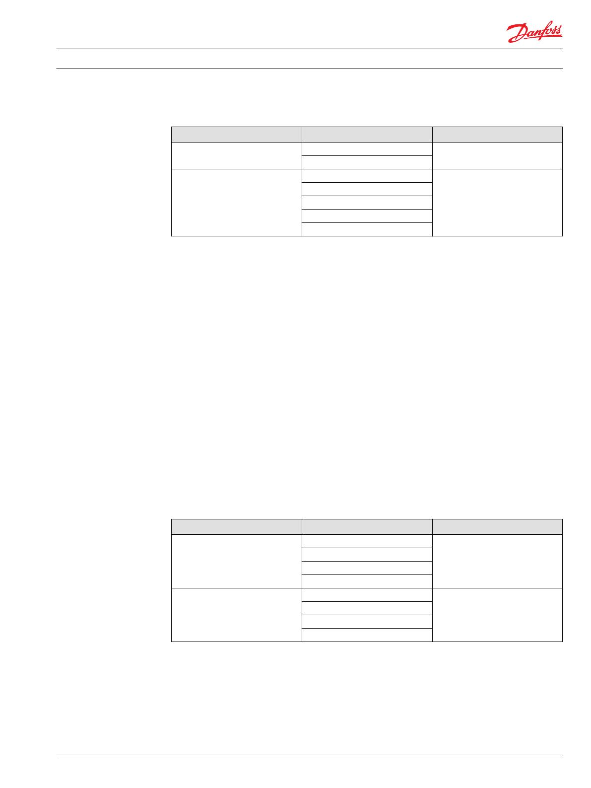
Loss of F1 Function Description (continued)
Failure Failed Part Description
Broken connection servo system to
swash plate
Swash plate Flow of the unit cannot be controlled
Servo piston assembly
High servo pressure differential due
to leakage
Servo cylinder assembly Pump does not move to neutral
Tycon glide ring
Housing crack at servo bores
Control gasket
Loss of solenoid
F2: Safe Stop (Pump to Neutral)
Hydraulic pressure up to the high pressure relief valve setting is sealed by the pump. The following table
describes the failures and failed parts that can lead to a failure of the function.
Detailed boundaries to prevent this failure mode:
Controls: EDC, NFPE (Input current is ramped down below application dependent threshold)
Control: FNR (Input current/voltage switched off)
Controls: MDC (Provide controlled and limited rotation of MDC input shaft towards neutral). Pump
displacement is directly proportional to the MDC input shaft rotation.
Controls: CCO part of NFPE, EDC or MDC (Input current/voltage is switched off, additionally apply
neutral signal to NFPE, EDC or MDC)
Control: FDC (Apply ramped current up or down to neutral current as specified in technical
information)
Controls: AC-1, AC-2:
o Provide requested displacement signal for neutral and / or deselect current high pressure port
o All AC parameters are set correctly as found with the prototype machine
Provide proper timing between park or holding brake engagement and displacement command
according to the application needs
Engine / prime mover has sufficient braking torque
Loss of F2 Function Description
Failure Failed Parts Description
Block Lift Cylinder roller bearing These failures decrease the block lift
speed. It means the block lift will
occur at lower speeds than maximum
allowed speed.
Snap ring
Valve plate
Retaining spring
System pressure not sealed Sticky check/high pressure valve The high pressure loop is bypassed so
no flow is backed up to create
braking pressure.
Cylinder block
Valve plate
End cap (high pressure core)
F3: Prevent Unexpected Movement
Without an input to the control, the pump must not create a system flow A/B. The following table
describes the failures and failed parts that can lead to a failure of the function.
Detailed boundaries to prevent this failure mode:
• Controls: EDC, NFPE, FNR (Input current for pump is zero)
Functional Safety
H1 Pumps 069-250 Product Reliability Data
Component Information and Calculations
70086000 • Rev CBMay 2015 9
• Control: FDC (Apply neutral current as specified in technical information)
• Controls: AC-1, AC-2 (No displacement requested)
• Controls: MDC (No force on MDC lever)
• Machine is stand still (zero vehicle speed)
• No differential pressure (machine is e.g. standing on incline); Park brake recommended
• Pump speed zero to max speed
Loss of F3 Function Description
Failure Failed Part Description
Breakage in feedback system (only
EDC)
Feedback link spring Loss of hydraulic neutral position,
free movement of control spool
Feedback link
Excenter
Feedback link
High servo pressure differential Loss of solenoid High servo pressure difference due to
leakage of one servo cylinder to a
lower pressure level
Control gasket
F4: CCO Function
When the CCO solenoid is de-energized, the pressure supply to the control is blocked and the pump
returns to a safe state where no output flow of the pump is being created.
Loss of F4 Function Description
Failure Failed part Description
No short circuit of servo pressures
after de-energizing of CCO solenoid
Sticky solenoid No short circuit between both servo
cylinders. No spring force that
swashes the pump back to neutral.
Sticky spool
F5: Safe Start
For the pump, this failure is equal to F1: Safe Controllability. The boundaries for the customer are
different. An input signal on the control solenoids C1 and C2 will lead to a proportional system flow A/B
of the hydraulic pump. The following table describes the failures and failed parts that can lead to a failure
of the function.
Detailed boundaries to prevent this failure mode:
Controls: EDC, NFPE (Input current is ramped from below threshold)
Control: FNR (Input current/voltage is switched on from neutral)
Control: FDC (Apply neutral current as specified in technical information)
Controls: AC-1, AC-2
o Select requested mode (1, 2, 3, or 4)
o Provide requested displacement signal
o All AC parameters are set correctly as found with the prototype machine
Controls: MDC (Provide controlled and limited rotation of MDC input shaft, torque within specified
torque limits)
Provide proper timing between park or holding brake release and displacement command according
to the application needs
Functional Safety
H1 Pumps 069-250 Product Reliability Data
Component Information and Calculations
10 70086000 • Rev CBMay 2015
Loss of F5 Function Description
Failure Failed part Description
Not returning to neutral Swash plate bearing Pump does not move to neutral
Sticky servo piston
Sticky PL-Valve
Sticky control spool/solenoid
Broken connection servo system to
swash plate
Swash plate Flow of the unit cannot be controlled
Swash piston assembly
High servo pressure differential due
to leakage
Servo cylinder assembly Pump does not move to neutral
Tycon glide ring
Housing crack at servo bores
Control gasket
Loss of solenoid
F6: Safe/Correct Direction of Rotation/Movement (Hydraulic Motor/Cylinder)
This failure can only be influenced by the customer. An example is the wrong wiring of control solenoids,
so the vehicle would drive in the opposite direction as expected. Or wrong outputs that are depending in
the software on the controller.
Detailed boundaries to prevent this failure mode:
Controls: EDC, NFPE (Input current is provided to the correct connector / solenoid)
Control: FDC (Apply ramped current up or down as specified in technical information)
Control: FNR (Input current / voltage is provided to the correct connector / solenoid)
Controls: MDC (Provide controlled and limited rotation of MDC input shaft in the correct direction,
torque within specified torque limits). Pump displacement is directly proportional to the MDC input
shaft rotation.
Controls: AC-1, AC-2
o Provide correct direction signal (FNR)
o AC output current is provided to the correct connector/solenoid
o All AC parameters are set correctly as found with the prototype machine
With negative load (e.g. downhill condition), the engine/prime mover needs to have sufficient
braking torque
Functional Safety
H1 Pumps 069-250 Product Reliability Data
Component Information and Calculations
70086000 • Rev CBMay 2015 11
List of References
These documents provide design theory and detailed calculations for building hydraulically powered
machines.
ISO 13849-1,2 Safety of machinery – Safety-related parts of control systems; ISO13839-1:2006,
ISO13849-2:2003
11062168 H1 Axial Piston Pumps, Single and Tandem Basic Information
H1 Weblink http://www.powersolutions.danfoss.com/Products/PistonPumpsandMotors/
ClosedCircuitMediumPowerPumpsMotors/index.htm
Functional Safety H1 Pumps 069-250 Product Reliability Data
References
12 70086000 • Rev CBMay 2015
Functional Safety H1 Pumps 069-250 Product Reliability Data
70086000 • Rev CBMay 2015 13
Functional Safety H1 Pumps 069-250 Product Reliability Data
14 70086000 • Rev CBMay 2015
Functional Safety H1 Pumps 069-250 Product Reliability Data
70086000 • Rev CBMay 2015 15
Danfoss Power Solutions is a global manufacturer and supplier of high-quality hydraulic and
electronic components. We specialize in providing state-of-the-art technology and solutions
that excel in the harsh operating conditions of the mobile off-highway market. Building on
our extensive applications expertise, we work closely with our customers to ensure
exceptional performance for a broad range of off-highway vehicles.
We help OEMs around the world speed up system development, reduce costs and bring
vehicles to market faster.
Danfoss – Your Strongest Partner in Mobile Hydraulics.
Go to www.powersolutions.danfoss.com for further product information.
Wherever off-highway vehicles are at work, so is Danfoss. We offer expert worldwide support
for our customers, ensuring the best possible solutions for outstanding performance. And
with an extensive network of Global Service Partners, we also provide comprehensive global
service for all of our components.
Please contact the Danfoss Power Solution representative nearest you.
Local address:
Danfoss
Power Solutions GmbH & Co. OHG
Krokamp 35
D-24539 Neumünster, Germany
Phone: +49 4321 871 0
Danfoss
Power Solutions ApS
Nordborgvej 81
DK-6430 Nordborg, Denmark
Phone: +45 7488 2222
Danfoss
Power Solutions (US) Company
2800 East 13th Street
Ames, IA 50010, USA
Phone: +1 515 239 6000
Danfoss
Power Solutions Trading
(Shanghai) Co., Ltd.
Building #22, No. 1000 Jin Hai Rd
Jin Qiao, Pudong New District
Shanghai, China 201206
Phone: +86 21 3418 5200
Danfoss can accept no responsibility for possible errors in catalogues, brochures and other printed material. Danfoss reserves the right to alter its products without notice. This also applies to
products already on order provided that such alterations can be made without changes being necessary in specifications already agreed.
All trademarks in this material are property of the respective companies. Danfoss and the Danfoss logotype are trademarks of Danfoss A/S. All rights reserved.
70086000 • Rev CB • May 2015 www.danfoss.com
©
Danfoss A/S, 2015
Products we offer:
Bent Axis Motors
Closed Circuit Axial Piston
Pumps and Motors
Displays
Electrohydraulic Power
Steering
Electrohydraulics
Hydraulic Power Steering
Integrated Systems
Joysticks and Control
Handles
Microcontrollers and
Software
Open Circuit Axial Piston
Pumps
Orbital Motors
PLUS+1
®
GUIDE
Proportional Valves
Sensors
Steering
Transit Mixer Drives
Comatrol
www.comatrol.com
Schwarzmüller-Inverter
www.schwarzmueller-
inverter.com
Turolla
www.turollaocg.com
Hydro-Gear
www.hydro-gear.com
Daikin-Sauer-Danfoss
www.daikin-sauer-danfoss.com
  • Page 1 1
  • Page 2 2
  • Page 3 3
  • Page 4 4
  • Page 5 5
  • Page 6 6
  • Page 7 7
  • Page 8 8
  • Page 9 9
  • Page 10 10
  • Page 11 11
  • Page 12 12
  • Page 13 13
  • Page 14 14
  • Page 15 15
  • Page 16 16

Danfoss H1 P User guide

Type
User guide

Danfoss H1 P is a high-performance axial piston variable displacement pump designed for use in closed circuit applications. With its compact design and high power density, it provides precise control over hydraulic flow rate and direction. The pump is compatible with Danfoss PLUS+1 microcontrollers for easy installation and operation. This pump excels in applications requiring proportional flow control, such as mobile machinery, industrial equipment, and marine vessels. Its versatility makes it suitable for a wide range of hydraulic systems, enabling efficient and reliable performance.

Ask a question and I''ll find the answer in the document

Finding information in a document is now easier with AI