
MANUALE DI ISTRUZIONI / INSTRUCTION MANUAL/ MANUAL DE INSTRUCCIONES / MANUAL DE INSTRUÇÕES / KÄYTTÖOHJEKIRJA
BANCO SEGA CON CARRELLO E
ADATTORE FRESATRICE /
TABLE SAW WITH CARRIAGE AND
MILLER ADPTER
SIERRA DE MESA CON RIELES Y
MOLINETE
SERRA DE MESA COM CARRIS
E MOLINETE
PÖYTÄSIRKKELI
(modello FOX F36-527C)
(FOX model F36-527C)
(Modelo FOX F36-527C
(FOX modelo F36-527C)
(malli FOX F36-527C)

INDICE / INDEX / ÍNDICE/ SUMARIO / SISÄLTÖ
ITALIANO (IT) Manuale originale,Original manual,Manuel original,Käännös ohjekirjasta .................... 1 ÷ 34
ENGLISH (EN) Manual translated from the original, manuale tradotto dall’originale............................ 35 ÷ 66
ESPANOL (ES) Manual translated from the original, manuale tradotto dall’originale............................ 67 ÷ 98
PORTUGUÊS (PT) Manual Traduzido do Original, manuale tradotto dall’originale .................................. 99 ÷ 130
SUOMI (FI) Alkuperäisestä käännetty käyttöohje,, manuale tradotto dall’originale .................... 131 ÷ 162
DICHIARAZIONE DI CONFORMITA’/ DECLARATION OF CONFORMITY / DECLARACIÓN DE
CONFORMIDAD / DECLARAÇÃO DE CONFORMIDADE / VAATIMUSTENMUKAISUUSVAKUUTUS
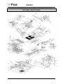
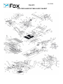
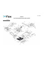
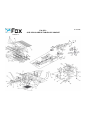
ESPLOSO / EXPLODED VIEW / VISTA DETALLADA / VISTA DETALHADA / RÄJÄYTYSKUVA
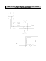
SCHEMA ELETTRICO / WIRING DIAGRAM / ESQUEMA ELÉCTRICO / ESQUEMA ELÉCTRICO /
SÄHKÖKYTKENTÄKAAVIO
Page is loading ...
Page is loading ...
Page is loading ...
Page is loading ...
Page is loading ...
Page is loading ...
Page is loading ...
Page is loading ...
Page is loading ...
Page is loading ...
Page is loading ...
Page is loading ...
Page is loading ...
Page is loading ...

17
IT
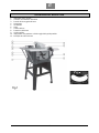
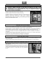
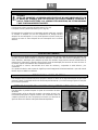
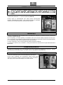
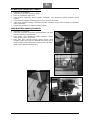
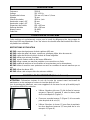
DESCRIZIONE DEL BANCO SEGA
1. Interruttore avvio / arresto
2. Volantino di inclinazione della lama
3. Pomello di bloccaggio della lama
4. Spingipezzo
5. Goniometro
6. Lama
7. Coltello divisore
8. Protezione della lama
9. Guida parallela
10. Impugnatura di regolazione e di bloccaggio della guida parallela
11. Manopola di salita e discesa
Page is loading ...

19
IT
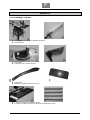
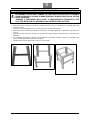
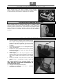
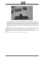
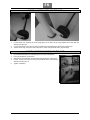
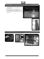
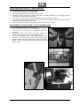
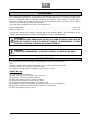
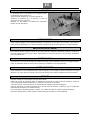
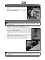
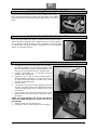
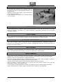
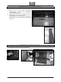
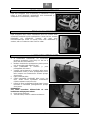
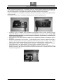
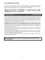
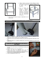
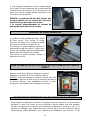
MONTAGGIO DELLE RUOTE SULLA BASE
1. Fissate i supporti di bloccaggio delle ruote (O) sui montanti del basamento (H) utilizzando le viti M6x16
mm con le rondelle e i dadi.
2. Attaccate le ruote all’asse (M) poi montate l’asse tra i supporti di bloccaggio delle ruote (O).
3. Aggiungete un anello elastico (U) ad ogni estremità dell’asse, in modo da mantenere le ruote nella loro
sede.
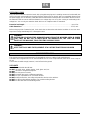
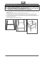
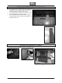
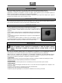
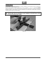
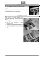
MONTAGGIO DEL PIANO DI LAVORO DELLA SEGA SULLA BASE
1. Assicuratevi che la lama sia completamente rientrata nel piano.
2. Posizionate il piano della sega sul basamento.
3. Allineate i fori del basamento con i fori corrispondenti situati sulla base
della sega circolare.
4. Fissate la sega circolare al basamento utilizzando 4 viti M6x16 mm con
le rondelle e i dadi (T).
5. Stringete completamente.

20
IT
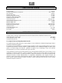
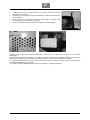
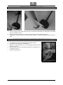
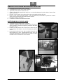
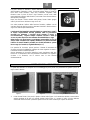
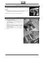
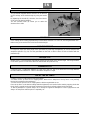
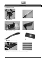
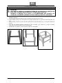
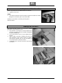
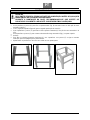
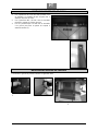
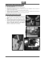
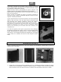
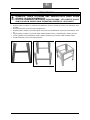
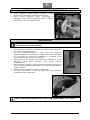
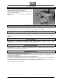
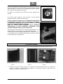
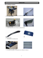
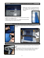
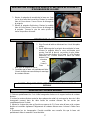
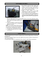
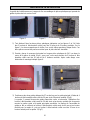
MONTAGGIO DELL’ESTENSIONE POSTERIORE DEL PIANO DI LAVORO
1. Utilizzate le 3 viti M5 x 16 mm, ognuna con una
rondella e una rondella freno (Z) per fissare
l’estensione (F) al piano di lavoro del banco sega.
2. Utilizzate le due viti M5 x 20 mm con le rondelle per
fissare i pezzi di appoggio (L) sul telaio del banco
sega.
3. Utilizzate le due viti M5 x 20 mm con le rondelle e i
dadi per fissare i pezzi di appoggio sull’estensione
posteriore (F).
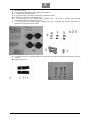
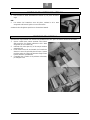
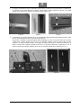
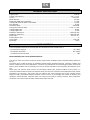
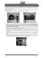
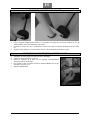
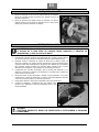
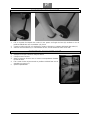
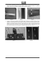
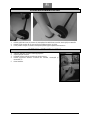
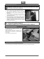
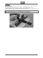
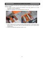
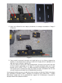
MONTAGGIO DEI SUPPORTI DELLO SPINGIPEZZO
Per montare i supporti dello spingipezzo, osservate le seguenti foto.
1 2
3
Page is loading ...
Page is loading ...
Page is loading ...
Page is loading ...
Page is loading ...
Page is loading ...
Page is loading ...
Page is loading ...
Page is loading ...
Page is loading ...
Page is loading ...
Page is loading ...

33
IT
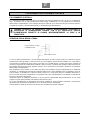
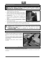
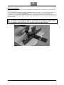
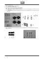
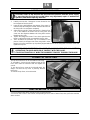
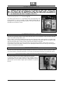
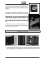
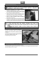
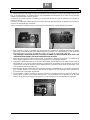
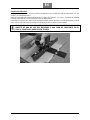
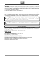
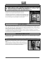
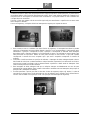
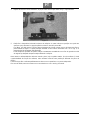
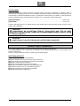
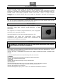
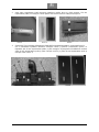
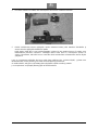
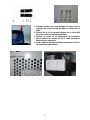
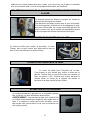
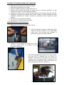
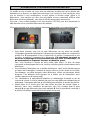
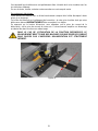
Allacciamenti elettrici:
La vostra macchina è dotata di un kit di collegamento composto da un alimentatore a due prese e un
interruttore-invertitore.
Questo alimentatore deve essere fissato al basamento della macchina e la vostra segatrice circolare e la
vostra fresatrice devono
NECESSARIAMENTE
essere connesse correttamente a questo alimentatore.
Premendo sul pulsante a leva dell’interruttore-invertitore, alimenterete o la presa di corrente della fresatrice o la
presa di corrente della vostra segatrice. Questo collegamento impedisce l’avvio accidentale delle due funzioni
allo stesso tempo.
NEL CASO DELL’UTILIZZO DELLA FUNZIONE FRESATRICE, È RIGOROSAMENTE
VIETATO IL COLLEGAMENTO DIRETTO DI UNA DELLE MACCHINE SU UNA PRESA DI
CORRENTE SENZA PASSARE PER L’INVERTITORE DI ALIMENTAZIONE.
Figura 10
Page is loading ...

35
EN
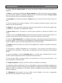
INDEX
SAFETY INSTRUCTIONS ................................................................................................................... 37
PERSONNEL AUTHORIZED TO USE THE MACHINE ...................................................................... 37
GENERAL SAFETY INSTRUCTIONS ................................................................................................. 38
SPECIFIC SAFETY INSTRUCTIONS FOR CIRCULAR SAWS .......................................................... 39
SAFETY INSTRUCTIONS FOR THE LASER POINTING DEVICE ..................................................... 40
ENVIRONEMENT PROTECTION ........................................................................................................ 40
INFORMATION FOR USERS .......................................................................................................... 40
SYMBOLS ............................................................................................................................................ 41
ELECTRICAL CONNECTIONS ........................................................................................................... 42
ELECTRICAL CONNECTIONS ....................................................................................................... 42
EARTHING INSTRUCTIONS .......................................................................................................... 42
EXTENSION LEADS ....................................................................................................................... 43
RECOMMENDED USE ........................................................................................................................ 43
USE LIMITS ..................................................................................................................................... 43
TECHNICAL SPECIFICATIONS .......................................................................................................... 44
NOISE CONDITIONS ........................................................................................................................... 44
REMOVAL OF PACKAGE ................................................................................................................... 45
MACHINE DESCRIPTION ................................................................................................................... 49
ASSEMBLY OF THE BASE ................................................................................................................ 50
ASSEMBLY OF THE WHEELS TO THE BASE .................................................................................. 51
ASSEMBLY OF THE WORKBENCH TO THE BASE ......................................................................... 51
ASSEMBLY OF WORKBENCH’S BACK EXTENSION ...................................................................... 52
ASSEMBLY OF THE PUSHER HANGER ........................................................................................... 52
ASSEMBLY OF SIDE EXTENSION .................................................................................................... 53
ASSEMBLY OF THE CARRIAGE ....................................................................................................... 53
ASSEMBLY OF HEIGHT AND ANGLE ADJUST HANDWHEELS ..................................................... 54
ASSEMBLY OF THE BLADE .............................................................................................................. 54
ASSEMBLY OF THE RIVING KNIFE ..................................................................................................
55
ASSEMBLY OF THE RIP FENCE ....................................................................................................... 55
FIXING THE MACHINE TO THE GROUND ......................................................................................... 55
STARTING THE TABLE SAW ............................................................................................................. 56
PROTECTIVE THERMAL CUT-OUT ................................................................................................... 56
SAW BLADE BRAKING ...................................................................................................................... 56
LOCK KNOB OF BLADE’S HEIGHT ADJUST HANDWHEEL ........................................................... 56
BLADE’S HEIGHT ADJUST HANDWHEEL........................................................................................ 57
BLADE’S ANGLE ADJUST HANDWHEEL......................................................................................... 57
LASER POINTING DEVICE ADJUSTMENT ....................................................................................... 57
GONIOMETER ..................................................................................................................................... 58
CROSSCUT ......................................................................................................................................... 58
ANGLE CROSSCUT ............................................................................................................................ 58
OBLIQUE CUT ..................................................................................................................................... 58
COMPOSED CUT ................................................................................................................................ 58
USE OF THE RIP FENCE .................................................................................................................... 58
Page is loading ...

37
EN
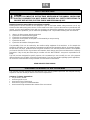
SAFETY INSTRUCTIONS
CAUTION:
BESIDES FOLLOWING THE INSTRUCTIONS MENTIONED IN THIS MANUAL, WHEN USING
ELECTRIC EQUIPMENT YOU MUST ALWAYS OBSERVE ALL SAFETY PRECAUTIONS TO
PREVENT RISK OF FIRE, ELECTRIC SHOCK AND PERSONAL INJURY.
Read this instruction manual before use and keep it carefully.
Working with an electric machine can be dangerous if you do not follow suitable safety measures. As for any
electric machine with moving parts, the use of a tool entails some risks. If you use the machine as prescribed in this
manual, you pay careful attention to the work you are doing, you observe the regulations and you use the suitable
personal devices of protection, you can reduce the probability of risk. The possible remaining risks are related to:
1. direct or in direct contacts with electrical shock
2. injuries due to contact with moving parts
3. injuries due to contact with angular parts
4. injuries due to the ejection of tool parts or of the material you are processing
5. injuries due to noise
6. injuries due to inhalation of dangerous dust
The probability of risk can be reduced by the machine safety equipment of the machines, as for example the
protections, the blade case, the clamping, the stoppage and the personal protection devices as protective goggles,
the dust mask, ear plugs, protective shoes and gloves. However, even the best protection devices cannot protect
you from the risks due to lack of good sense and attention. Have always good sense and observe the necessary
precautions. Carry out only the works that you consider safe. DO NOT FORGET: everyone is responsible for his
safety.
This tool has been designed for specific purposes. We recommend you not to modify it or use it for purposes
different from the ones for which it has been manufactured. If you have any doubts regarding specific applications,
do not use the machine before having contacted us and received our instructions.
READ AND KEEP THIS MANUAL
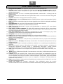
PERSONNEL AUTHORIZED TO USE THE MACHINE
This machine has been designed and manufactured to be used by qualified personnel with adequate training,
experience and skills. Below you will find a list of basic requirements:
Operators / Trainees / Apprentices:
may be male or female
must be aged 14 or over
must have full use of both hands
must have no physical or mental disabilities
must know and fully understand the contents of the user manual.

38
EN
GENERAL SAFETY INSTRUCTIONS
1. Keep the work surface clean. If the work area or surface is busy the probability of injuries is higher.
2. Do not use the machine in dangerous environment conditions. In order to prevent electric shock, do not
expose the machine to rain and do not use it in a damp area. Keep the work area illuminated. Do not use
the machine near gas or inflammable substances.
3. Connect the dust collection device. If the machine is provided with a dust collection device, make sure that
this system is connected and correctly used.
4. Keep unknown persons and children away from the machine. All unknown persons and children must keep a
safe distance from the work area.
5. Protect yourself from electric shock. Avoid any contact with earthing surfaces.
6. Handle the power supply cable with care. Do not pull the electric cable to disconnect it from the plug. Keep
the electric cable away from heat, oil and sharp edges.
7. Use extension cables designed for outdoor use. When using the machine outdoors, use only extension cables
suitable for outdoor use, having specific indications.
8. Be vigilant. Check carefully what you are doing, have good sense. Do not use the machine if you are tired.
9. Do not use the machine if you are have taken medicines, alcohol, drugs.
10. Avoid accidental starts. Be sure that the switch is on the OFF position before inserting the plug into the
socket.
11. Wear appropriate clothing. Do not wear loose-sleeved garments or pieces of jewellery which may get caught
in the moving parts. For outdoor use we recommend non-slip shoes. Use headgear to cover hair if necessary.
12. Use always personal protection devices: wear protective goggles and masks in case dust or sawdust is
produced. Wear ear muffs or plugs in noisy areas. Wear gloves when handling parts with sharp edges.
13. Do not be off balance over the machine. Always keep stand firmly.
14. Ask for advices to expert and qualified people if you are not familiar with using such a machine.
15. Remove the tools you do not use from the workbench. If you do not use the tools, you must arrange them in a
dry area which is locked and away from the reach of children.
16. Do not force the machine. You can obtain better and safer results if you use the machine at the cutting
pressure for which it has been designed.
17. Use the suitable tool. Do not use a small tool for an intensive job. Fox example, do not use a circular saw to
cut branches or stumps.
18. Block the piece. If possible, use C-clamps or a holder to fix the piece. It is safer than using only your hands.
19. Keep the tools in perfect conditions. Keep the tools sharp and clean to obtain better and safer results. Follow
the instructions to grease and change the accessories. Check regularly the electric cable and change it if it is
damaged. Keep the handles and the handgrips dry, clean, unoiled and ungreased.
20. Disconnect the tool from electricity if you do not use it, before maintenance and change of the accessories or
tools such as blades, drills, mills, etc.
21. Remove locking and adjustment wrenches from the workbench. Get used to check if the locking and
adjustment wrenches have been removed before starting it.
22. Check the parts of the tool to verify that there are not any damages. Before using the machine, check if the
safety devices or any other parts are damaged in order to be sure that it works properly and that it can
accomplish the tasks for which it has been designed. Check that the moving parts are aligned, do not stop and
are not broken. Check the assembly and any other condition that can influence the functioning of the machine.
Any part or protection damaged must be repaired or changed from an authorised after sales centre. Do not
use the machine if the switch does not work properly.
23. Use the machine, the tools and accessories in the way and for the purposes mentioned i this manual. Different
uses and parts can cause possible risks for the operator.
24. Get the machine repaired by a qualified person. This electric tool is in compliance with local safety
regulations. The machine must be repaired only by qualified people who use original spareparts, otherwise
risks may arise for the operator.

39
EN
SPECIFIC SAFETY INSTRUCTIONS FOR CIRCULAR SAWS
1. DO NOT start the saw until it is assembled and installed according to the instructions of this manual.
2. ALWAYS USE the protective cap, the riving knife and the clamping device in order to cut the piece
completely. This means cutting the piece in all its depth.
3. ALWAYS PRESS the workpiece firmly against the oblique guide or on the rip fence.
4. USE always a clamping device in order to push the piece of wood through the blade and in particular to cut
small pieces. To get further information on the clamping device, check the sections regarding longitudinal
cutting in this manual.
5. NEVER work freehand. Always use the oblique guide or the rip fence to position and direct the piece you are
cutting.
6. ALWAYS KEEP A SAFE DISTANCE from the blade track. KEEP the hands away from the blade’s track.
7. DO NEVER keep your hands behind or over the blade and ensure that you and your hands are in a
comfortable position.
8. REMOVE the rip fence during cross cutting.
9. DO NOT USE the rip fence for cross cutting.
10. PUSH ALWAYS the piece you have to cut through the saw blade or the tool.
11. DO NOT TRY to remove the saw blade before switching off the tool. Also if you want to stop cutting, put the
switch on the OFF position and wait for the blade to stop rotating. You can perform tasks of any kind only if the
blade is still and the machine is disconnected from the power supply.
12. DO NOT remove wood piles caught between the blade and the inlet if the blade is rotating. You can intervene
after switching off the machine and having waited for the blade to stop rotating.
13. LEAN on a support the ends of big workpieces which come out sideways or behind the workbench.
14. AVOID workpieces hittig back in your direction by taking the following measures:
Always use a sharp and suitable saw blade;
Check the parallelism between the guide and the blade;
Always use the riving knife, the clamping device and the protective cap;
Never release the workpiece before it has been completely pushed through the saw;
Do not saw bent or deformed workpieces which do not have a straight side that allows a regular
advancement along the guide.
15. NEVER USE thinners to clean the plastic pieces of the machine. Thinners can melt or damage the material.
Only use a damp cloth for cleaning plastic workpieces.
16. INSTALL the saw PERMANENTLY on a plane surface before using it.
17. DO NEVER CUT any metals or materials that can produce dangerous dust.
18. ALWAYS USE the table saw in a well ventilated area. Often remove the sawdust. Remove carefully the
sawdust that is inside the saw to avoid the risk of fire.
19. DO NOT use saw blades which are damaged or deformed or high speed blades in high alloy ( as for example
HSS ).
20. USE only saw blades recommended by the manufacturer, in compliance with EN 847-1 standard.
21. USE only correct saw blades, which are suitable to the material to be cut and on which the marked speed is
higher than the one of the machine. When changing the blade, check if external diameter and bore diameter
are correct, that cutting width and the blade body are not thinner than the riving knife width. Transport the saw
blade inside its case.
22. CHANGE the plastic table inlay which is located on the table around the blade when worn or damaged.
23. USE this table saw only to cut wood and similar materials.
24. CHECK often if the supply cable is damaged, and in this case get it repaired by an authorized after sales
center. Check often the extension cord and change it if it is damaged.
25. CONNECT the machine to a dust-collecting device and USE ear protective devices and the dust mask.

40
EN
SAFETY INSTRUCTIONS FOR THE LASER POINTING DEVICE
Never look towards the laser pointing device.
Do not direct the pointing device towards people or animals.
Do not use the pointing device on very reflective surfaces. The reflected light is as dangerous as direct light.
Get the pointing device repaired only by qualified technicians.
Do not touch the pointing device’s lens with hard objects.
Clean the pointing device’s lens with a soft and dry brush.
If necessary, you must change the pointing device with one of the same kind.
ENVIRONEMENT PROTECTION
INFORMATION FOR USERS
In accordance with art. 13 of Legislative Decree 25th July 2005, no. 151 “Implementation of Directives
2002/95/EEC, 2002/96/EEC and 2003/108/EEC, relative to reducing the use of hazardous substances in electric
and electronic appliances and the disposal of waste”, please take note of the following:
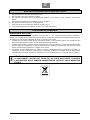
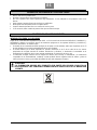
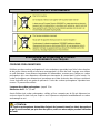
The crossed out wheelie bin symbol found on the appliance or the packaging indicates that the product must
be disposed separately from ordinary household waste when it reaches the end of its working life.
The user must consign the unwanted appliance to an authorized waste disposal centre for electric and
electronic goods, or alternatively, hand it over to the relative dealer at the moment of purchasing a new
appliance of the same type on a basis of a one to one ratio.
Differentiated disposal to enable possible recycling or environmentally compatible elimination of the appliance,
helps to limit undesirable effects on health and environment and promotes the reuse and/or recycling of the
materials that compose the appliance.
WARNING!
IN ACCORDANCE WITH THE RELATIVE LEGISLATION IN FORCE IN THE COUNTRY OF
USE, SANCTIONS WILL BE IMPOSED ON THE USER IF THE APPLIANCE IS DISPOSED OF
ILLEGALLY.

41
EN
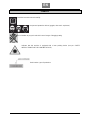
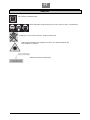
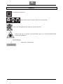
SYMBOLS
Read the instruction manual carefully
Use personal protection devices (goggles, dust mask earphones)
It is forbidden to put your hands in this area. Danger of dragging/cutting.
Indicates that this machine is equipped with a laser pointing device (see par. SAFETY
INSTRUCTIONS FOR THE POINTING DEVICE).
Serial number / year of production

42
EN
ELECTRICAL CONNECTIONS
ELECTRICAL CONNECTIONS
Use 230 V 50 Hz alternate voltage equipped with a earthing conductor to supply your machine. Ensure that the
power supply corresponds to this voltage, that it is protected by a differential and magnetothermal switch, and that
the earthing system is efficient. If your machine does not work when connected to a socket, check carefully the
power supply features.
Use an extension cable in order to connect the machine to the power supply.
WHEN YOU ARE USING THE MILLER, YOU MUST ABSOLUTELY USE THE POWER
SUPPLY DEVICE PROVIDED WITH THE MILLER KIT. THIS POWER SUPPLY ALLOWS YOU
TO START THE SAW OR THE MILLER INDEPENDENTLY.
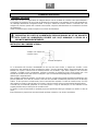
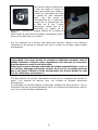
EARTHING INSTRUCTIONS
If the tool does not work properly or in case of short-circuit, the earthing system provides the current with a less
resistance path and reduces the risk of electric shock. This tool has a plug to which a supply or extension cable
must be connected, which in turn must be connected to a socket correctly installed and earthed, in conformity with
local standards and regulations. Be sure that your earthing system is in good conditions and that your plug is
protected by a differential and magnetothermal switch.
Do not modify the plug of the machine. If it does not enter the socket, get a suitable plug installed by a qualified
person. If the earthing conductor is not correctly connected the risk of electric shock can occur. The conductor
which has the green insulating jacket (with or without a yellow line) is the earthing conductor. If you must repair or
change the supply cable, do not connect the earthing conductor to a low tension terminal.
Consult a qualified electrician or a person in charge of the maintenance if you have not understood or you have
some doubts on the earthing instructions.
If the supply cable is damaged it must be changed by qualified people. Do not switch on the machine if the supply
cable is damaged.
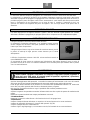
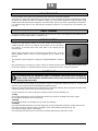
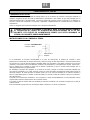
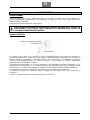
This tool is provided with a plug which must connected to a suitable socket.
Socket with earthing system
Earth conducto
r
Machine’s plug

43
EN
EXTENSION LEADS
Only use three conductors extension leads, with a plug with two plugs and a earthing contact and sockets with two
holes and a earth corresponding to the plug of the tool. When using an electric tool at a remarkable distance from
the power supply, use an extension cable with sufficient dimensions to transport the current which the tool needs. If
the extension lead has not the sufficient dimensions a voltage drop can occur, thus causing an overheating and a
voltage loss. You can only use extension leads which are in compliance with CE standards.
Extension lead length:
.......................................................................................................................... up to 15 m
Cable dimensions
: ............................................................................................................................... 3 x 2,5 mm²
Before using any kind of extension lead, check that it has not bare wires and that the insulation is not cut or worn.
Repair and change immediately it if it is damaged or worn.
WARNING:
EXTENSION LEADS MUST BE ARRANGED AWAY FROM THE WORKING AREA IN ORDER
THAT THEY DO NOT GET IN TOUCH WITH THE WORKPIECES, THE TOOL OR OTHER
PARTS OF THE MACHINE, THUS CREATING POSSIBLE RISKS.
WARNING:
KEEP THE TOOLS AND THE EQUIPMENT AT A SAFE DISTANCE FROM CHILDREN
RECOMMENDED USE
This machine has been manufactured only for longitudinal and cross cutting of soft and hard wood.
The blade can be angled from 0 to 45° and if the blade is at 0° it can cut up to 80 mm, while at 45° it can cut up to
55 mm.
The machine is stable enough, however, it can be fixed to the ground
USE LIMITS
DO NOT
cut wood wider than 80 mm.
DO NOT
cut metal, stone, rubber, plastics, chalk, glass wool, etc.
DO NOT
cut stubs or irregular wood pieces.
DO NOT
use it to groove or mould.
DO NOT
assemble other tools or different saw blades.
DO NOT
use it as a portable tool or a not fixed machine.
DO NOT
modify the machine, the safety and protection devices or the switches.
DO NOT
use the machine without protective cap or without safety devices.
DO NOT
use this table saw to make blind grooves.

44
EN
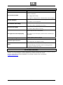
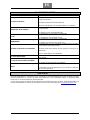
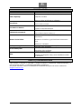
TECHNICAL SPECIFICATIONS
Engine power: .................................................................................................................................................. 1500 W
Voltage and frequency: .......................................................................................................................... 230 V - 50 Hz
Service: ....................................................................................................................................................... continuous
Blade diameter: ............................................................................................................................................... 254 mm
Blade body width when assembled: ................................................................................................................ 1,8 mm
Cutting width when the blade is assembled: ................................................................................................... 2,8 mm
Bore diameter: .................................................................................................................................................. 30 mm
Rotational speed: ........................................................................................................................................ 4500 RPM
Riving knife and holes width: .............................................................................................................. 2 mm – 6,2 mm
Cutting height at 90°: ........................................................................................................................................ 80 mm
Cutting height at 45°: ........................................................................................................................................ 55 mm
Workbench dimensions: ....................................................................................................................... 638 x 430 mm
Workbench extensions: ........................................................................................................................ 638 x 260 mm
Blade angle: ........................................................................................................................................... from 0 to 45 °
Pointing device class: ............................................................................................................................................... 1°
Laser power: ................................................................................................................................................ < 111 mW
Net weight: .......................................................................................................................................................... 38 Kg
NOISE CONDITIONS
The noise emitted, measured in conformity with the standards EN 3744 and EN 11201 is:
- Sound pressure level LpA ......................................................................................................................... 99,3 dB(A)
- Sound power level
L
WA ......................................................................................................................... 112,3 dB(A)
- Uncertainty of measurement K .......................................................................................................................... 3 dB.
We recommend you to use ear protection devices.
The sources of the noise of the saw are the electric engine and its ventilation system, the blade and the material to
be cut.
We advise you to control the engine, its ventilation system and the aspiration passages. Check the condition and
tension of the belt. As far as the saw blade is concerned, it is preferable to use silenced type of blades and to keep
them in good conditions. We recommend you to use the correct saw blade and to keep firmly the workpiece to be
cut.
Noise levels are emission levels and do not necessarily indicate safe working conditions. Even if there is a
connection between emission levels and exposure levels, the first ones cannot be used to determine safely if other
precautions are necessary. The factors that can influence the actual exposure level of the operator include
exposure length, environment features and other sources of noise, as for example the number of machines and
operations present. Besides, exposure levels can change from country to country. However, these instructions
enable the user of the machine to better evaluate the dangers and risks.

45
EN
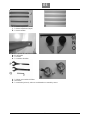
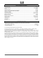
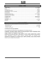
REMOVAL OF PACKAGE
In the package you can find:
A. Table saw and miller adapter
B. Rip fence
C. Goniometer
D. Protective cap and riving knife
E. Pusher
F. Workbench’s back extension
G. 1 x workbench side extension
H. 4 x feet with slides and rubber (not present in the figure above)

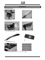
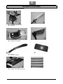
46
EN
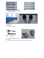
I. 2 x upper bars (small)
J. 2 x upper bars (long)
K. 4 x medium bars
L. 2 x bearing of back extensions
M. Wheel axle
N. 2 x wheels
O. 2 x wheel supports
P. 2 x wrenches for changing the blade
Q. Allen wrench
R. 2 x handwheels (lever), each supplied with a washer and a nut

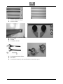
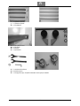
47
EN
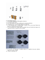
S. 32 x bolts and nuts
T. 4 x hexagonal screws to lock extensions
U. 2 x elastic rings (wheels’ axle)
V. 4 x lock screws with knurled bolt for side extensions
W. 2 tongues with 4 screws for supporting the pusher
X. 2 x main screws with two flat washers, stop washers and nut to fix the supports on the back extension of
the workbench
Y. 2 x main screws with two flat washers and stop washers to fix the angle bars of the back extension of the
table saw
Z. 3 x screws M5 x 16 mm with 3 flat washers and 2 stop washers to connect workbench’s back extension
AC. Rubber feet x 4

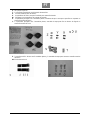
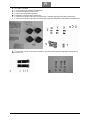
48
EN
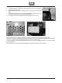
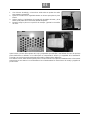
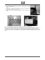
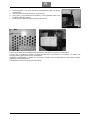
1. Turn the workbench and its base upside-down on a piece of cardboard in
order to protect its surface.
2. Remove the 4 safety screws located on the base in order to remove the lower
plate.
3. Remove the cardboard and the protection polystyrene around the motor and
the blade (this protection is necessary during transport).
4. Then put the plate in its starting position and tighten the 4 lock screws.
Remove the saw and all other parts from the packaging and check that nothing is missing or damaged.
In case there are faulty or damaged parts, do not use them in order not to compromise the efficiency and the safety
of the tool. Consult an authorized after sales service to replace any faulty parts.
To use the table saw, you must assemble some parts. You can find a detailed explanation on how to assemble
these parts later on.
We recommend you to read carefully the assembly instructions and to follow them to the letter.

49
EN
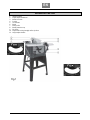
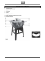
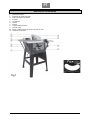
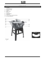
MACHINE DESCRIPTION
1. ON/OFF switch
2. Angle adjust handwheel
3. Blade lock knob
4. Pusher
5. Goniometer
6. Blade
7. Riving knife
8. Blade protective cap
9. Rip fence
10. Adjust and locking handgrip of the rip fence
11. Height adjust handle
Page is loading ...
Page is loading ...
Page is loading ...
Page is loading ...
Page is loading ...
Page is loading ...
Page is loading ...
Page is loading ...
Page is loading ...
Page is loading ...
Page is loading ...
Page is loading ...
Page is loading ...
Page is loading ...
Page is loading ...
Page is loading ...
Page is loading ...
Page is loading ...
Page is loading ...
Page is loading ...
Page is loading ...
Page is loading ...
Page is loading ...
Page is loading ...
Page is loading ...
Page is loading ...
Page is loading ...
Page is loading ...
Page is loading ...
Page is loading ...
Page is loading ...
Page is loading ...
Page is loading ...
Page is loading ...
Page is loading ...
Page is loading ...
Page is loading ...
Page is loading ...
Page is loading ...
Page is loading ...
Page is loading ...
Page is loading ...
Page is loading ...
Page is loading ...
Page is loading ...
Page is loading ...
Page is loading ...
Page is loading ...
Page is loading ...
Page is loading ...
Page is loading ...
Page is loading ...
Page is loading ...
Page is loading ...
Page is loading ...
Page is loading ...
Page is loading ...
Page is loading ...
Page is loading ...
Page is loading ...
Page is loading ...
Page is loading ...
Page is loading ...
Page is loading ...
Page is loading ...
Page is loading ...
Page is loading ...
Page is loading ...
Page is loading ...
Page is loading ...
Page is loading ...
Page is loading ...
Page is loading ...
Page is loading ...
Page is loading ...
Page is loading ...
Page is loading ...
Page is loading ...
Page is loading ...
Page is loading ...
Page is loading ...
Page is loading ...
Page is loading ...
Page is loading ...
Page is loading ...
Page is loading ...
Page is loading ...
Page is loading ...
Page is loading ...
Page is loading ...
Page is loading ...
Page is loading ...
Page is loading ...
Page is loading ...
Page is loading ...
Page is loading ...
Page is loading ...
Page is loading ...
Page is loading ...
Page is loading ...
Page is loading ...
Page is loading ...
Page is loading ...
Page is loading ...
Page is loading ...
Page is loading ...
Page is loading ...
Page is loading ...
Page is loading ...
Page is loading ...
Page is loading ...
Page is loading ...
Page is loading ...
Page is loading ...
Page is loading ...
Page is loading ...
Page is loading ...
Page is loading ...
Page is loading ...
Page is loading ...
Page is loading ...
Page is loading ...
Page is loading ...
Page is loading ...
Page is loading ...
Page is loading ...
Page is loading ...
Page is loading ...
Page is loading ...
Page is loading ...
Page is loading ...
Page is loading ...
Page is loading ...
Page is loading ...
Page is loading ...
Page is loading ...
Page is loading ...
Page is loading ...
Page is loading ...
Page is loading ...
Page is loading ...
Page is loading ...
Page is loading ...
Page is loading ...
Page is loading ...
Page is loading ...
Page is loading ...
Page is loading ...
Page is loading ...
Page is loading ...
Page is loading ...
Page is loading ...
Page is loading ...
Page is loading ...
Page is loading ...
-
 1
1
-
 2
2
-
 3
3
-
 4
4
-
 5
5
-
 6
6
-
 7
7
-
 8
8
-
 9
9
-
 10
10
-
 11
11
-
 12
12
-
 13
13
-
 14
14
-
 15
15
-
 16
16
-
 17
17
-
 18
18
-
 19
19
-
 20
20
-
 21
21
-
 22
22
-
 23
23
-
 24
24
-
 25
25
-
 26
26
-
 27
27
-
 28
28
-
 29
29
-
 30
30
-
 31
31
-
 32
32
-
 33
33
-
 34
34
-
 35
35
-
 36
36
-
 37
37
-
 38
38
-
 39
39
-
 40
40
-
 41
41
-
 42
42
-
 43
43
-
 44
44
-
 45
45
-
 46
46
-
 47
47
-
 48
48
-
 49
49
-
 50
50
-
 51
51
-
 52
52
-
 53
53
-
 54
54
-
 55
55
-
 56
56
-
 57
57
-
 58
58
-
 59
59
-
 60
60
-
 61
61
-
 62
62
-
 63
63
-
 64
64
-
 65
65
-
 66
66
-
 67
67
-
 68
68
-
 69
69
-
 70
70
-
 71
71
-
 72
72
-
 73
73
-
 74
74
-
 75
75
-
 76
76
-
 77
77
-
 78
78
-
 79
79
-
 80
80
-
 81
81
-
 82
82
-
 83
83
-
 84
84
-
 85
85
-
 86
86
-
 87
87
-
 88
88
-
 89
89
-
 90
90
-
 91
91
-
 92
92
-
 93
93
-
 94
94
-
 95
95
-
 96
96
-
 97
97
-
 98
98
-
 99
99
-
 100
100
-
 101
101
-
 102
102
-
 103
103
-
 104
104
-
 105
105
-
 106
106
-
 107
107
-
 108
108
-
 109
109
-
 110
110
-
 111
111
-
 112
112
-
 113
113
-
 114
114
-
 115
115
-
 116
116
-
 117
117
-
 118
118
-
 119
119
-
 120
120
-
 121
121
-
 122
122
-
 123
123
-
 124
124
-
 125
125
-
 126
126
-
 127
127
-
 128
128
-
 129
129
-
 130
130
-
 131
131
-
 132
132
-
 133
133
-
 134
134
-
 135
135
-
 136
136
-
 137
137
-
 138
138
-
 139
139
-
 140
140
-
 141
141
-
 142
142
-
 143
143
-
 144
144
-
 145
145
-
 146
146
-
 147
147
-
 148
148
-
 149
149
-
 150
150
-
 151
151
-
 152
152
-
 153
153
-
 154
154
-
 155
155
-
 156
156
-
 157
157
-
 158
158
-
 159
159
-
 160
160
-
 161
161
-
 162
162
-
 163
163
-
 164
164
-
 165
165
-
 166
166
-
 167
167
-
 168
168
-
 169
169
-
 170
170
-
 171
171
-
 172
172
-
 173
173
-
 174
174
-
 175
175
-
 176
176
-
 177
177
-
 178
178
-
 179
179
-
 180
180
-
 181
181
-
 182
182
-
 183
183
-
 184
184
-
 185
185
-
 186
186
-
 187
187
-
 188
188
-
 189
189
-
 190
190
-
 191
191
-
 192
192
-
 193
193
-
 194
194
-
 195
195
-
 196
196
-
 197
197
-
 198
198
-
 199
199
-
 200
200
-
 201
201
-
 202
202
-
 203
203
-
 204
204


Ask a question and I''ll find the answer in the document
Finding information in a document is now easier with AI
in other languages
- italiano: Fox F36-527C Manuale utente
- français: Fox F36-527C Manuel utilisateur
- español: Fox F36-527C Manual de usuario
- português: Fox F36-527C Manual do usuário
- suomi: Fox F36-527C Ohjekirja
Related papers
Other documents
-
 Valex 1410219 Owner's manual
-
 Valex 1390219 Owner's manual
-
 Valex 1390221 Owner's manual
-
 Valex 1390306 Owner's manual
-
 Valex 1432523 Owner's manual
-
 Valex 1411141 Owner's manual
-
Femi CS 20-140 User manual
-
Parkside PTK 2000 A1 Operating And Safety Instructions Manual
-
Evolution RAGE 6 Original Instructions Manual
-


