Page is loading ...

Dimn ‘a’Dimn ‘a’
Instruction Leaflet K1121V3
Leat
July 2018
Product luminaires comply with EN60598 and are suitable for use in normal interior conditions.
o o
This luminaire has an ambient temperature range of -10 C to 25 C for the non-emergency version
o o
For Emergency variants - This luminaire has an ambient temperature range of 5 C to 25 C, to ensure the batteries work correctly
1
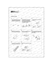
Recessed - Bracket Installation
Fixing Centres (per fitting)
1.0m
1.5m
2.0m
700mm
2700mm + centre fixing
3.0m
1200mm
1700mm
IMPORTANT: Once brackets
are fully installed. Plaster surface
before installing the Leat.
a)
Cut aperture to required size.
Using the flat bracket (sold separately) as a drilling template, drill 4 x holes
5mm dia, through pilot holes. See ‘Bracket Orientation’.
Counter sink the drilled holes so c/sk screws (supplied) sit flush with
the plasterboard.
Aperture
Trim - 65.5mm wide
Trimless - 57.0mm wide
Fixing crs
Dimn ‘a’
Drilling Direction
240mm MAX
Plasterboard
160mm MIN
44x44mm
Wooden
Battens
Recommended Wooden Batten Spacing
For Plasterboard Support
Drilling Direction
b)
Secure each slider to
plasterboard using M5
c/sk screws supplied
Dim ‘a’
Trimmed
Trimless
79.0mm
76.0mm
Bracket Orientation
When using the flat bracket for the drill hole locations make sure the metalwork is
in the correct orientation.
The image on the left shows the orientation for the trimless variant and the image on
the right shows the orientation for the trimmed version.
c)
Fold flat bracket over and fix spring clip.
Fit main bracket into slider brackets. Ensure that
dimension ‘a’ from bottom of plasterboard to the inside
face of main face is adhered to. Tighten slider
bracket screws to hold main bracket in place.
Dim ‘a’

Instruction Manual - K1121V3
July 2018
Leat
Fi
x
i
n
g C
ent
re
s
Suspension Ceiling Fixing
Fix ceiling boss
mounting surface
using suitable
wood screw
Feed 1-5m long wire
into body as shown
- screw body into
ceiling boss
a) Follow procedures ‘a’ to ‘c’ as per ‘Surface
Bracket Installation’.
b) Fix suspension wire to surface (see ‘Suspension
Ceiling Fixing’).
c) locate the suspension wire thread through
the central surface bracket hole, and secure
with supplied M4 nut supplied. Offer the
Leat up to the surface brackets and fix
Suspension Wire Installation
3
c) Disconnect the connecting block
from the geartray to the housing.
Then fully remove the geartray.
a) Remove diffuser using the
suction cup (supplied) positioned
at the centre of the diffuser.
(Stand alone only)
b) Using a screwdriver, gently
disengage the geartray using
the slotted tabs
Fixing Centres
1.0m
1.5m
2.0m
700mm
2700mm + central fixing
3.0m
1200mm
1700mm
d) Once spring clips are secure, fix housing into the spring clips.
Ensure the spring clips are located above the 21mm diameter
holes in the back of the housing, for future removal.
(see table for hole locations).
e) Wire (as shown in section 4)
supply cable into luminaire,
re-connect the connecting
block and fix geartray and
diffuser back into place
2
Surface Bracket Installation
IMPORTANT DO NOT REMOVE ENDCAPS

Instruction Manual - K1121V3
July 2018
Leat
Safe Operation
1. Check the rating label for voltage and frequency before connecting this
luminaire to the
electrical supply.
2. Ensure that the mains supply is switched off when working on this
luminaire, whether
installing or carrying out any other servicing.
3. Do not mount luminaire on or close to readily flammable materials.
4. To prevent damage to driver, do not mix with conventional magnetic
ballasts on the same
electrical circuit.
5. Where use in more onerous situations is required, e.g. In part-
completed buildings before
“drying-out” is completed, or areas where ambient temperatures are
outside the normal
temperature range, then consult our Sales Office.
6. The light source contained in this luminaire shall only be replaced by the
manufacturer or his
service agent or a similar qualified person.
7. When used as intended this product complies with the EMC Directive
2014/30/EU and Low
Voltage Directive 2014/35/EU.
Servicing and Disposal
1. At commissioning and handing over of installation ensure that a copy of
these instructions is
presented to the authority responsible for the operation and
maintenance of the luminaries.
2. Servicing, e.g. cleaning, must only be carried out after the electricity
supply has been
switched off. It must not be assumed that luminaries with LEDs not lit
are switched off ,
always check before servicing.
3. Cleaning should be carried out at regular intervals to ensure that dirt
does not accumulate to
an extent that will impair the thermal safety or optical performance of
the luminaire. Regular
cleaning will also ensure that the optical performance of the luminaries
is maintained.
4. Avoid touching the LED array surface. To clean - Blow surface with
either dry air or nitrogen
gas.
5. At the end of life the luminaire is classed as WEEE under directive
2012/19/EU and should
be disposed of in accordance with local legislation.
Continuous Installation
Start of Run
Cable Entry
Fit LEAEC - one endplate
per start and end of run
Diffuser
a) Follow procedures ‘a’ to ‘c’ as per
‘Surface Bracket Installation’.
b) Install desired fixing method
(recessed, surface or suspended)
and wire.
c) Fix both leat housings using the
Connector plates
d) Wire connecting block (see bottom right) from
the incoming Leat and connect to the Leat
previously installed.
RED - Dali (+/-)
WHITE - Dali (+/-)
Unused
BLACK - Live Unswitched
BROWN - Live Switched
GREEN/YELLOW - Earth
BLUE - Neutral
N 1
2
3 + -
e) Fix geartray clamp into
the geartray at the start of the run
and fix in place. Then fix the next
geartray , locating it in the clamp.
Repeat the process for any additional Leats.
f) Once geartrays have been installed
feed the diffuser down one end of the run and
cap off at the ends of the first and last Leat.
Geartray Clamp
4
5
Wiring
D1
D2
L3N L2
L1
LUMINAIRE MUST BE EARTHED
ISOLATE MAINS SUPPLY BEFORE WIRING
Trim Installation
1
2
6
1) Offer trim up to
the edge of the
Leat housing.
2) Once located, tighten
grub screws with
a 2mm allen key.
RED - Dali (+/-)
WHITE - Dali (+/-)
Unused
BLACK - Live Unswitched
BROWN - Live Switched
GREEN/YELLOW - Earth
BLUE - Neutral
D1 -
D2 -
L3 -
L2 -
L1 -
-
N -
Side view
of the trim
fully installed
Housing
Trim
Grub Screw
2
NOTE: Solid core only. Max 2.5mm
Luminaire Service Luminaire CleaningEnd of Life and Components Disposal
WEEE
First slide the connecting plates into housing,
sitting the bottom of the plate in the small
channel. Fix plate in position with supplied
screw (Do not over tighten). Connect the next
housing onto the plate and secure.
Connector Plates

K1121V3
Eaton
Wheatley Hall Road, Doncaster, South Yorkshire, DN2 4NB
Sales
T: +44 (0)1302 303303
F: +44 (0)1302 367155
E: sales@cooper-ls.com
General
+44 (0)1302 321541
+44 (0)1302 303220
technical@cooper-ls.com
International Sales
+44 (0)1302 303250
+44 (0)1302 303251
export@cooper-ls.com
/