Texas Instruments Designing Fault Protection Circuits Using Wide VIN LM5121 Application notes
- Category
- Rechargeable batteries
- Type
- Application notes

Application Report
SNVA726–January 2015
Designing Fault Protection Circuits Using Wide VIN
LM5121
Eric Lee and Daniel Braunworth
ABSTRACT
Battery powered systems or systems with low input voltage supplies may have loads that require higher
voltage outputs. A boost converter is a usual choice for non-isolated applications; however, boost
converters do not naturally provide system protection to downstream circuitry due to the pass path from
input to output. Problems due to this pass path are now resolved with the LM5121 boost controller which
is designed with a wide input operating range and fault protection features to address systems that
experience harsh inputs or load faults. The built-in input disconnect switch control provides inrush limit,
output short circuit protection and circuit breaker functions. This application report explores the
implementation of and component selection for the protection circuits enabled by LM5121 using its input
disconnect switch control feature. This enables inrush protection, output short circuit protection, and circuit
breaker functionality. Additional input fault circuit applications and reverse battery protection are also
discussed.
Contents
1 Introduction ................................................................................................................... 2
2 How The Inrush Control Works ........................................................................................... 2
3 How The Hiccup Mode Output Short Circuit Protection Works ....................................................... 4
4 How The Circuit Breaker Works ........................................................................................... 5
5 Disconnect MOSFET Selection............................................................................................ 6
6 Freewheeling Diode Selection ............................................................................................. 7
7 Conclusion.................................................................................................................... 7
8 Appendix A: Inrush Current Limit Programming......................................................................... 8
9 Appendix B: Input Over-Voltage Transient Protection .................................................................. 9
10 Appendix C: Reverse Battery Protection................................................................................ 10
11 References.................................................................................................................. 11
1
SNVA726–January 2015 Designing Fault Protection Circuits Using Wide VIN LM5121
Submit Documentation Feedback
Copyright © 2015, Texas Instruments Incorporated

VCC
LM5121
CSN
DG
SYNCIN/RT
RES
SS
UVLO
VIN
AGND
BST
MODE
PGND
SLOPE
COMP
FB
HO
LO
SW
+
DS
V
OUT
V
IN
CSP
Introduction
www.ti.com
1 Introduction
Aside from the core boosting function, the purpose of LM5121 is to provide fault protection that would
otherwise be designed discretely or with a separate hot swap type controller. Flexible protection control is
integrated with the boost converter to simplify the design. Various fault protection schemes can be
achieved including load disconnection, inrush current limiting, hiccup mode short circuit protection, circuit
breaker, and input over-voltage transient suppression.
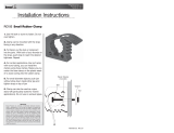
Figure 1 shows the complete schematic of an LM5121 synchronous boost controller with the additional
current sense resistor and disconnect FET required for the basic protection control. The following sections
will detail the operation of each system-level protection mode and component selection considerations.
The appendix expands to share application examples that enable more complex protection like over-
voltage transient and reverse polarity protection with simple circuit modifications.
Figure 1. LM5121 Synchronous Boost Controller with Disconnect Switch
2 How The Inrush Control Works
Large output capacitors (C
OUT
) in the boost converter can cause an excessive inrush current during the
initial charging. The sense resistor (R
S
), inductor (L
IN
), and high-side switching device (Q
H
) can be
damaged by this excessive inrush current.
Solutions to control the amount of inrush current include slowly increasing the input supply voltage (V
IN
),
placing a NTC thermistor, or employing a dedicated hot-swap controller ahead of the boost. But these
options require external circuitry, adding cost and increasing total solution size. Especially, an NTC
thermistor drops system efficiency, increases board temperature, and does not handle repetitive fault
events. The LM5121 boost controller has an integrated inrush current limit circuit which removes the need
of dedicated hot-swap or NTC thermistor.
LM5121’s internal charge pump turns on when the UVLO pin voltage is greater than the UVLO threshold
of 1.2 V. The charge pump is sourced from the VIN pin and sources 25 uA current at the DG pin to
enhance an N-channel MOSFET disconnect switch (Q
D
).
An internal high-side current sense amplifier senses the voltage across the sense resistor. When the
sensed current reaches the 1.1 V inrush current limit threshold (V
CS-TH2
), the DG pin voltage (V
G
) is
controlled to limit the current flow in the sense resistor by controlling DG current sink.
2
Designing Fault Protection Circuits Using Wide VIN LM5121 SNVA726–January 2015
Submit Documentation Feedback
Copyright © 2015, Texas Instruments Incorporated

1.1 V
Q
D
+
±
AMP
Inrush Current Limiter
VIN
+
±
CSN
CS
AMP
CSP
A=10
R
S
VIN DS
25-
µ
A
DG Charge Pump
Source
Load
DG
11-
V Zener Diode
Gm
=
1
.
2
µ
A
/
mV
www.ti.com
How The Inrush Control Works
Figure 2. Inrush Current Limit Circuit
The waveform in Figure 3 shows typical inrush current limiting and Figure 4 shows normal startup
sequence. As the operating point of the disconnect switch transitions from cut-off to the ohmic region by
increasing the gate voltage, the source voltage of the disconnect switch (V
S
) is also increased and the
drain-to-source voltage (V
DS
) of the disconnect switch decreases as a result. During this initial output
capacitor charging period, controlling the gate-to-source voltage (V
GS
) of the disconnect switch limits the
inrush current. After fully charging up the output capacitors, the amount of inrush current drops
dramatically and the gate-to-source voltage increases by the 25 uA DG sourcing current again since the
DG current sink turns off. LM5121 will start its soft-start procedure once the gate-to-source voltage rises
above the gate-to-source voltage detection threshold (V
GS-DET
) of 5.4 V.
Figure 3. Inrush Current Limit Waveform (C1: V
DS
, C3: I
D
, C4: V
GS
, F1: P
QD
=V
DS
x I
D
)
3
SNVA726–January 2015 Designing Fault Protection Circuits Using Wide VIN LM5121
Submit Documentation Feedback
Copyright © 2015, Texas Instruments Incorporated

RESTART
TIMER
RES
30 µA
10 µA
5 µA
C
RES
D
RES
(
optional
)
V
GS
Detect
VCC UVLO
threshold
V
GS
Inrush
current
limit
TURN-OFF
TURN-ON
0.4 V
1.2 V
UVLO
VOUT
SS
LO
VCC
V
GS
detection th.
1.2 V
HO-SW
Startup Delay
Shut down
Standby
t
SS
V
IN
How The Hiccup Mode Output Short Circuit Protection Works
www.ti.com
Figure 4. Start-Up Sequence
The DG pin voltage is clamped by an internal 11 V zener diode which is connected from the DG pin to the
VIN pin. The VIN pin voltage is allowed to be higher or lower than the input supply voltage when an
external bias supply is available for the LM5121. The external VIN pin voltage should be carefully selected
since the effective gate-to-source voltage of the disconnect switch is decreased when the VIN pin voltage
is lower than the input supply voltage.
See Section 8 for further discussion on programming the inrush current limit.
3 How The Hiccup Mode Output Short Circuit Protection Works
All non-synchronous and synchronous boost converters have a direct path from the source to the load
through the high-side switching device. Due to this direct path, there is no way to isolate an output short-
circuit fault from the input power source. This absence of output short circuit protection in boost converters
demands the use of a fuse in front of the converter for input supply protection.
LM5121 provides hiccup mode output short circuit protection using the disconnect switch. During the
hiccup mode operation, LM5121 repeatedly turns off for a given time and then restarts. Figure 5 and
Figure 6 show a hiccup mode restart timer programming circuit and the sequence of the hiccup operation.
Figure 5. Hiccup Mode Restart Timer Programming Circuit
4
Designing Fault Protection Circuits Using Wide VIN LM5121 SNVA726–January 2015
Submit Documentation Feedback
Copyright © 2015, Texas Instruments Incorporated

4 V
2.0 V
1.2 V
Count to Eight
RES
I
RES
= 30 µA
I
RES
= 10 µA I
RES
= ±5 µA
V
GS-DET
RES Delay
t
RD
Hiccup Mode Off-time
t
RES
V
DG-DS
I
LIN
RES
RD
C 1.2
t [s]
30
u
P
www.ti.com
How The Circuit Breaker Works
During normal operation, the timer’s normal-state 5 uA discharging current pulls down the RES pin voltage
to the ground. If a cycle-by-cycle current limit or inrush current limit is reached, a 30 uA RES fault-state
charging current (I
RES-SOURCE1
) charges the RES capacitor (C
RES
). If the RES pin voltage exceeds the 1.2 V
restart threshold after the RES delay in Figure 6 (t
RD
), a hiccup mode restart sequence is initiated. The
RES delay time can be calculated as follows:
(1)
During the hiccup mode off-time (t
RES
), switching stops and the DG pin is discharged to ground if the
inrush current limit is reached. The RES pin voltage ramps up and down between 2 V and 4 V eight times
via a 10 µA RES hiccup mode off-time charging current (I
RES-SOURCE2
) and 5 uA hiccup mode off-time
discharging current (I
RES-SINK2
).
After the eight cycles, the inrush current limiting is reactivated, the DG pin is released and charged by the
25 µA DG sourcing current again.
Figure 6. Hiccup Mode Restart Sequence
The ratio between the RES delay (t
RD
) and hiccup mode off-time is typically 122 and internally set. The
total off-time should be programmed to allow enough time to cool down the switch under repetitive restart
operation.
By connecting a zener diode (D
RES
) to the RES pin with characteristics of a sharp knee, 2.4 V to 3.6 V
breakdown, and low reverse leakage, the LM5121 will disable the hiccup mode and latch off until reset.
The reverse leakage current at 1.2 V should be smaller than the RES fault-state charging current of 10 uA
(I
RES-SOURCE2
).
4 How The Circuit Breaker Works
High reliability and robust system design requires ensuring safety in all circumstances. A front-end fuse is
often required to mitigate further system damage in a gross fault condition; however, LM5121 provides a
circuit breaker function in addition to the hiccup mode protection to add a failsafe disconnect in place of a
front end fuse. If the sensed current increases rapidly due to a fault, the current may exceed the inrush
current control threshold before the inrush control loop responds. If the sensed current exceeds the 1.6 V
circuit breaker threshold (V
CS-TH3
), a fast-response internal pull down switch quickly discharges the DG pin
until the sensed current falls below the 0.11 V circuit breaker disable threshold (V
CS-TH4
), and then
reactivates the inrush current limiting.
5
SNVA726–January 2015 Designing Fault Protection Circuits Using Wide VIN LM5121
Submit Documentation Feedback
Copyright © 2015, Texas Instruments Incorporated

CS TH2
INRUSH
S
V
I [A]
R
2
OUT IN(MAX)
INRUSH
C V
E [J]
2
u
Q
D
+
±
CSN
CS
AMP
CSP
A=10
R
S
VIN DS
Source
Load
DG
16-
V Zener Diode
Circuit Breaker Comparator
1.6 V / 0.11 V
+
±
38
Disconnect MOSFET Selection
www.ti.com
Figure 7. Circuit Breaker Circuit
In addition to the internal 11 V zener clamp from the DG pin to the VIN pin, the DG pin voltage is also
clamped by a 16 V zener diode which is connected from DG pin to DS pin. This 16 V zener diode helps
the DG-to-DS voltage not to exceed the MOSFET’s gate-to-source break down voltage and limits the DG
pin voltage from falling below one diode drop of the DS pin voltage when the circuit breaker activated.
5 Disconnect MOSFET Selection
The N-Channel MOSFET disconnect switch should be carefully selected to ensure that LM5121 provides
adequate protection without allowing any damage to the MOSFET during the various protection modes.
Choose a MOSFET whose drain-to-source breakdown voltage (BV
DS
) is higher than the maximum input
supply voltage plus ringing and transients. The continuous drain current (I
D-CONTINUOUS
) should be high
enough to handle the full load input current at the minimum input supply voltage. Choosing a MOSFET
whose gate-to-source breakdown voltage (B
VGS
) is +/-20 V or greater is recommended since the 16 V
internal zener diode clamps the maximum gate-to-source voltage to 16 V. The miller plateau voltage
(V
PLATEAU
) should be less than the 11 V zener clamp voltage and is recommended to be less than the gate-
to-source voltage detection threshold (V
GS-DET
) of 5.4 V.
If the miller plateau voltage is greater than the gate-to-source voltage detection threshold, LM5121 might
start its soft-start procedure before the inrush current limiting is finished since the MOSFET will not be fully
enhanced until the gate voltage reaches the miller plateau. In this case, switching could start before V
OUT
reaches VIN. Refer to Figure 4 for normal startup operation when the miller plateau is below V
GS-DET
.
If the VIN pin voltage is less than 6.5 V, a logic level MOSFET should be selected since the strength of
the DG charge pump is proportional with the VIN pin voltage.
It is okay for the disconnect switch to have a large gate input capacitance (C
iss
) since a slow turn on helps
to minimize the amount of the inrush current. Insufficient gate-to-source capacitance can cause the gate-
to-source voltage to oscillate during inrush current limiting, but an additional external gate-to-source
capacitor helps if a lower C
iss
MOSFET is selected.
To survive during the output capacitor charging period, the disconnect switch should be capable of
handling the energy to charge the output capacitor up to the input supply voltage. This can be checked by
comparing the required energy for output charging with the avalanche energy rating of MOSFET or by
checking the safe operating area (SOA) graph in the MOSFET datasheet. The maximum output capacitor
charging energy is calculated as follows:
(2)
To survive during an output short circuit condition, a more rugged MOSFET is required than calculated
based on inrush current limiting. The disconnect switch should be able to handle the maximum inrush
current during the RES delay time at the maximum input supply voltage. The amount of controlled inrush
current is calculated as follows:
(3)
6
Designing Fault Protection Circuits Using Wide VIN LM5121 SNVA726–January 2015
Submit Documentation Feedback
Copyright © 2015, Texas Instruments Incorporated

IN
DF
S OUT IN(MIN)
L 0.16
t [s]
R V V
u
u
IN(MAX) CS TH3 RES
CB
S RES SOURCE1
V V C 1.2
E [J]
R I
u u u
u
IN(MAX) CS TH2 RES
SHORT
S RES SOURCE1
V V C 1.2
E [J]
R I
u u u
u
RD RES
RES SOURCE1
1.2
t C [s]
I
u
IN
INRUSH OUT
INRUSH LOAD STARTUP
V
t C [s]
I I
u
www.ti.com
Freewheeling Diode Selection
The RES delay time should be longer than the time which is required to charge the output capacitor. The
duration to charge the output capacitor up to the input supply voltage is:
(4)
where I
LOAD-STARTUP
is a preload which exists before fully turning on the boost converter.
From Figure 6 the RES delay time is calculated as follows:
(5)
where I
RES-SOURCE1
is the RES pin fault state charging current which is typically 30 uA.
The required capability to survive during the output short condition is calculated as follows:
(6)
The necessary condition to survive when the circuit breaker is tripped is the harshest condition discussed
here and requires a stronger MOSFET than calculated based on short circuit condition. To survive when
the circuit breaker is tripped, the switch should be able to handle the energy calculated as follows:
(7)
Since the ratio between the RES delay and the hiccup mode off-time is 122, this should be enough time to
cool down the switch in a repetitive restart condition, but the single pulse avalanche energy rating of the
switch should be derated if a design is not thermally optimized. If the repetitive avalanche characteristic is
not enough to handle the necessary energy during the repetitive hiccup operation, improve the thermal
dissipation using a heat-sink or enable the latch-off mode short circuit protection by connecting the 2.4 V
to 3.6 V rated zener diode (D
RES
) at RES pin. Since a bigger package MOSFET generally has a larger
SOA and better thermal dissipation, select the MOSFET as large as is reasonable for the design.
6 Freewheeling Diode Selection
A freewheeling diode (D
F
) should be placed between the disconnect switch and the inductor. Please refer
to Figure 9. This diode conducts only when the disconnect switch turns off quickly, especially in the circuit
breaker scenario. If the switch turns off quickly when the inductor current flows, the inductor current
continues flowing through this freewheeling diode. The diode should be able to handle 160 mV/Rs of peak
current while the inductor current decays, and the voltage rating of the diode must be greater than the
maximum input supply voltage, plus ringing and transients. The inductor current decaying time (t
DF
) is
calculated as follows:
(8)
7 Conclusion
With good understanding of the line and load conditions that the boost circuit must survive, these
protection features enable a robust design that minimizes front-end circuitry and system reliability
concerns. Inrush control will ensure that supplies are not overdrawn on startup. Output short circuit
protection protects the system from over-driving a load fault, and the hiccup mode gives a retry
opportunity for transient problems without requiring a full system restart. Circuit breaker functionality offers
a fast-response and second level of protection from over-current events. While designing for these
conditions, careful attention should be paid to the protection component selection to ensure a robust
design.
The following appendices give more protection circuit examples including additions to achieve input over-
voltage protection and input reverse polarity protection. Modifications for decreasing the inrush current
limit for slow startup charging are also detailed.
7
SNVA726–January 2015 Designing Fault Protection Circuits Using Wide VIN LM5121
Submit Documentation Feedback
Copyright © 2015, Texas Instruments Incorporated

CS TH2 IN(MAX)
INRUSH
INRUSH2
S
100
V V
100 R
I [A]
R
§ ·
u
¨ ¸
© ¹
CSNCSP
R
S
VCC
SLOPE
100
100
100 k
R
INRUSH
I
LIN
Appendix A: Inrush Current Limit Programming
www.ti.com
8 Appendix A: Inrush Current Limit Programming
To enable a controlled startup inrush that is less than the normal operating current limit, the SLOPE pin
can be used to program the inrush current limit to a lower level than the cycle-by-cycle current limit. The
SLOPE pin is internally grounded under any fault conditions and at startup, which can be used to modify
the current limit in those cases. Otherwise, the SLOPE pin voltage is regulated at 1.2 V only when the
gate-to-source voltage of the disconnect switch is greater than the gate-to-source voltage detection
threshold (V
GS-DET
) of 5.4 V in normal operation. Normal condition is when the UVLO pin is greater than 1.2
V, VCC voltage is greater than the 4.0 V VCC UVLO threshold, the RES pin voltage is lower than 1.2 V,
and there is no thermal shutdown and no circuit breaker operation.
Figure 8. Inrush Current Limit Programming
By adding the inrush programming circuit in Figure 8, the new inrush current limit level can be calculated
as follows:
(9)
8
Designing Fault Protection Circuits Using Wide VIN LM5121 SNVA726–January 2015
Submit Documentation Feedback
Copyright © 2015, Texas Instruments Incorporated

OUT CLAMP ZENER GS TH
V V V [V]
CSN DG DSCSP
V
IN
D
F
L
IN
D
G
www.ti.com
Appendix B: Input Over-Voltage Transient Protection
9 Appendix B: Input Over-Voltage Transient Protection
Input over-voltage transient suppression can be easily achieved by adding a zener diode from the DG pin
to ground.
Figure 9. Input Over Voltage Transient Protection
Since the DG pin voltage is clamped to the selected zener voltage (V
ZENER
) and the N-channel MOSFET
turns off when the gate-to-source voltage is lower than the gate threshold voltage, the DS pin voltage is
also clamped. The output clamping voltage is calculated as follows:
(10)
Since the disconnect switch operates in the ohmic region during the input over-voltage transient
protection, the disconnect MOSFET should be carefully selected, taking into account the safe operating
area. The maximum allowable clamping time will be limited by the property of the MOSFET.
9
SNVA726–January 2015 Designing Fault Protection Circuits Using Wide VIN LM5121
Submit Documentation Feedback
Copyright © 2015, Texas Instruments Incorporated

VCC
LM5121
CSN
DG
SYNCIN/RT
RES
SS
UVLO
VIN
AGND
BST
MODE
PGND
SLOPE
COMP
FB
HO
LO
SW
+
DS
V
OUT
CSP
V
IN
+
500 k
Power
NMOS
Signal
PMOS
500 k
100 pF
Appendix C: Reverse Battery Protection
www.ti.com
10 Appendix C: Reverse Battery Protection
Reverse battery protection prevents damage to downstream circuitry in the event of supply connected into
incorrect polarity. LM5121’s disconnect switch control can be used to enhance an N-channel reverse
battery blocking MOSFET. In Figure 10, the power NMOS acts as a natural disconnect switch when a
negative Vin voltage keeps the gate discharged. When the battery is properly installed, the signal PMOS
turns on and passes the DG sourcing current to the gate of the power NMOS. Power is delivered to the IC
through the body diode of the NMOS during startup until the DG sourcing current comes up and enhances
the NMOS gate.
Figure 10. Reverse Battery Protection Circuit
10
Designing Fault Protection Circuits Using Wide VIN LM5121 SNVA726–January 2015
Submit Documentation Feedback
Copyright © 2015, Texas Instruments Incorporated

www.ti.com
References
11 References
LM5121 Wide Input Synchronous Boost Controller with Disconnect Switch Control (SNVS963)
LM5122 Wide Input Synchronous Boost Controller with Multi Phase Capability (SNVS954)
LM5060 High-Side Protection Controller with Low Quiescent Current (SNVS628)
CSD19536KCS 100 V N-Channel NexFET™ Power MOSFET (SLPS485)
11
SNVA726–January 2015 Designing Fault Protection Circuits Using Wide VIN LM5121
Submit Documentation Feedback
Copyright © 2015, Texas Instruments Incorporated


IMPORTANT NOTICE
Texas Instruments Incorporated and its subsidiaries (TI) reserve the right to make corrections, enhancements, improvements and other
changes to its semiconductor products and services per JESD46, latest issue, and to discontinue any product or service per JESD48, latest
issue. Buyers should obtain the latest relevant information before placing orders and should verify that such information is current and
complete. All semiconductor products (also referred to herein as “components”) are sold subject to TI’s terms and conditions of sale
supplied at the time of order acknowledgment.
TI warrants performance of its components to the specifications applicable at the time of sale, in accordance with the warranty in TI’s terms
and conditions of sale of semiconductor products. Testing and other quality control techniques are used to the extent TI deems necessary
to support this warranty. Except where mandated by applicable law, testing of all parameters of each component is not necessarily
performed.
TI assumes no liability for applications assistance or the design of Buyers’ products. Buyers are responsible for their products and
applications using TI components. To minimize the risks associated with Buyers’ products and applications, Buyers should provide
adequate design and operating safeguards.
TI does not warrant or represent that any license, either express or implied, is granted under any patent right, copyright, mask work right, or
other intellectual property right relating to any combination, machine, or process in which TI components or services are used. Information
published by TI regarding third-party products or services does not constitute a license to use such products or services or a warranty or
endorsement thereof. Use of such information may require a license from a third party under the patents or other intellectual property of the
third party, or a license from TI under the patents or other intellectual property of TI.
Reproduction of significant portions of TI information in TI data books or data sheets is permissible only if reproduction is without alteration
and is accompanied by all associated warranties, conditions, limitations, and notices. TI is not responsible or liable for such altered
documentation. Information of third parties may be subject to additional restrictions.
Resale of TI components or services with statements different from or beyond the parameters stated by TI for that component or service
voids all express and any implied warranties for the associated TI component or service and is an unfair and deceptive business practice.
TI is not responsible or liable for any such statements.
Buyer acknowledges and agrees that it is solely responsible for compliance with all legal, regulatory and safety-related requirements
concerning its products, and any use of TI components in its applications, notwithstanding any applications-related information or support
that may be provided by TI. Buyer represents and agrees that it has all the necessary expertise to create and implement safeguards which
anticipate dangerous consequences of failures, monitor failures and their consequences, lessen the likelihood of failures that might cause
harm and take appropriate remedial actions. Buyer will fully indemnify TI and its representatives against any damages arising out of the use
of any TI components in safety-critical applications.
In some cases, TI components may be promoted specifically to facilitate safety-related applications. With such components, TI’s goal is to
help enable customers to design and create their own end-product solutions that meet applicable functional safety standards and
requirements. Nonetheless, such components are subject to these terms.
No TI components are authorized for use in FDA Class III (or similar life-critical medical equipment) unless authorized officers of the parties
have executed a special agreement specifically governing such use.
Only those TI components which TI has specifically designated as military grade or “enhanced plastic” are designed and intended for use in
military/aerospace applications or environments. Buyer acknowledges and agrees that any military or aerospace use of TI components
which have not been so designated is solely at the Buyer's risk, and that Buyer is solely responsible for compliance with all legal and
regulatory requirements in connection with such use.
TI has specifically designated certain components as meeting ISO/TS16949 requirements, mainly for automotive use. In any case of use of
non-designated products, TI will not be responsible for any failure to meet ISO/TS16949.
Products Applications
Audio www.ti.com/audio Automotive and Transportation www.ti.com/automotive
Amplifiers amplifier.ti.com Communications and Telecom www.ti.com/communications
Data Converters dataconverter.ti.com Computers and Peripherals www.ti.com/computers
DLP® Products www.dlp.com Consumer Electronics www.ti.com/consumer-apps
DSP dsp.ti.com Energy and Lighting www.ti.com/energy
Clocks and Timers www.ti.com/clocks Industrial www.ti.com/industrial
Interface interface.ti.com Medical www.ti.com/medical
Logic logic.ti.com Security www.ti.com/security
Power Mgmt power.ti.com Space, Avionics and Defense www.ti.com/space-avionics-defense
Microcontrollers microcontroller.ti.com Video and Imaging www.ti.com/video
RFID www.ti-rfid.com
OMAP Applications Processors www.ti.com/omap TI E2E Community e2e.ti.com
Wireless Connectivity www.ti.com/wirelessconnectivity
Mailing Address: Texas Instruments, Post Office Box 655303, Dallas, Texas 75265
Copyright © 2015, Texas Instruments Incorporated
-
 1
1
-
 2
2
-
 3
3
-
 4
4
-
 5
5
-
 6
6
-
 7
7
-
 8
8
-
 9
9
-
 10
10
-
 11
11
-
 12
12
-
 13
13


Texas Instruments Designing Fault Protection Circuits Using Wide VIN LM5121 Application notes
- Category
- Rechargeable batteries
- Type
- Application notes
Ask a question and I''ll find the answer in the document
Finding information in a document is now easier with AI
Related papers
-
Texas Instruments Reverse Battery Protection with the TPS27081A Application notes
-
-
-
-
-
-
-
-
-
Other documents
-
Magnadyne VCS-10 Installation guide
-
 Buyers Products RC105 Owner's manual
-
Microchip Technology MIC2125 General Description Manual
-
Delta Electronics Delphi ND Series User manual
-
NXP TEA1720BT User guide
-
Fairchild SEMICONDUCTOR RC5042 User manual
-
-
-
Analog Devices ADP1873-EVALZ User manual
-
Grisham 90002 Measurement Guide
