Page is loading ...

12.0973.0004
ROTRONIC AG, CH-8303 Bassersdorf
Tel. +41 44 838 11 44, www.rotronic.com
ROTRONIC Messgeräte GmbH, D-76275 Ettlingen
Tel. +49 7243 383 250, www.rotronic.de
ROTRONIC SARL, 56, F - 77183 Croissy Beaubourg
Tél. +33 1 60 95 07 10, www.rotronic.fr
ROTRONIC Italia srl
, I- 20157 Milano
Tel. +39 2 39 00 71 90, www.rotronic.it
ROTRONIC Instruments (UK) Ltd, West Sussex, RH10 9EE
Phone +44 1293 571000, www.rotronic.co.uk
ROTRONIC Instrument Corp, NY 11788, USA
Phone +1 631 427-3898, www.rotronic-usa.com
ROTRONIC Instruments Pte. Ltd., Singapore 159836
Phone +65 6376 2107, www.rotronic.sg
ROTRONIC Shanghai Rep. Office, Shanghai 200233, China
Phone +86 40 0816 2018, www.rotronic.cn
ROTRONIC Canada Inc., Canada L8W 3P7
Phone+ 1 905 754 5164, www.rotronic.ca
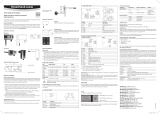
4-wire circuit / HF56x
AC
DC
AC L
AC N
OUT
2
OUT
1
GND
AC
DC
AC L
AC N
OUT
2
OUT
1
GND
O
O
A
Digital & analogue Transmitter for Humidity & Temperature
Wall Version
Congratulations on the purchase of your new HygroFlex5-series transmitter. You have bought a
state-of-the-art device. Please read these short instructions carefully before installing the device.
General Description
The HygroFlex5-series devices are universal transmitters for transmission of humidity and tempe-
rature measurements. These short instructions are limited to a description of the main functions
and installation of the device. The detailed instruction manual can be found on the internet at:
www.rotronic.com.
Dimensions / Connections
Mechanical Installation
Wall Version (Type W)
General Recommendations
Relative humidity is extremely temperature-dependent. In order to measure it exactly, the probe and
sensors must be set exactly on the temperature level of the environment that is to be measured.
Follow the guidelines below to ensure optimum performance:
a) Choose a representative position for installation:
Install the probe at a place where the humidity, temperature and pressure conditions are
representative of the environment that is to be measured.
an air velocity of at least 1 meter per second accelerates and facilitates adaptation of the probe
to changing temperatures.
c) Avoid:
1. Probe too close to heating elements, cooling coils, cold or hot walls, direct sunlight, etc.
3. Unstable pressure conditions with high air turbulence.
d) Insert the probe as far as possible into the environment that is to be measured.
e) Avoid accumulation of condensation at the contact wires of the sensor.
Install the probe such that the probe tip points down. If that is not possible, install it in
horizontal position.
Maintenance
a) The device must not come into contact with liquids.
b) Clean the outside of the device by wiping with a moist cloth.
Mounting the Wall Version
Orientation
Mount the transmitter so that the probe points down.
Mounting Variant 1 (Drill Template)
Drill the necessary holes using the drill template drawn on the
packaging. Then insert the plugs delivered with the device and
mount the transmitter with the screws.
Mounting Variant 2 (DIN Top-Hat Rail)
If there is a TS35 DIN top-hat rail available, the transmitter can be
clipped on to the top-hat rail directly with the help of the mounting kit
AC5002 (available as optional extra). The DIN holders (one package
unit contains 2 holders and 8 screws) are screwed directly on to the
pre-drilled holes of the transmitter for this.
Electrical Installation
Power Supply
4-wire with analog outputs: 100 to 240 VAC.
With both output circuits closed, the maximum current consumption is 50 mA.
Supply Voltage / Technology
Type Supply Voltage V+ Load Output
4-wire
HF561 100…240 VAC Max. 500 Ω 0...20 mA (<15 V)
HF562 100…240 VAC Max. 500 Ω 4...20 mA (<15 V))
HF563 100…240 VAC Min. 1000 Ω 0...1 V
HF564 100…240 VAC Min. 1000 Ω 0...5 V
HF565 100…240 VAC Min. 1000 Ω 0...10 V
Caution: Please follow the instructions in the user guide. Wrong supply voltages and
excessive loads on the outputs can damage the transmitter.
The device must be installed by a skilled electrician.
A suitable power connection cable must be used:
- Recommended power cable H05 V V-F Helukabel
- Power & signal cable Ø 6-8 mm
- Max. wire cross section 2.5 mm
2
- Tightening torque 3-5 Nm
It must not be possible to loosen the cable glands again by hand after installation.
The device does not have a mains power switch. This switch must be provided outside
the device at an accessible point and marked accordingly.
The device is only safe if the information and instructions in the manual are followed.
Caution: The connections OUT1, OUT2, GND, D+ and D– as well as the USB and Ethernet
connections may only be connected with adequate separate secondary current cir-
cuits. The terminals OUT1, OUT2, GND, D+ and D– may not be connected with mains
power supply. Make sure that everything has been connected correctly and that all
settings have been made correctly before integrating and connecting the transmitter
in the network.
Programming
The initial settings of the units are made in the factory to your order. The transmitters are adjusted
in the factory, so checking and readjustment at installation time are not necessary. The units can
be put into operation immediately after installation.
Display
when a button is pressed.
It is possible to change between a two-line or three-line display by pressing the Enter button.
+
:
Increase value / Display line up
–
:
Decrease value / Display line down
When there is an alarm, "Sensor Alarm" is shown at the bottom display edge.
It is possible to choose between metric or English system units.
MENU button
Open / Close menu
ENTER button
Select menu point
Menu Navigation
Buttons + / – change va-
lue increase / decrease
Note: Unauthorized use of the menu can be prevented by locking the setting “Display Menu”
(using the HW4 software > Device Manager > Display).
Sources of Error
Temperature Errors
Adaptation time too short, cold outside wall, heating elements, sunlight, etc.
Humidity Errors
Through vapor, splashed water, dripping water or condensation on the sensor, etc. This does not,
however, impair reproducibility or long-term stability, even when the sensor is exposed to high
humidity or saturation with water vapor (condensation) for a prolonged period.
Contamination
Scaling / Adjustment / Firmware Update
The following settings can be made using the HW4 software and AC3006 or AC3009 service cable:
• rescaling of the outputs
• adjustment
www.rotronic.com.
Periodical Calibration of the Sensor / Transmitter
Both the Pt 100 RTD temperature sensor and the associated electronics are very stable and do not
normally need to be changed or calibrated after calibration in the factory. The long-term stability
of the ROTRONIC Hygromer humidity sensor is typically better than 1 %RH per year. For maximum
precision, we recommend calibration of the sensors approximately every six to twelve months. In the
case of applications in which the sensor is subjected to pollutants, more frequent calibration may
be necessary. Calibration can be carried out by the user onsite, or in the laboratory or workshop.
For routine calibrations the probe should be checked at one or two points.
checked easily using a probe simulator in the HW4 software. The electronics cannot be repaired in
calibration, we refer to the full version of the user manual, available on the internet.
Technical Data (Measurement)
Humidity 0...100 %RH
Temperature Probe-dependent
Accuracy Probe-dependent
Interfaces UART (<5 V, <10 mA )
RS-485 (<10.5 V , < 10 mA )
Ethernet (per IEEE 802.3)
Technical Data (Operation)
Temperature –10...50 °C *
Humidity 0...100 %RH, non-condensing
Indoor use only
Protection IP65 except for models with Ethernet interface
Supply voltage 100-240 VAC / 50-60 Hz
Power consumption 5 W
Fuse T2AL 250 VAC
Permitted pollution degree 2
Maximum altitude 2000 MASL
Protection class II
* Only the transmitter can be used in this environment. The porbe must be mounted in the
SHORT INSTRUCTION MANUAL
Terminal Description
AC N Power Supply Neutral
AC L Power Supply Phase / Phase Conductor
GND RS-485 Ground
D+ RS-485 Bi-directional TX+ / RX +
D– RS-485 Bi-directional TX– / RX –
OUT1 Analog humidity output
OUT2 Analog temperature output
GND Ground
GND Ground
Current output
Voltage output
Service Interface
(Mini-USB)
Ethernet Connection
(Optional)
SignalPower Supply
Symbol Explanation
Alternating current
Caution! Electric shock!
Consult manual
A
1
2
3
GND
D +
D –
OUT1
OUT2
GND
GND
1
2
3
4
1
2
3
AC N
AC L
TCP / IP
wiring diagrams used:
High voltage
/