Page is loading ...

SSAAFFEETTYY WWAARRNNIINNGG
Only qualified personnel should install and service the equipment. The installation, starting up, and servicing of heating, ventilating, and
air-conditioning equipment can be hazardous and requires specific knowledge and training. Improperly installed, adjusted or altered
equipment by an unqualified person could result in death or serious injury. When working on the equipment, observe all precautions in the
literature and on the tags, stickers, and labels that are attached to the equipment.
July 2018
SSSS--SSVVXX1122GG--EENN
Split System Air Conditioners
Odyssey™™
R-22 Dry Charge
Cooling Condenser — 7.5, 10, 15 and 20 Tons
((6600 HHzz))
TTA0902*A
TTA1202*A
TTA1802*D
TTA2402*D
Installation, Operation,
and Maintenance

©2018 Ingersoll Rand
SS-SVX12G-EN
Introduction
Read this manual thoroughly before operating or
servicing this unit.
Warnings, Cautions, and Notices
Safety advisories appear throughout this manual as
required. Your personal safety and the proper
operation of this machine depend upon the strict
observance of these precautions.
The three types of advisories are defined as follows:
WARNING
Indicates a potentially hazardous situation
which, if not avoided, could result in death or
serious injury.
CAU
TION
Indicates a potentially hazardous situation
which, if not avoided, could result in minor or
moderate injury. It could also be used to alert
against unsafe practices.
NOTICE
Indicates a situation that could result in
equipment or property-damage only
accidents.
Important Environmental Concerns
Scientific research has shown that certain man-made
chemicals can affect the earth’s naturally occurring
stratospheric ozone layer when released to the
atmosphere. In particular, several of the identified
chemicals that may affect the ozone layer are
refrigerants that contain Chlorine, Fluorine and Carbon
(CFCs) and those containing Hydrogen, Chlorine,
Fluorine and Carbon (HCFCs). Not all refrigerants
containing these compounds have the same potential
impact to the environment. Trane advocates the
responsible handling of all refrigerants-including
industry replacements for CFCs and HCFCs such as
saturated or unsaturated HFCs and HCFCs.
Important Responsible Refrigerant
Practices
Trane believes that responsible refrigerant practices
are important to the environment, our customers, and
the air conditioning industry. All technicians who
handle refrigerants must be certified according to local
rules. For the USA, the Federal Clean Air Act (Section
608) sets forth the requirements for handling,
reclaiming, recovering and recycling of certain
refrigerants and the equipment that is used in these
service procedures. In addition, some states or
municipalities may have additional requirements that
must also be adhered to for responsible management
of refrigerants. Know the applicable laws and follow
them.
WWAARRNNIINNGG
PPrrooppeerr FFiieelldd WWiirriinngg aanndd GGrroouunnddiinngg
RReeqquuiirreedd!!
FFaaiilluurree ttoo ffoollllooww ccooddee ccoouulldd rreessuulltt iinn ddeeaatthh oorr
sseerriioouuss iinnjjuurryy..
AAllll ffiieelldd wwiirriinngg MMUUSSTT bbee ppeerrffoorrmmeedd bbyy qquuaalliiffiieedd
ppeerrssoonnnneell.. IImmpprrooppeerrllyy iinnssttaalllleedd aanndd ggrroouunnddeedd
ffiieelldd wwiirriinngg ppoosseess FFIIRREE aanndd EELLEECCTTRROOCCUUTTIIOONN
hhaazzaarrddss.. TToo aavvooiidd tthheessee hhaazzaarrddss,, yyoouu MMUUSSTT ffoollllooww
rreeqquuiirreemmeennttss ffoorr ffiieelldd wwiirriinngg iinnssttaallllaattiioonn aanndd
ggrroouunnddiinngg aass ddeessccrriibbeedd iinn NNEECC aanndd yyoouurr llooccaall//
ssttaattee//nnaattiioonnaall eelleeccttrriiccaall ccooddeess..
WWAARRNNIINNGG
PPeerrssoonnaall PPrrootteeccttiivvee EEqquuiippmmeenntt ((PPPPEE))
RReeqquuiirreedd!!
FFaaiilluurree ttoo wweeaarr pprrooppeerr PPPPEE ffoorr tthhee jjoobb bbeeiinngg
uunnddeerrttaakkeenn ccoouulldd rreessuulltt iinn ddeeaatthh oorr sseerriioouuss iinnjjuurryy..
TTeecchhnniicciiaannss,, iinn oorrddeerr ttoo pprrootteecctt tthheemmsseellvveess ffrroomm
ppootteennttiiaall eelleeccttrriiccaall,, mmeecchhaanniiccaall,, aanndd cchheemmiiccaall
hhaazzaarrddss,, MMUUSSTT ffoollllooww pprreeccaauuttiioonnss iinn tthhiiss mmaannuuaall
aanndd oonn tthhee ttaaggss,, ssttiicckkeerrss,, aanndd llaabbeellss,, aass wweellll aass tthhee
iinnssttrruuccttiioonnss bbeellooww::
•• BBeeffoorree iinnssttaalllliinngg//sseerrvviicciinngg tthhiiss uunniitt,,
tteecchhnniicciiaannss MMUUSSTT ppuutt oonn aallll PPPPEE rreeqquuiirreedd ffoorr
tthhee wwoorrkk bbeeiinngg uunnddeerrttaakkeenn ((EExxaammpplleess;; ccuutt
rreessiissttaanntt gglloovveess//sslleeeevveess,, bbuuttyyll gglloovveess,, ssaaffeettyy
ggllaasssseess,, hhaarrdd hhaatt//bbuummpp ccaapp,, ffaallll pprrootteeccttiioonn,,
eelleeccttrriiccaall PPPPEE aanndd aarrcc ffllaasshh ccllootthhiinngg))..
AALLWWAAYYSS rreeffeerr ttoo aapppprroopprriiaattee MMaatteerriiaall SSaaffeettyy
DDaattaa SShheeeettss ((MMSSDDSS))//SSaaffeettyy DDaattaa SShheeeettss
((SSDDSS)) aanndd OOSSHHAA gguuiiddeelliinneess ffoorr pprrooppeerr PPPPEE..
•• WWhheenn wwoorrkkiinngg wwiitthh oorr aarroouunndd hhaazzaarrddoouuss
cchheemmiiccaallss,, AALLWWAAYYSS rreeffeerr ttoo tthhee aapppprroopprriiaattee
MMSSDDSS//SSDDSS aanndd OOSSHHAA//GGHHSS ((GGlloobbaall
HHaarrmmoonniizzeedd SSyysstteemm ooff CCllaassssiiffiiccaattiioonn aanndd
LLaabbeelllliinngg ooff CChheemmiiccaallss)) gguuiiddeelliinneess ffoorr
iinnffoorrmmaattiioonn oonn aalllloowwaabbllee ppeerrssoonnaall eexxppoossuurree
lleevveellss,, pprrooppeerr rreessppiirraattoorryy pprrootteeccttiioonn aanndd
hhaannddlliinngg iinnssttrruuccttiioonnss..
•• IIff tthheerree iiss aa rriisskk ooff eenneerrggiizzeedd eelleeccttrriiccaall
ccoonnttaacctt,, aarrcc,, oorr ffllaasshh,, tteecchhnniicciiaannss MMUUSSTT ppuutt
oonn aallll PPPPEE iinn aaccccoorrddaannccee wwiitthh OOSSHHAA,, NNFFPPAA
7700EE,, oorr ootthheerr ccoouunnttrryy--ssppeecciiffiicc rreeqquuiirreemmeennttss
ffoorr aarrcc ffllaasshh pprrootteeccttiioonn,, PPRRIIOORR ttoo sseerrvviicciinngg
tthhee uunniitt.. NNEEVVEERR PPEERRFFOORRMM AANNYY SSWWIITTCCHHIINNGG,,
DDIISSCCOONNNNEECCTTIINNGG,, OORR VVOOLLTTAAGGEE TTEESSTTIINNGG
WWIITTHHOOUUTT PPRROOPPEERR EELLEECCTTRRIICCAALL PPPPEE AANNDD
AARRCC FFLLAASSHH CCLLOOTTHHIINNGG.. EENNSSUURREE
EELLEECCTTRRIICCAALL MMEETTEERRSS AANNDD EEQQUUIIPPMMEENNTT AARREE
PPRROOPPEERRLLYY RRAATTEEDD FFOORR IINNTTEENNDDEEDD
VVOOLLTTAAGGEE..

SS-SVX12G-EN
3
WWAARRNNIINNGG
FFoollllooww EEHHSS PPoolliicciieess!!
FFaaiilluurree ttoo ffoollllooww iinnssttrruuccttiioonnss bbeellooww ccoouulldd rreessuulltt iinn
ddeeaatthh oorr sseerriioouuss iinnjjuurryy..
•• AAllll IInnggeerrssoollll RRaanndd ppeerrssoonnnneell mmuusstt ffoollllooww
IInnggeerrssoollll RRaanndd EEnnvviirroonnmmeennttaall,, HHeeaalltthh aanndd
SSaaffeettyy ((EEHHSS)) ppoolliicciieess wwhheenn ppeerrffoorrmmiinngg wwoorrkk
ssuucchh aass hhoott wwoorrkk,, eelleeccttrriiccaall,, ffaallll pprrootteeccttiioonn,,
lloocckkoouutt//ttaaggoouutt,, rreeffrriiggeerraanntt hhaannddlliinngg,, eettcc.. AAllll
ppoolliicciieess ccaann bbee ffoouunndd oonn tthhee BBOOSS ssiittee.. WWhheerree
llooccaall rreegguullaattiioonnss aarree mmoorree ssttrriinnggeenntt tthhaann
tthheessee ppoolliicciieess,, tthhoossee rreegguullaattiioonnss ssuuppeerrsseeddee
tthheessee ppoolliicciieess..
•• NNoonn--IInnggeerrssoollll RRaanndd ppeerrssoonnnneell sshhoouulldd aallwwaayyss
ffoollllooww llooccaall rreegguullaattiioonnss..
WWAARRNNIINNGG
RReeffrriiggeerraanntt uunnddeerr HHiigghh PPrreessssuurree!!
FFaaiilluurree ttoo ffoollllooww iinnssttrruuccttiioonnss bbeellooww ccoouulldd rreessuulltt iinn
aann eexxpplloossiioonn wwhhiicchh ccoouulldd rreessuulltt iinn ddeeaatthh oorr
sseerriioouuss iinnjjuurryy oorr eeqquuiippmmeenntt ddaammaaggee..
SSyysstteemm ccoonnttaaiinnss rreeffrriiggeerraanntt uunnddeerr hhiigghh pprreessssuurree..
RReeccoovveerr rreeffrriiggeerraanntt ttoo rreelliieevvee pprreessssuurree bbeeffoorree
ooppeenniinngg tthhee ssyysstteemm.. SSeeee uunniitt nnaammeeppllaattee ffoorr
rreeffrriiggeerraanntt ttyyppee.. DDoo nnoott uussee nnoonn--aapppprroovveedd
rreeffrriiggeerraannttss,, rreeffrriiggeerraanntt ssuubbssttiittuutteess,, oorr rreeffrriiggeerraanntt
aaddddiittiivveess..
Copyright
This document and the information in it are the
property of Trane, and may not be used or reproduced
in whole or in part without written permission. Trane
reserves the right to revise this publication at any time,
and to make changes to its content without obligation
to notify any person of such revision or change.
Trademarks
All trademarks referenced in this document are the
trademarks of their respective owners.
Revision History
• Configure to Order model number structure has
been released and is now reflected in the model
structure. All referenced model numbers have been
updated to reflect this.
• Wiring matrix has been updated.
• Please note the Installation checklist has been
moved to the Pre-Installation section.
• Minor running edits included.
IInnttrroodduuccttiioonn

4
SS-SVX12G-EN
Model Number Description . . . . . . . . . . . . . . . . . 5
Cooling Condenser . . . . . . . . . . . . . . . . . . . . . . . 5
General Information . . . . . . . . . . . . . . . . . . . . . . . . 6
Unit Description . . . . . . . . . . . . . . . . . . . . . . . . . . 6
Pre-Installation . . . . . . . . . . . . . . . . . . . . . . . . . . . . . 7
Unit Inspection . . . . . . . . . . . . . . . . . . . . . . . . . . . 7
Inspection Checklist . . . . . . . . . . . . . . . . . . . 7
Testing for Leaks . . . . . . . . . . . . . . . . . . . . . . . . . 7
Lifting Recommendations . . . . . . . . . . . . . . . . . 7
Clearances . . . . . . . . . . . . . . . . . . . . . . . . . . . . . . . 7
Unit Mounting. . . . . . . . . . . . . . . . . . . . . . . . . . . . 8
Structural Preparation . . . . . . . . . . . . . . . . . 8
Rooftop Mounting . . . . . . . . . . . . . . . . . . . . 8
Ground Level Mounting . . . . . . . . . . . . . . . 8
Installation Checklist . . . . . . . . . . . . . . . . . . . . . . 8
Refrigerant Piping. . . . . . . . . . . . . . . . . . . . . 8
Electrical Wiring . . . . . . . . . . . . . . . . . . . . . . 9
Dimensional Data . . . . . . . . . . . . . . . . . . . . . . . . . 10
Weights . . . . . . . . . . . . . . . . . . . . . . . . . . . . . . . . . . . 14
Cooling Condenser . . . . . . . . . . . . . . . . . . . . . . 14
Installation . . . . . . . . . . . . . . . . . . . . . . . . . . . . . . . . 15
Refrigerant Piping Guidelines. . . . . . . . . . . . . 15
Refrigerant Piping Procedures (Outdoor
Units). . . . . . . . . . . . . . . . . . . . . . . . . . . . . . . . . . . 16
Refrigerant Piping Procedures (Indoor
Unit). . . . . . . . . . . . . . . . . . . . . . . . . . . . . . . . . . . . 17
Leak Check . . . . . . . . . . . . . . . . . . . . . . . . . . . . . . 17
System Evacuation. . . . . . . . . . . . . . . . . . . 18
Insulating and Isolating Refrigerant
Lines . . . . . . . . . . . . . . . . . . . . . . . . . . . . . . . . . . . 18
Refrigerant Charging Procedure . . . . . . . . . . 18
Charging Levels. . . . . . . . . . . . . . . . . . . . . . 19
Liquid Charging . . . . . . . . . . . . . . . . . . . . . . . . . 19
Electrical Wiring . . . . . . . . . . . . . . . . . . . . . . . . . 20
Unit Power Supply . . . . . . . . . . . . . . . . . . . 20
Low Voltage Wiring . . . . . . . . . . . . . . . . . . 20
Electromechanical Controls . . . . . . . . . . . 20
Field Wiring . . . . . . . . . . . . . . . . . . . . . . . . . 21
Refrigerant Circuit. . . . . . . . . . . . . . . . . . . . 22
Charging Charts and Superheat . . . . . . . . . . . 23
Pre-Start. . . . . . . . . . . . . . . . . . . . . . . . . . . . . . . . . . . 24
Control Circuit Features . . . . . . . . . . . . . . . . . . 24
Discharge Temperature Limit
(DTL). . . . . . . . . . . . . . . . . . . . . . . . . . . . . . . . 24
Low Outdoor Ambient Cooling . . . . . . . . 24
Evaporator Defrost Control
(EDC) . . . . . . . . . . . . . . . . . . . . . . . . . . . . . . . 24
Low Pressure Cut-Out (LPCO) . . . . . . . . . 24
High Pressure Cut-Out (HPCO) . . . . . . . . 24
Internal Overload Protector
(IOL) . . . . . . . . . . . . . . . . . . . . . . . . . . . . . . . . 24
Startup . . . . . . . . . . . . . . . . . . . . . . . . . . . . . . . . . . . . 25
Electromechanical Controls . . . . . . . . . . . . . . 25
General . . . . . . . . . . . . . . . . . . . . . . . . . . . . . 25
Evaporator Fan (Indoor Supply
Air) . . . . . . . . . . . . . . . . . . . . . . . . . . . . . . . . . 25
Cooling Mode . . . . . . . . . . . . . . . . . . . . . . . 25
Maintenance . . . . . . . . . . . . . . . . . . . . . . . . . . . . . . 26
Monthly . . . . . . . . . . . . . . . . . . . . . . . . . . . . . . . . 26
Annually (Cooling Season) . . . . . . . . . . . . . . . 26
Coil Cleaning . . . . . . . . . . . . . . . . . . . . . . . . . . . . 26
Microchannel (MCHE) Coils . . . . . . . . . . . 26
Maintenance Log . . . . . . . . . . . . . . . . . . . . . . . . 28
Wiring Diagram Matrix . . . . . . . . . . . . . . . . . . . . 29
Warranty . . . . . . . . . . . . . . . . . . . . . . . . . . . . . . . . . . 30
For Commercial Unitary Equipment
Rated Under 20 Tons and Related
Accessories . . . . . . . . . . . . . . . . . . . . . . . . . . . . . 30
Basic Warranty . . . . . . . . . . . . . . . . . . . . . . 30
Exclusions and Limitations . . . . . . . . . . . 30
Commercial Equipment Rated 20 Tons
and Larger and Related Accessories
(Parts Only) . . . . . . . . . . . . . . . . . . . . . . . . . . . . . 30
Exclusions And Limitations . . . . . . . . . . . . . . . 31
Table of Contents

SS-SVX12G-EN
5
Model Number Description
Cooling Condenser
Digit 1–3 — Unit Function
TTA = Split System Cooling
Digit 4–6 — Tonnage
090 = 7.5 Tons (60Hz)
120 = 10 Tons (60Hz)
180 = 15 Tons (60Hz)
240 = 20 Tons (60Hz)
Digit 7 — Refrigerant
2 = R-22
Digit 8 — Voltage
3 = 208-230VAC - 3 PH (60Hz)
4 = 460VAC - 3 PH (60Hz)
Digit 9 — Refrigeration Circuit/Stage
A = 1 Compressor/1 Line/1 Stage (Single)
D = 2 Compressors/2 Line/2 Stage (Duals)
Digit 10 — Major Design Sequence
B = Rev B
Digit 11 — Minor Design Sequence
A = Rev A
Digit 12–13 — Service Digits
00 = 00
Digit 14 — Efficiency Generation
A = Generation A
Digit 15 — Controls
E = Electromechanical
Digit 16 — None
0 = None
Digit 17 — Coil Protection
0 = Standard Coil
Digit 18-20 — None
0 = None
Digit 21 — Communications Options
0 = No Option
Digit 22-40 — None
0 = None

6
SS-SVX12G-EN
General Information
This manual describes proper installation, operation,
and maintenance procedures for air-cooled systems.
By carefully reviewing the information within this
manual and following the instructions, the risk of
improper operation and/or component damage will be
minimized. It is important that periodic maintenance be
performed to help assure trouble free operation.
Should equipment failure occur, contact a qualified
service organization with qualified, experienced HVAC
technicians to properly diagnose and repair this
equipment.
IImmppoorrttaanntt:: All phases of this installation must comply
with the NATIONAL, STATE & LOCAL
CODES. In addition to local codes, the
installation must conform with National
Electric Code -ANSI/NFPA NO. 70 LATEST
REVISION.
Any individual installing, maintaining, or servicing this
equipment must be properly trained, licensed and
qualified.
Installation procedures should be performed in the
sequence that they appear in this manual. Do not
destroy or remove the manual from the unit. The
manual should remain weather-protected with the unit
until all installation procedures are complete.
NNoottee:: It is not the intention of this manual to cover all
possible variations in systems that may occur or
to provide comprehensive information
concerning every possible contingency that may
be encountered during an installation. If
additional information is required or if specific
problems arise that are not fully discussed in this
manual, contact your local sales office.
Use the “Installation Checklist,” p. 8 provided In this
manual to verify that all necessary installation
procedures have been completed. Do not use the
checklist as a substitute for reading the information
contained in the manual. Read the entire manual
before beginning installation procedures.
Unit Description
These condensers come with single and dual
compressor options. Single compressor outdoor units
feature a single refrigeration circuitry, requiring only
one set of refrigerant lines. Dual compressor/dual
circuit models give true stand-by protection; if one
compressor fails, the second will automatically start-
up. During light load conditions, only one compressor
will operate to save energy.

SS-SVX12G-EN
7
Pre-Installation
Unit Inspection
Inspect material carefully for any shipping damage. If
damaged, it must be reported to, and claims made
against the transportation company. Compare the
information that appears on the unit nameplate with
ordering and submittal data to ensure the proper unit
was shipped. Available power supply must be
compatible with electrical characteristics specified on
component nameplates. Replace damaged parts with
authorized parts only.
Inspection Checklist
To protect against loss due to damage incurred in
transit, complete the following checklist upon receipt of
the unit.
☐ Inspect individual pieces of the shipment before
accepting the unit. Check for obvious damage to the
unit or packing material.
☐ Inspect the unit for concealed damage before it is
stored and as soon as possible after delivery.
Concealed damage must be reported within 15
days. If concealed damage is discovered, stop
unpacking the shipment. Do not remove damaged
material from the receiving location. Take photos of
the damage if possible. The owner must provide
reasonable evidence that the damage did not occur
after delivery.
☐ Notify the carrier’s terminal of damage immediately
by phone and by mail. Request an immediate joint
inspection of the damage by the carrier and the
consignee.
☐ Notify the sales representative and arrange for
repair. Do not repair the unit until the damage is
inspected by the carrier’s representative.
Testing for Leaks
All units are shipped with a holding charge of nitrogen
in each circuit and should be leak tested before
installation.
1. Remove the access panel.
2. Locate the liquid line or suction line access valve for
each circuit.
3. Install gauges to determine if the circuits are still
pressurized. If not, the charge has escaped and
should be repaired as required to obtain a leak-free
circuit.
Lifting Recommendations
WWAARRNNIINNGG
IImmpprrooppeerr UUnniitt LLiifftt!!
FFaaiilluurree ttoo pprrooppeerrllyy lliifftt uunniitt iinn aa LLEEVVEELL ppoossiittiioonn
ccoouulldd rreessuulltt iinn uunniitt ddrrooppppiinngg aanndd ppoossssiibbllyy
ccrruusshhiinngg ooppeerraattoorr//tteecchhnniicciiaann wwhhiicchh ccoouulldd rreessuulltt iinn
ddeeaatthh oorr sseerriioouuss iinnjjuurryy,, aanndd eeqquuiippmmeenntt oorr
pprrooppeerrttyy--oonnllyy ddaammaaggee..
TTeesstt lliifftt uunniitt aapppprrooxxiimmaatteellyy 2244 iinncchheess ((6611 ccmm)) ttoo
vveerriiffyy pprrooppeerr cceenntteerr ooff ggrraavviittyy lliifftt ppooiinntt.. TToo aavvooiidd
ddrrooppppiinngg ooff uunniitt,, rreeppoossiittiioonn lliiffttiinngg ppooiinntt iiff uunniitt iiss
nnoott lleevveell..
NNOOTTIICCEE
EEqquuiippmmeenntt DDaammaaggee!!
UUssee sspprreeaaddeerr bbaarrss ttoo pprreevveenntt ssttrraappss ffrroomm
ddaammaaggiinngg tthhee uunniitt.. IInnssttaallll tthhee bbaarrss bbeettwweeeenn lliiffttiinngg
ssttrraappss,, bbootthh uunnddeerrnneeaatthh tthhee uunniitt aanndd aabboovvee tthhee
uunniitt ttoo pprreevveenntt tthhee ssttrraappss ffrroomm ccrruusshhiinngg tthhee uunniitt
ccaabbiinneett oorr ddaammaaggiinngg tthhee ffiinniisshh..
Before preparing the unit for lifting, estimate the
approximate center of gravity for lifting safety. Because
of placement of internal components, the unit weight
may be unevenly distributed. See “Weights,” p. 14 for
approximate unit weights.
The crated unit can be moved using a forklift of suitable
capacity. For lifting the unit, attach lifting straps or
slings securely to the lifting holes at each corner (see
unit drawings in “Weights,” p. 14). Use spreader bars
to protect the unit casing from damage. Test lift the
unit to determine proper balance and stability.
Clearances
Provide enough space around the unit to allow
unrestricted access to all service points. Refer to the
“Dimensional Data,” p. 10 for unit dimensions and
minimum required service and free air clearances.
Observe the following points to ensure proper unit
operation.
1. Do not install the unit under a low overhang.
Condenser discharge must not be restricted—refer
to notes in “Dimensional Data drawings,” p. 10.
IImmppoorrttaanntt:: Do not obstruct condenser discharge
air. This can result in warm air
recirculation through the coil.
2. Do not locate the unit in a position where runoff
water can fall into the fan discharge openings.
3. Condenser intake air is supplied from three or four
sides of the unit. Adhere to the minimum required
clearances given in unit dimensional drawings (see
“Dimensional Data,” p. 10).

8
SS-SVX12G-EN
Unit Mounting
WWAARRNNIINNGG
RRiisskk ooff RRooooff CCoollllaappssiinngg!!
FFaaiilluurree ttoo eennssuurree pprrooppeerr ssttrruuccttuurraall rrooooff ssuuppppoorrtt
ccoouulldd ccaauussee tthhee rrooooff ttoo ccoollllaappssee,, wwhhiicchh ccoouulldd
rreessuulltt iinn ddeeaatthh oorr sseerriioouuss iinnjjuurryy aanndd pprrooppeerrttyy
ddaammaaggee..
CCoonnffiirrmm wwiitthh aa ssttrruuccttuurraall eennggiinneeeerr tthhaatt tthhee rrooooff
ssttrruuccttuurree iiss ssttrroonngg eennoouugghh ttoo ssuuppppoorrtt tthhee
ccoommbbiinneedd wweeiigghhtt ooff tthhee rrooooffccuurrbb,, tthhee uunniitt,, aanndd aannyy
aacccceessssoorriieess..
Structural Preparation
NNOOTTIICCEE
RRooooff DDaammaaggee!!
SSyysstteemm ccoonnttaaiinnss ooiill aanndd rreeffrriiggeerraanntt uunnddeerr hhiigghh
pprreessssuurree.. RRooooffss sshhoouulldd bbee pprrootteecctteedd ffrroomm
eexxppoossuurree ttoo ooiillss aanndd rreeffrriiggeerraanntt iinn tthhee ssyysstteemm.. IIff
rrooooffttoopp iiss nnoott pprrootteecctteedd,, ddaammaaggee ttoo tthhee rrooooff mmaayy
ooccccuurr..
IImmppoorrttaanntt:: Refer to local building codes for proper
installation. All installation must comply
with local building codes.
Rooftop Mounting
If the unit will be roof mounted, determine for certain
that the structure is strong enough to support the unit
and any required accessories, see “Weights,” p. 14.
The unit should be elevated on a level, field fabricated
four-inch steel or wood 4" x 4" mounting frame.
Complete the frame and secure it into position before
lifting the unit to the roof. The mounting frame must
support a minimum of three of the unit’s four sides and
should span roof supports to distribute the load on the
roof.
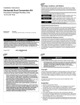
Figure 1. Roof mounted unit
Outdoor Unit
Gas (Suction)
Line - Insulated
Liquid Line
Insulated
Unit Mounting
Channels
Elevation
(Mounting Frame)
Roof Trussing
Ceiling
Roof
Construction
6”
Radius
Ground Level Mounting
For ground level installation, the unit base should be
adequately supported and hold the unit near level. The
installation must meet the guidelines set forth in local
codes. The support should extend two inches beyond
the unit base channels at all points. The unit and
support must be isolated from any adjacent structure
to prevent possible noise or vibration problems. Any
ground level location must comply with required
clearances given in the unit dimensional drawings (see
“Dimensional Data,” p. 10).
Installation Checklist
Complete this checklist once the unit is installed to
verify that all recommended procedures have been
accomplished before starting the system. Do not
operate the system until all items covered by this
checklist are complete.
☐ Inspect unit location for proper required service
clearances.
☐ Inspect unit location for proper free air clearances.
☐ Inspect unit location for secure, level mounting
position.
Refrigerant Piping
☐ Properly sized/constructed liquid and suction lines
connected to stubs at both the indoor and outdoor
units?
☐ Insulated the entire suction line?
☐ Insulated portions of liquid line exposed to
extremes in temperature?
☐ Performed initial leak test?
PPrree--IInnssttaallllaattiioonn

SS-SVX12G-EN
9
☐ Evacuated each refrigerant circuit to 500 microns?
☐ Charged each circuit with proper amount of R-22?
Electrical Wiring
☐ Provided unit power wiring (with disconnect) to
proper terminals in the unit control section?
☐ Installed system indoor thermostat?
☐ Installed system low voltage interconnecting wiring
to proper terminals of outdoor unit, indoor unit and
system thermostat?
PPrree--IInnssttaallllaattiioonn

10
SS-SVX12G-EN
Dimensional Data
Figure 2. Height, width and depth measurements
H
W
D
H
W
D
H - in. (mm) W - in. (mm) D - in. (mm)
TTA0902*A
46.1 (1171) 45 (1143) 38 (965.2)
TTA1202*A
46.1 (1171) 55 (1397) 42 (1067)
TTA1802*D, 2402*D 52.1 (1323) 96 (2438) 48 (1219)
NNoottee:: Full dimensional data available on next pages.

SS-SVX12G-EN
11
Figure 3. 7.5 ton condensing unit, single compressor, microchannel
BOTTOM
OF UNIT
14 3/8"
(365.1)
26 15/16"
(684.2)
39 3/16"
(995.3)
2 7/8"
(73)
1 7/8"
(47.6)
33 13/16"
(858.8)
1/16"
(1.59)
6" (152.4)
21 11/16"
(550.9)
6" (152.4)
34 3/4"
(882.6)
40 3/4"
(1035)
3" (76.2)
1 13/16"
(46)
27 11/16"
(703.3)
2 5/16"
(58.7)
4 3/16"
(106.36)
33 7/8"
(860.4)
35 15/16"
(912.8)
40 15/16"
(1039.8)
41 15/16"
(1065.2)
NOTES:
1. ACCESS OPENING IS FOR FIELD INSTALLED BAYLOAM ACCESSORY.
2. MINIMUM CLEARANCE FOR PROPER OPERATION IS 36" (914.4) FROM
WALLS, SHRUBBERY, PRIVACY FENCES ETC. MINIMUM CLEARANCE
BETWEEN ADJACENT UNITS IS 72" (1828.8). RECOMMENDED SERVICE
CLEARANCE 48"
(1219.2)
3. TOP DISCHARGE AREA SHOULD BE UNRESTRICTED FOR 100" (2540)
MINIMUM. UNIT SHOULD BE PLACED SO ROOF RUN-OFF WATER DOES
NOT POUR DIRECTLY ON UNIT
4. OUTDOOR AIR TEMPERATURE SENSOR OPENING (DO NOT BLOCK OPENING)
SERVICE CLEARANCE
48" (1219.2) (SEE NOTE 2
FOR CLEARANCE)
SEE NOTE 1
REFRIGERANT ACCESS
HAIL GUARD
(OPTIONAL)
SERVICE PANEL
SERVICE PANEL
7/16" (11.11) DIA. ISOLATOR MOUNTING
HOLES (OUTSIDE HOLES - 4 PLACES)
SEE NOTE 3
SERVICE PANEL SIDE
SEE NOTE 4
WITH HAIL GUARD
WITH HAIL GUARD
DDiimmeennssiioonnaall DDaattaa

12
SS-SVX12G-EN
Figure 4. 10 ton condensing unit, single compressor, microchannel
BOTTOM
OF UNIT
14 5/16"
(363.5)
26 7/8"
(682.6)
39 1/8"
(993.8)
2 7/8" (73)
1 7/8"
(47.6)
34 1/16" (865.2)
4 1/4"
(108)
1 1/4"
(31.7)
37 11/16"
(957.3)
1/16"
(1.6)
6"
(152.4)
25 11/16"
(652.5)
37 15/16"
(963.6)
3" (76.2)
50 3/4"
(1289)
44 3/4"
(1136.6)
1 11/16"
(42.9)
31 11/16"
(804.9)
3 13/16"
(96.8)
2 3/16"
(55.6)
39 15/16"
(1014.4)
50 15/16"
(1294)
51 15/16"
(1319.2)
SERVICE PANEL SIDE
SERVICE CLEARANCE
48" (1219.2) (SEE NOTE 2
FOR CLEARANCE
HAIL GUARD
(OPTIONAL)
SERVICE PANEL
SEE NOTE 3
HAIL GUARD
(OPTIONAL)
SERVICE PANEL
CONTROL WIRING
LINE VOLTAGE
REFRIGERANT ACCESS
SEE NOTE 1
SEE NOTE 4
WITH HAIL GUARD
7/16" (11.1) DIA. ISOLATOR MOUNTING
HOLES (OUTSIDE HOLES - 4 PLACES)
NOTES:
1. ACCESS OPENING IS FOR FIELD INSTALLED BAYLOAM ACCESSORY.
2. MINIMUM CLEARANCE FOR PROPER OPERATION IS 36" (914.4) FROM
WALLS, SHRUBBERY, PRIVACY FENCES ETC. MINIMUM CLEARANCE
BETWEEN ADJACENT UNITS IS 72" (1828.8). RECOMMENDED SERVICE
CLEARANCE 48" (1219.2)
3. TOP DISCHARGE AREA SHOULD BE UNRESTRICTED FOR 100" (2540)
MINIMUM. UNIT SHOULD BE PLACED SO ROOF RUN-OFF WATER DOES
NOT POUR DIRECTLY ON UNIT
4. OUTDOOR AIR TEMPERATURE SENSOR OPENING (DO NOT BLOCK OPENING)
WITH HAIL GUARD
6"
(152.4)
DDiimmeennssiioonnaall DDaattaa

SS-SVX12G-EN
13
Figure 5. 15–20 ton condensing unit, dual compressor, microchannel
20 1/16”
(509.6)
DDiimmeennssiioonnaall DDaattaa

14
SS-SVX12G-EN
Weights
Cooling Condenser
Table 1. TTA unit and corner weights — lbs (60 Hz)
Tons Model No.
Shipping
Max (lbs)
Net Max
(lbs)
Corner Weights
1 2 3 4
7.5 TTA0902*A 328 280 73 89 51 67
10 TTA1202*A 405 329 107 84 60 77
15 TTA1802*D 776 661 141 228 112 180
20 TTA2402*D 922 756 180 265 122 190
Figure 6. TTA0902*A, 1202*A
#1
#2
#3
#4
LIFTING HOLES
(BOTH SIDES)
SERVICE
ACCESS
Figure 7. TTA1802*D, 2402*D
SERVICE
ACCESS
SERVICE
A
C
CE
SS
#1
#2
#3
#4
LIFTING HOLES
(BOTH SIDES)

SS-SVX12G-EN
15
Installation
Refrigerant Piping Guidelines
Figure 8. Allowable elevation difference: TTA above indoor unit
Contact manufacturer for review
Figure 9. Allowable elevation difference: TTA or TWA below indoor unit
Acceptable liquid-riser height
based on total liquid-line length
(below indoor unit)
Contact manufacturer for review
NNoottee:: Route refrigerant piping for minimum linear length, minimum number of bends and fittings.

16
SS-SVX12G-EN
Refrigerant Piping Procedures
(Outdoor Units)
WWAARRNNIINNGG
RReeffrriiggeerraanntt uunnddeerr HHiigghh PPrreessssuurree!!
FFaaiilluurree ttoo ffoollllooww iinnssttrruuccttiioonnss bbeellooww ccoouulldd rreessuulltt iinn
aann eexxpplloossiioonn wwhhiicchh ccoouulldd rreessuulltt iinn ddeeaatthh oorr
sseerriioouuss iinnjjuurryy oorr eeqquuiippmmeenntt ddaammaaggee..
SSyysstteemm ccoonnttaaiinnss rreeffrriiggeerraanntt uunnddeerr hhiigghh pprreessssuurree..
RReeccoovveerr rreeffrriiggeerraanntt ttoo rreelliieevvee pprreessssuurree bbeeffoorree
ooppeenniinngg tthhee ssyysstteemm.. SSeeee uunniitt nnaammeeppllaattee ffoorr
rreeffrriiggeerraanntt ttyyppee.. DDoo nnoott uussee nnoonn--aapppprroovveedd
rreeffrriiggeerraannttss,, rreeffrriiggeerraanntt ssuubbssttiittuutteess,, oorr rreeffrriiggeerraanntt
aaddddiittiivveess..
WWAARRNNIINNGG
EExxpplloossiioonn HHaazzaarrdd!!
FFaaiilluurree ttoo ffoollllooww iinnssttrruuccttiioonnss bbeellooww ccoouulldd rreessuulltt iinn
aann eexxpplloossiioonn wwhhiicchh ccoouulldd rreessuulltt iinn ddeeaatthh oorr
sseerriioouuss iinnjjuurryy,, aanndd eeqquuiippmmeenntt ddaammaaggee..
NNEEVVEERR bbyyppaassss ssyysstteemm ssaaffeettiieess iinn oorrddeerr ttoo ppuummpp
ddoowwnn tthhee uunniitt ccoommppoonneenntt''ss rreeffrriiggeerraanntt iinnttoo tthhee
mmiiccrroocchhaannnneell hheeaatt eexxcchhaannggeerr ((MMCCHHEE)) ccooiill.. DDoo
NNOOTT ddeepprreessss tthhee ccoommpprreessssoorr ccoonnttaaccttoorr ssiinnccee iitt
eeffffeeccttiivveellyy bbyyppaasssseess tthhee hhiigghh--pprreessssuurree ccoonnttrrooll..
Each unit ships with a holding charge of dry nitrogen.
The nitrogen should be removed and the entire system
evacuated (at the proper time) to avoid possible
contamination.
1. Remove the compressor service access panel.
2. Locate the liquid and suction line access valves.
Check that the piping connection stubs (Figure 10,
p. 16) line up properly with the holes in the unit
cabinet.
Figure 10. Outdoor units - refrigerant piping (with dry
nitrogen)
Gas Line Gauge Port
Manifold
Gauges
Liquid Line Gauge Port
3. Install gauges to determine if the circuits are still
pressurized. If not, the charge has escaped and
should be repaired as required to obtain a leak-free
circuit. If the circuits are still pressurized, use the
gauges to slowly release the nitrogen charge to the
atmosphere and remove both seal caps from the
outdoor unit connection stubs.
NNOOTTIICCEE
SSyysstteemm CCoommppoonneenntt DDaammaaggee!!
DDoo nnoott rreemmoovvee tthhee sseeaall ccaappss ffrroomm rreeffrriiggeerraanntt
ccoonnnneeccttiioonnss uunnttiill pprreeppaarreedd ttoo bbrraazzee rreeffrriiggeerraanntt
lliinneess ttoo tthhee ccoonnnneeccttiioonnss.. EExxcceessssiivvee eexxppoossuurree ttoo
aattmmoosspphheerree ((>> 55 mmiinn..)) mmaayy aallllooww mmooiissttuurree oorr ddiirrtt
ttoo ccoonnttaammiinnaattee tthhee ssyysstteemm,, ddaammaaggiinngg vvaallvvee sseeaallss
aanndd ccaauussiinngg iiccee ffoorrmmaattiioonn iinn ssyysstteemm ccoommppoonneennttss..
IInnssttaallllaattiioonn

SS-SVX12G-EN
17
WWAARRNNIINNGG
EExxpplloossiioonn HHaazzaarrdd aanndd DDeeaaddllyy GGaasseess!!
FFaaiilluurree ttoo ffoollllooww aallll pprrooppeerr ssaaffee rreeffrriiggeerraanntt
hhaannddlliinngg pprraaccttiicceess ccoouulldd rreessuulltt iinn ddeeaatthh oorr sseerriioouuss
iinnjjuurryy..
NNeevveerr ssoollddeerr,, bbrraazzee oorr wweelldd oonn rreeffrriiggeerraanntt lliinneess oorr
aannyy uunniitt ccoommppoonneennttss tthhaatt aarree aabboovvee aattmmoosspphheerriicc
pprreessssuurree oorr wwhheerree rreeffrriiggeerraanntt mmaayy bbee pprreesseenntt..
AAllwwaayyss rreemmoovvee rreeffrriiggeerraanntt bbyy ffoolllloowwiinngg tthhee
gguuiiddeelliinneess eessttaabblliisshheedd bbyy tthhee EEPPAA FFeeddeerraall CClleeaann
AAiirr AAcctt oorr ootthheerr ssttaattee oorr llooccaall ccooddeess aass aapppprroopprriiaattee..
AAfftteerr rreeffrriiggeerraanntt rreemmoovvaall,, uussee ddrryy nniittrrooggeenn ttoo
bbrriinngg ssyysstteemm bbaacckk ttoo aattmmoosspphheerriicc pprreessssuurree bbeeffoorree
ooppeenniinngg ssyysstteemm ffoorr rreeppaaiirrss.. MMiixxttuurreess ooff
rreeffrriiggeerraannttss aanndd aaiirr uunnddeerr pprreessssuurree mmaayy bbeeccoommee
ccoommbbuussttiibbllee iinn tthhee pprreesseennccee ooff aann iiggnniittiioonn ssoouurrccee
lleeaaddiinngg ttoo aann eexxpplloossiioonn.. EExxcceessssiivvee hheeaatt ffrroomm
ssoollddeerriinngg,, bbrraazziinngg oorr wweellddiinngg wwiitthh rreeffrriiggeerraanntt
vvaappoorrss pprreesseenntt ccaann ffoorrmm hhiigghhllyy ttooxxiicc ggaasseess aanndd
eexxttrreemmeellyy ccoorrrroossiivvee aacciiddss..
4. Cut, fit and braze tubing, starting at the outdoor unit
and work toward the indoor unit.
NNoottee:: Use long radius ells for all 90° bends.
All brazing should be done using a 2 to 3 psig dry
nitrogen purge flowing through the pipe being
brazed, see Figure 10, p. 16.
NNOOTTIICCEE
SSyysstteemm CCoommppoonneenntt DDaammaaggee!!
IInnssttaallll aa rreegguullaattiinngg vvaallvvee bbeettwweeeenn tthhee nniittrrooggeenn
ssoouurrccee aanndd tthhee ggaauuggee mmaanniiffoolldd.. UUnnrreegguullaatteedd
pprreessssuurree ccaann ddaammaaggee ssyysstteemm ccoommppoonneennttss..
NNOOTTIICCEE
SSyysstteemm CCoommppoonneenntt DDaammaaggee!!
WWeett--wwrraapp aallll vvaallvveess aanndd pprrootteecctt ppaaiinntteedd ssuurrffaacceess
ffrroomm eexxcceessssiivvee hheeaatt.. HHeeaatt ccaann ddaammaaggee ssyysstteemm
ccoommppoonneennttss aanndd tthhee uunniitt ffiinniisshh..
5. Shut off nitrogen supply. Shut off the manifold
valve for the line that is connected to the suction
line access valve. Disconnect the line from the
access valve.
Refrigerant Piping Procedures
(Indoor Unit)
Once liquid and suction lines are complete to the
refrigerant connections on the indoor unit, remove the
gauge port core(s) on the indoor unit connection stubs
to release the dry nitrogen charge.
NNOOTTIICCEE
UUnniitt DDaammaaggee!!
DDoo nnoott aappppllyy hheeaatt ttoo rreemmoovvee sseeaall ccaappss uunnttiill tthhee
ggaauuggee ppoorrtt ccoorreess hhaavvee bbeeeenn rreemmoovveedd.. IIff sseeaall ccaappss
aarree iinnttaacctt,, aapppplliiccaattiioonn ooff hheeaatt mmaayy ggeenneerraattee
eexxcceessssiivvee pprreessssuurree iinn tthhee uunniitt aanndd rreessuulltt iinn
ddaammaaggee ttoo tthhee ccooiill oorr eexxppaannssiioonn vvaallvvee..
1. Remove both seal caps from the indoor unit
connection stubs.
NNOOTTIICCEE
UUnniitt DDaammaaggee!!
DDoo nnoott rreemmoovvee tthhee sseeaall ccaappss ffrroomm rreeffrriiggeerraanntt
ccoonnnneeccttiioonnss uunnttiill pprreeppaarreedd ttoo bbrraazzee rreeffrriiggeerraanntt
lliinneess ttoo tthhee ccoonnnneeccttiioonnss..
2. Turn on nitrogen supply. Nitrogen enters through
the liquid line gauge port.
3. Braze the liquid line connections.
4. Open the gauge port on the suction line and then
braze the suction line to the connection stub.
Nitrogen will bleed out the open gauge port on the
suction line.
5. Shut off nitrogen supply.
Leak Check
WWAARRNNIINNGG
EExxpplloossiioonn HHaazzaarrdd!!
FFaaiilluurree ttoo ffoollllooww tthheessee iinnssttrruuccttiioonnss ccoouulldd rreessuulltt iinn
ddeeaatthh oorr sseerriioouuss iinnjjuurryy oorr eeqquuiippmmeenntt oorr pprrooppeerrttyy--
oonnllyy ddaammaaggee..
UUssee oonnllyy ddrryy nniittrrooggeenn wwiitthh aa pprreessssuurree rreegguullaattoorr ffoorr
pprreessssuurriizziinngg uunniitt.. DDoo nnoott uussee aacceettyylleennee,, ooxxyyggeenn oorr
ccoommpprreesssseedd aaiirr oorr mmiixxttuurreess ccoonnttaaiinniinngg tthheemm ffoorr
pprreessssuurree tteessttiinngg.. DDoo nnoott uussee mmiixxttuurreess ooff aa
hhyyddrrooggeenn ccoonnttaaiinniinngg rreeffrriiggeerraanntt aanndd aaiirr aabboovvee
aattmmoosspphheerriicc pprreessssuurree ffoorr pprreessssuurree tteessttiinngg aass tthheeyy
mmaayy bbeeccoommee ffllaammmmaabbllee aanndd ccoouulldd rreessuulltt iinn aann
eexxpplloossiioonn.. RReeffrriiggeerraanntt,, wwhheenn uusseedd aass aa ttrraaccee ggaass
sshhoouulldd oonnllyy bbee mmiixxeedd wwiitthh ddrryy nniittrrooggeenn ffoorr
pprreessssuurriizziinngg uunniittss..
WWAARRNNIINNGG
EExxpplloossiioonn HHaazzaarrdd!!
FFaaiilluurree ttoo ffoollllooww ssaaffee lleeaakk tteesstt pprroocceedduurreess bbeellooww
ccoouulldd rreessuulltt iinn ddeeaatthh oorr sseerriioouuss iinnjjuurryy oorr
eeqquuiippmmeenntt oorr pprrooppeerrttyy--oonnllyy--ddaammaaggee..
NNeevveerr uussee aann ooppeenn ffllaammee ttoo ddeetteecctt ggaass lleeaakkss.. UUssee aa
lleeaakk tteesstt ssoolluuttiioonn ffoorr lleeaakk tteessttiinngg..
After the brazing operation of refrigerant lines to both
the outdoor and indoor unit is completed, the field
brazed connections must be checked for leaks.
Pressurize the system through the access valve with
IInnssttaallllaattiioonn

18
SS-SVX12G-EN
dry nitrogen to 200 psi. Use soap bubbles or other leak-
checking methods to ensure that all field joints are leak
free. If not, release pressure, repair and repeat leak test.
System Evacuation
1. After completion of leak check, evacuate the
system.
2. Attach appropriate hoses from manifold gauge to
gas and liquid line pressure taps.
NNoottee:: Unnecessary switching of hoses can be
avoided and complete evacuation of all lines
leading to sealed system can be
accomplished with manifold center hose and
connecting branch hose to a cylinder of R–22
and vacuum pump.
3. Attach center hose of manifold gauges to vacuum
pump.
NNOOTTIICCEE
OOppeerraattiinngg UUnnddeerr VVaaccuuuumm!!
FFaaiilluurree ttoo ffoollllooww tthheessee iinnssttrruuccttiioonnss wwiillll rreessuulltt iinn
ccoommpprreessssoorr ffaaiilluurree..
DDoo nnoott ooppeerraattee oorr aappppllyy ppoowweerr ttoo tthhee ccoommpprreessssoorr
wwhhiillee uunnddeerr aa vvaaccuuuumm..
4. Evacuate the system to hold a 500 micron vacuum.
5. Close off valve to vacuum pump and observe the
micron gauge. If gauge pressure rises above 500
microns in one minute, then evacuation is
incomplete or the system has a leak.
6. If vacuum gauge does not rise above 500 microns in
10 minutes, the evacuation should be complete.
NNOOTTIICCEE
EEqquuiippmmeenntt DDaammaaggee!!
CChhaarrggee wwiitthh aacccceessss ppoorrtt oonn tthhee lliiqquuiidd lliinnee oonnllyy..
7. With vacuum pump and micron gauge blanked off,
open valve on R–22 cylinder and allow refrigerant
pressure to build up to about 80 psig.
8. Close valve on the R–22 supply cylinder. Close
valves on manifold gauge set and remove
refrigerant charging hoses from liquid and gas
gauge ports.
9. Leak test the entire system. Using proper
procedures and caution, as described in the
previous section, repair any leaks found and repeat
the leak test.
Insulating and Isolating
Refrigerant Lines
Insulate the entire suction line with refrigerant piping
insulation. Also insulate any portion of the liquid line
exposed to temperature extremes. Insulate and isolate
liquid and suction lines from each other. Isolate
refrigerant lines from the structure and any duct work.
IImmppoorrttaanntt::
1. To prevent possible noise or vibration
problems, be certain to isolate
refrigerant lines from the building.
2. All suction and hot gas bypass piping (if
installed) should be insulated from the
termination in the air handler to the
condensing unit cabinet entry. Failure
to do so can cause condensate drip off
and performance degradation.
3. Prior to starting a unit, it is advisable to
have the approved oils available in the
event oil needs to be added to the
system.
NNOOTTIICCEE
EEqquuiippmmeenntt DDaammaaggee!!
TThhiiss iiss PPOOEE ooiill,, wwhhiicchh rreeaaddiillyy aabbssoorrbbss mmooiissttuurree..
AAllwwaayyss uussee nneeww ooiill aanndd nneevveerr lleeaavvee ccoonnttaaiinneerrss
ooppeenn ttoo aattmmoosspphheerree wwhhiillee nnoott iinn uussee..
Table 2. R-22 TTA approved oils
Unit Model Number
Approved Oils
TTA0902*A, TTA1202*A,
TTA1802*B, TTA2402*B
Trane Oil Part Number
OIL00094
(1 quart container)
For units equipped with compressors containing site
glasses, the oil level must be visible through the sight
glass when the compressor is running under stabilized
conditions and a few minutes after the compressor has
stopped.
Refrigerant Charging Procedure
If charging by weight, refer to for starting change. If
refrigerant adjustments are needed because of length
of line, refer to the Charging Charts and Superheat
values in the unit’s Service Facts.
Charge by weight through the gauge port on the liquid
line.
IInnssttaallllaattiioonn

SS-SVX12G-EN
19
NNootteess::
• R-22 should only be charged in the liquid
state.
• When possible, always charge the
refrigerant into the liquid line of the unit.
• If the entire charge can’t be charged into the
liquid line, the balance of the unit charge
can be metered through a charging
manifold set as liquid — preferably through
a schrader valve into the suction line to the
compressor — only while the compressor is
running.
• Check and adjust superheat using the
superheat table in the unit’s Service Facts,
then re-check charging charts to determine
if charge corrections are necessary.
NNOOTTIICCEE
EEqquuiippmmeenntt DDaammaaggee!!
NNeevveerr cchhaarrggee lliiqquuiidd rreeffrriiggeerraanntt iinnttoo tthhee ssuuccttiioonn
lliinnee ooff tthhee uunniitt wwiitthh tthhee ccoommpprreessssoorr ooffff..
Figure 11. Outdoor units - refrigerant piping
Gas Line Gauge Port
Liquid Line Gauge Port
Manfold
Guages
Charging Levels
Liquid Charging
This procedure is accomplished with the unit
operating. Electrical connections must be complete. Do
not proceed until the system is ready to operate.
NNoottee:: The compressor access panel must be installed
when the unit is running and being charged.
Manifold hoses must be routed through
refrigerant gauge access hole(s). See
“Dimensional Data,” p. 10 for specific locations.
WWAARRNNIINNGG
LLiivvee EElleeccttrriiccaall CCoommppoonneennttss!!
FFaaiilluurree ttoo ffoollllooww aallll eelleeccttrriiccaall ssaaffeettyy pprreeccaauuttiioonnss
wwhheenn eexxppoosseedd ttoo lliivvee eelleeccttrriiccaall ccoommppoonneennttss ccoouulldd
rreessuulltt iinn ddeeaatthh oorr sseerriioouuss iinnjjuurryy..
WWhheenn iitt iiss nneecceessssaarryy ttoo wwoorrkk wwiitthh lliivvee eelleeccttrriiccaall
ccoommppoonneennttss,, hhaavvee aa qquuaalliiffiieedd lliicceennsseedd eelleeccttrriicciiaann
oorr ootthheerr iinnddiivviidduuaall wwhhoo hhaass bbeeeenn pprrooppeerrllyy ttrraaiinneedd
iinn hhaannddlliinngg lliivvee eelleeccttrriiccaall ccoommppoonneennttss ppeerrffoorrmm
tthheessee ttaasskkss..
1. Turn on power to the unit. Allow the system to run
for 15 minutes to stabilize operating conditions.
2. Measure airflow across the indoor coil. Compare
the measurements with the fan performance data in
the Data/Submittal or Service Facts. Once proper
airflow is established, compare discharge pressure
and liquid temperature to the charging charts. Add
or remove refrigerant (liquid only) as required to
obtain correct discharge pressure and liquid
temperature.
3. Check suction line superheat and condenser sub-
cooling to ensure the unit is operating properly.
4. Disconnect all power to the unit.
IImmppoorrttaanntt:: If the unit is charged and left without
power until a later date, the crankcase
heater should be energized for a
minimum of 8 hours prior to powering
the compressor(s).
WWAARRNNIINNGG
HHaazzaarrddoouuss VVoollttaaggee ww//CCaappaacciittoorrss!!
FFaaiilluurree ttoo ddiissccoonnnneecctt ppoowweerr aanndd ddiisscchhaarrggee
ccaappaacciittoorrss bbeeffoorree sseerrvviicciinngg ccoouulldd rreessuulltt iinn ddeeaatthh oorr
sseerriioouuss iinnjjuurryy..
DDiissccoonnnneecctt aallll eelleeccttrriicc ppoowweerr,, iinncclluuddiinngg rreemmoottee
ddiissccoonnnneeccttss aanndd ddiisscchhaarrggee aallll mmoottoorr ssttaarrtt//rruunn
ccaappaacciittoorrss bbeeffoorree sseerrvviicciinngg.. FFoollllooww pprrooppeerr
lloocckkoouutt//ttaaggoouutt pprroocceedduurreess ttoo eennssuurree tthhee ppoowweerr
ccaannnnoott bbee iinnaaddvveerrtteennttllyy eenneerrggiizzeedd.. FFoorr vvaarriiaabbllee
ffrreeqquueennccyy ddrriivveess oorr ootthheerr eenneerrggyy ssttoorriinngg
ccoommppoonneennttss pprroovviiddeedd bbyy TTrraannee oorr ootthheerrss,, rreeffeerr ttoo
tthhee aapppprroopprriiaattee mmaannuuffaaccttuurreerr’’ss lliitteerraattuurree ffoorr
aalllloowwaabbllee wwaaiittiinngg ppeerriiooddss ffoorr ddiisscchhaarrggee ooff
ccaappaacciittoorrss.. VVeerriiffyy wwiitthh aa CCAATT IIIIII oorr IIVV vvoollttmmeetteerr
rraatteedd ppeerr NNFFPPAA 7700EE tthhaatt aallll ccaappaacciittoorrss hhaavvee
ddiisscchhaarrggeedd..
FFoorr aaddddiittiioonnaall iinnffoorrmmaattiioonn rreeggaarrddiinngg tthhee ssaaffee
ddiisscchhaarrggee ooff ccaappaacciittoorrss,, sseeee PPRROODD--SSVVBB0066**--EENN..
5. Remove the charging system from the unit.
IInnssttaallllaattiioonn

20
SS-SVX12G-EN
6. Replace all panels.
Electrical Wiring
WWAARRNNIINNGG
PPrrooppeerr FFiieelldd WWiirriinngg aanndd GGrroouunnddiinngg
RReeqquuiirreedd!!
FFaaiilluurree ttoo ffoollllooww ccooddee ccoouulldd rreessuulltt iinn ddeeaatthh oorr
sseerriioouuss iinnjjuurryy..
AAllll ffiieelldd wwiirriinngg MMUUSSTT bbee ppeerrffoorrmmeedd bbyy qquuaalliiffiieedd
ppeerrssoonnnneell.. IImmpprrooppeerrllyy iinnssttaalllleedd aanndd ggrroouunnddeedd
ffiieelldd wwiirriinngg ppoosseess FFIIRREE aanndd EELLEECCTTRROOCCUUTTIIOONN
hhaazzaarrddss.. TToo aavvooiidd tthheessee hhaazzaarrddss,, yyoouu MMUUSSTT ffoollllooww
rreeqquuiirreemmeennttss ffoorr ffiieelldd wwiirriinngg iinnssttaallllaattiioonn aanndd
ggrroouunnddiinngg aass ddeessccrriibbeedd iinn NNEECC aanndd yyoouurr llooccaall//
ssttaattee//nnaattiioonnaall eelleeccttrriiccaall ccooddeess..
Field wiring consists of providing power supply to the
unit, installing the system indoor thermostat and
providing low voltage system interconnecting wiring.
Access to electrical connection locations is shown in
“Dimensional Data,” p. 10. Determine proper wire
sizes and unit protective fusing requirements by
referring to the unit nameplate and/or the unit Service
Facts. Field wiring diagrams for accessories are
shipped with the accessory.
Unit Power Supply
The installer must provide line voltage circuit(s) to the
unit main power terminals as shown by the unit wiring
diagrams (available through e-Library or by contacting
a local sales office) or field wiring. Power supply must
include a disconnect switch in a location convenient to
the unit. Ground the unit according to local codes and
provide flexible conduit if codes require and/or if
vibration transmission may cause noise problems.
IImmppoorrttaanntt:: All wiring must comply with applicable
local and national (NEC) codes. Type and
location of disconnect switches must
comply with all applicable codes.
WWAARRNNIINNGG
PPrrooppeerr FFiieelldd WWiirriinngg aanndd GGrroouunnddiinngg
RReeqquuiirreedd!!
FFaaiilluurree ttoo ffoollllooww ccooddee ccoouulldd rreessuulltt iinn ddeeaatthh oorr
sseerriioouuss iinnjjuurryy..
AAllll ffiieelldd wwiirriinngg MMUUSSTT bbee ppeerrffoorrmmeedd bbyy qquuaalliiffiieedd
ppeerrssoonnnneell.. IImmpprrooppeerrllyy iinnssttaalllleedd aanndd ggrroouunnddeedd
ffiieelldd wwiirriinngg ppoosseess FFIIRREE aanndd EELLEECCTTRROOCCUUTTIIOONN
hhaazzaarrddss.. TToo aavvooiidd tthheessee hhaazzaarrddss,, yyoouu MMUUSSTT ffoollllooww
rreeqquuiirreemmeennttss ffoorr ffiieelldd wwiirriinngg iinnssttaallllaattiioonn aanndd
ggrroouunnddiinngg aass ddeessccrriibbeedd iinn NNEECC aanndd yyoouurr llooccaall//
ssttaattee//nnaattiioonnaall eelleeccttrriiccaall ccooddeess..
NNOOTTIICCEE
UUssee CCooppppeerr CCoonndduuccttoorrss OOnnllyy!!
FFaaiilluurree ttoo uussee ccooppppeerr ccoonndduuccttoorrss ccoouulldd rreessuulltt iinn
eeqquuiippmmeenntt ddaammaaggee aass tthhee eeqquuiippmmeenntt wwaass nnoott
ddeessiiggnneedd oorr qquuaalliiffiieedd ttoo aacccceepptt ootthheerr ttyyppeess ooff
ccoonndduuccttoorrss..
Low Voltage Wiring
Mount the indoor thermostat, zone sensor, or Night
Setback Panel (NSB) in accordance with the
corresponding thermostat installation instructions.
Install color-coded, weather-proof, multi-wire cable
according to the field wiring schematics (see “Field
Wiring,” p. 21).
Electromechanical Controls
Wiring shown with dashed lines is to be furnished and
installed by the customer. All customer supplied wiring
must be copper only and must conform to NEC and
local electrical codes. Codes may require line of sight
between disconnect switch and unit.
NNoottee:: When electric heater accessory is used, single
point power entry or dual point power entry is
field optional. Single point power entry option is
through electric heater only.
IImmppoorrttaanntt:: For the EDC switch to be functional and
thereby facilitate reliable unit operation,
make the EDC connections from the indoor
to the outdoor control boxes.
Figure 12. Electromechanical jobsite connections
T’stat
Air Handler
Disconnect Switch
(By Others)
Disconnect Switch
(By Others) Note 2
Electric
Heat Accessory
Disconnect Switch
(By Others)
B
A
B
D
C
A.
3 power wires, line voltage for 3 phase, (2 power wires for
single phase)
B.
3 power wires, line voltage for 3 phase, (2 power wires for
single phase)
C.
Cooling only thermostat: 3 to 7 wires depending on stages of
electric heat
D.
3 to 7 wires depending on type of outdoor unit(s)
IInnssttaallllaattiioonn
/