
IMPORTANT: IMPORTANT : IMPORTANTE:
Read Before Using Lire avant usage Leer antes de usar
For English Version Version française Versión en español
See page 2 Voir page 16 Ver la página 30
Operating/Safety Instructions
Consignes de fonctionnement/sécurité
Instrucciones de funcionamiento y seguridad
1-877-BOSCH99 (1-877-267-2499) www.boschtools.com
Call Toll Free for
Consumer Information
& Service Locations
Pour obtenir des informations
et les adresses de nos centres
de service après-vente,
appelez ce numéro gratuit
Llame gratis para
obtener información
para el consumidor y
ubicaciones de servicio
CCS180
2610046822.qxp_CCS180 3/23/17 1:20 PM Page 1

-2-
Work area safety
Keep work area clean and well lit. Cluttered
or dark areas invite accidents.
Do not operate power tools in explosive
atmospheres, such as in the presence of
flammable liquids, gases or dust. Power
tools create sparks which may ignite the dust
or fumes.
Keep children and bystanders away while
operating a power tool. Distractions can
cause you to lose control.
Electrical safety
Power tool plugs must match the outlet.
Never modify the plug in any way. Do not
use any adapter plugs with earthed
(grounded) power tools. Unmodified plugs
and matching outlets will reduce risk of electric
shock.
Avoid body contact with earthed or grounded
surfaces such as pipes, radiators, ranges
and refrigerators. There is an increased risk
of electric shock if your body is earthed or
grounded.
Do not expose power tools to rain or wet
conditions. Water entering a power tool will
increase the risk of electric shock.
Do not abuse the cord. Never use the cord
for carrying, pulling or unplugging the power
tool. Keep cord away from heat, oil, sharp
edges or moving parts. Damaged or entangled
cords increase the risk of electric shock.
When operating a power tool outdoors,
use an extension cord suitable for outdoor
use. Use of a cord suitable for outdoor use
reduces the risk of electric shock.
If operating a power tool in a damp location
is unavoidable, use a Ground Fault Circuit
Interrupter (GFCI) protected supply. Use of
an GFCI reduces the risk of electric shock.
Personal safety
Stay alert, watch what you are doing and
use common sense when operating a
power tool. Do not use a power tool while
you are tired or under the influence of drugs,
alcohol or medication. A moment of inattention
while operating power tools may result in
serious personal injury.
Use personal protective equipment. Always
Read all safety warnings and all instructions. Failure to follow the
warnings and instructions may result in electric shock, fire and/or serious
injury.
SAVE ALL WARNINGS AND INSTRUCTIONS FOR FUTURE REFERENCE
The term “power tool” in the warnings refers to your mains-operated (corded) power tool or
battery-operated (cordless) power tool.
General Power Tool Safety Warnings
Safety Symbols
The definitions below describe the level of severity for each signal word. Please read the manual
and pay attention to these symbols.
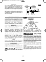
!
This is the safety alert symbol. It is used to alert you to potential
personal injury hazards. Obey all safety messages that follow this
symbol to avoid possible injury or death.
DANGER indicates a hazardous situation which, if not avoided, will
result in death or serious injury.
WARNING indicates a hazardous situation which, if not avoided, could
result in death or serious injury.
CAUTION, used with the safety alert symbol, indicates a hazardous
situation which, if not avoided, will result in minor or moderate injury.
2610046822.qxp_CCS180 3/23/17 1:20 PM Page 2

-3-
w
ear eye protection. Protective equipment
such as dust mask, non-skid safety shoes, hard
hat, or hearing protection used for appropriate
conditions will reduce personal injuries.
Prevent unintentional starting. Ensure the
switch is in the off-position before
connecting to power source and / or battery
pack, picking up or carrying the tool.
Carrying power tools with your finger on the
switch or energizing power tools that have the
switch on invites accidents.
Remove any adjusting key or wrench before
turning the power tool on. A wrench or a
key left attached to a rotating part of the power
tool may result in personal injury.
Do not overreach. Keep proper footing and
balance at all times. This enables better
control of the power tool in unexpected
situations.
Dress properly. Do not wear loose clothing
or jewelry. Keep your hair, clothing and
gloves away from moving parts. Loose
clothes, jewelry or long hair can be caught in
moving parts.
If devices are provided for the connection
of dust extraction and collection facilities,
ensure these are connected and properly
used. Use of dust collection can reduce dust-
related hazards.
Power tool use and care
Do not force the power tool. Use the
correct power tool for your application. The
correct power tool will do the job better and
safer at the rate for which it was designed.
Do not use the power tool if the switch does
not turn it on and off. Any power tool that
cannot be controlled with the switch is
dangerous and must be repaired.
Disconnect the plug from the power source
and/or the battery pack from the power tool
before making any adjustments, changing
accessories, or storing power tools. Such
preventive safety measures reduce the risk of
starting the power tool accidentally.
Store idle power tools out of the reach of
children and do not allow persons unfamiliar
with the power tool or these instructions to
o
perate the power tool. Power tools are
dangerous in the hands of untrained users.
Maintain power tools. Check for misalignment
or binding of moving parts, breakage of
parts and any other condition that may
affect the power tool’s operation. If damaged,
have the power tool repaired before use.
Many accidents are caused by poorly
maintained power tools.
Keep cutting tools sharp and clean. Properly
maintained cutting tools with sharp cutting
edges are less likely to bind and are easier to
control.
Use the power tool, accessories and tool
bits etc. in accordance with these instructions,
taking into account the working conditions
and the work to be performed. Use of the
power tool for operations different from those
intended could result in a hazardous situation.
Battery tool use and care
Recharge only with the charger specified
by the manufacturer. A charger that is
suitable for one type of battery pack may
create a risk of fire when used with another
battery pack.
Use power tools only with specifically
designated battery packs. Use of any other
battery packs may create a risk of injury and
fire.
When battery pack is not in use, keep it
away from other metal objects like paper
clips, coins, keys, nails, screws, or other
small metal objects that can make a
connection from one terminal to another.
Shorting the battery terminals together may
cause burns or a fire.
Under abusive conditions, liquid may be
ejected from the battery, avoid contact. If
contact accidentally occurs, flush with
water. If liquid contacts eyes, additionally
seek medical help. Liquid ejected from the
battery may cause irritation or burns.
Service
Have your power tool serviced by a qualified
repair person using only identical
replacement parts. This will ensure that the
safety of the power tool is maintained.
2610046822.qxp_CCS180 3/23/17 1:20 PM Page 3

Cutting procedures
Keep hands away from
cutting area and the blade.
Keep your second hand on auxiliary handle,
or motor housing. If both hands are holding
the saw, they cannot be cut by the blade.
Do not reach underneath the workpiece.
The guard cannot protect you from the blade
below the workpiece.
Adjust the cutting depth to the thickness of
the workpiece. Less than a full tooth of the
blade teeth should be visible below the
workpiece.
Never hold piece being cut in your hands
or across your leg. Secure the workpiece to
stable platform. It is important to support the
work properly to minimize body exposure,
blade binding, or loss of control.
Hold power tool by insulated gripping
surfaces when performing an operation
where the cutting tool may contact hidden
wiring. Contact with a "live" wire will also make
exposed metal parts of the tool “live” and shock
the operator.
When ripping always use a rip fence or
straight edge guide. This improves the
accuracy of cut and reduces the chance for
blade binding.
Always use blades with correct size and
shape (diamond versus round) of arbor
holes. Blades that do not match the mounting
hardware of the saw will run eccentrically,
causing loss of control.
Never use damaged or incorrect blade
washers or bolt. The blade washers and bolt
were specially designed for your saw, for
optimum performance and safety of operation.
This product is intended to cut wood and
wood-like products only. Dust build up
around the lower guard and hub from other
materials (plastic, masonry or metal) may
disable the lower guard operation.
Inspect the condition and quality of the
wood and remove all nails from lumber
before cutting. Wet lumber, green lumber or
pressure treated lumber require special
attention during cutting operation to prevent
kickback.
Hold the saw firmly to prevent loss of
control. Figures in this manual illustrate
typical hand support of the saw.
Depending upon use, the switch may not
last the life of the saw. If the switch should
fail in the “OFF” position, the saw may not
start. If it should fail while the saw is
running, the saw may not shut off. If either
occurs, unplug the saw immediately and do
not use until repaired.
This circular saw should not be mounted to
a table and converted to a table saw.
Circular saws are not designed or intended to
be used as table saws.
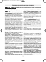
Kickback and related warnings
Causes and operator prevention of
kickback:
Kickback is a sudden reaction to a pinched,
bound or misaligned saw blade, causing an
uncontrolled saw to lift up and out of the
workpiece toward the operator.
When the blade is pinched or bound tightly by
the kerf closing down, the blade stalls and the
motor reaction drives the unit rapidly back
toward the operator.
If the blade becomes twisted or misaligned in
the cut, the teeth at the back edge of the blade
can dig into the top surface of the wood
causing the blade to climb out of the kerf and
jump back toward the operator.
Kickback is the result of tool misuse and/or
incorrect operating procedures or conditions
and can be avoided by taking proper
precautions as given below:
Maintain a firm grip with both hands on the
saw and position your arms to resist
kickback forces. Position your body to
either side of the blade, but not in line with
the blade. Kickback could cause the saw to
jump backwards, but kickback forces can be
controlled by the operator, if proper
precautions are taken.
When blade is binding, or when interrupting
a cut for any reason, release the trigger and
hold the saw motionless in the material
until the blade comes to a complete stop.
Never attempt to remove the saw from the
work or pull the saw backward while the
blade is in motion or kickback may occur.
Investigate and take corrective action to
eliminate the cause of blade binding.
When restarting a saw in a workpiece,
center the saw blade in the kerf and check
that saw teeth are not engaged into the
-4-
Safety Rules for Circular Saws
Read all safety warnings and all instructions.
2610046822.qxp_CCS180 3/23/17 1:20 PM Page 4

-5-
material. If saw blade is binding, it may walk
up or kickback from the workpiece as the saw
is restarted.
Support large panels to minimize the risk of
blade pinching and kickback. Large panels
tend to sag under their own weight. Supports
must be placed under the panel on both sides,
near the line of cut and near the edge of the
panel.
Do not use dull or damaged blades.
Unsharpened or improperly set blades
produce narrow kerf causing excessive friction,
blade binding and kickback.
Blade depth and bevel adjusting locking
levers must be tight and secure before
making cut. If blade adjustment shifts while
cutting, it may cause binding and kickback.
Use extra caution when sawing into
existing walls or other blind areas. The
protruding blade may cut objects that can
cause kickback.
The blade washers and the bolt on your
saw have been designed to work as a
clutch to reduce the intensity of a kickback.
Understand the operation and settings of
the VARI-TORQUE CLUTCH. The proper
setting of the clutch, combined with firm
handling of the saw will allow you to control
kickback.
Never place your hand behind the saw
blade. Kickback could cause the saw to jump
backwards over your hand.
Do not use the saw with an excessive
depth of cut setting. Too much blade
exposure increases the likelihood of the blade
twisting in the kerf and increases the surface
area of the blade available for pinching that
leads to kickback.
Lower guard function
Check lower guard for proper closing
before each use. Do not operate saw if
lower guard does not move freely and
close instantly. Never clamp or tie the lower
guard into the open position. If saw is
accidentally dropped, lower guard may be
bent. Raise the lower guard only with the lower
guard lift lever and make sure it moves freely
and does not touch the blade or any other part,
in all angles and depths of cut.
Check the operation of the lower guard
spring. If the guard and the spring are not
operating properly, they must be serviced
before use. Lower guard may operate
sluggishly due to damaged parts, gummy
deposits, or a buildup of debris.
Lower guard should be retracted manually
only for special cuts such as “Plunge Cuts”
and “Compound Cuts”. Raise lower guard
by lower guard lift lever and as soon as
blade enters the material, lower guard must
be released. For all other sawing, the lower
guard should operate automatically.
Always observe that the lower guard is
covering the blade before placing saw
down on bench or floor. An unprotected,
coasting blade will cause the saw to walk
backwards, cutting whatever is in its path. Be
aware of the time it takes for the blade to stop
after switch is released.
Do not run the tool while carrying it at your
side. Lower guard may be opened by a
contact with your clothing. Accidental
contact with the spinning saw blade could
result in serious personal injury.
Periodically remove the blade, clean the
upper, lower guards and the hub area with
kerosene and wipe it dry, or blow it clean
with compressed air. Preventive maintenance
and properly operating guard will reduce the
probability of an accident.
KICKBACK
KICKBACK
2610046822.qxp_CCS180 3/23/17 1:20 PM Page 5

-6-
Additional Safety Warnings
Use only Bosch batteries recommended in
the charger Operating Instructions included
with your tool. Using other types of batteries
may result in personal injury or property damage.
Ensure the switch is in the off position
before inserting battery pack. Inserting the
battery pack into power tools that have the
switch on invites accidents.
GFCI and personal protection devices like
electrician’s rubber gloves and footwear will
further enhance your personal safety.
Do not use AC only rated tools with a DC
power supply. While the tool may appear to
work, the electrical components of the AC
rated tool are likely to fail and create a hazard
to the operator.
Keep handles dry, clean and free from oil
and grease. Slippery hands cannot safely
control the power tool.
Develop a periodic maintenance schedule
for your tool. When cleaning a tool be
careful not to disassemble any portion of
the tool since internal wires may be
misplaced or pinched or safety guard return
springs may be improperly mounted. Certain
cleaning agents such as gasoline, carbon
tetrachloride, ammonia, etc. may damage
plastic parts.
Some dust created by
power sanding, sawing,
grinding, drilling, and other construction
activities contains chemicals known to
cause cancer, birth defects or other
reproductive harm. Some examples of
these chemicals are:
• Lead from lead-based paints,
• Crystalline silica from bricks and cement and
other masonry products, and
• Arsenic and chromium from chemically-
treated lumber.
Your risk from these exposures varies,
depending on how often you do this type of
work. To reduce your exposure to these
chemicals: work in a well ventilated area, and
work with approved safety equipment, such as
those dust masks that are specially designed
to filter out microscopic particles.
2610046822.qxp_CCS180 3/23/17 1:20 PM Page 6

-7-
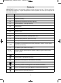
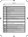
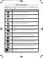
Symbols
IMPORTANT: Some of the following symbols may be used on your tool. Please study them
and learn their meaning. Proper interpretation of these symbols will allow you to operate the
tool better and safer.
Symbol Designation / Explanation
V Volts (voltage)
A Amperes (current)
Ah Amp-hour (measurement of battery capacity)
Hz Hertz (frequency, cycles per second)
W Watt (power)
kg Kilograms (weight)
min Minutes (time)
s Seconds (time)
⌀
Diameter (size of drill bits, grinding wheels, etc.)
n
0
No load speed (rotational speed at no load)
n Rated speed (maximum attainable speed)
.../min
Revolutions or reciprocation per minute (revolutions, strokes, surface speed,
orbits etc. per minute)
0 Off position (zero speed, zero torque...)
1, 2, 3, ...
I, II, III,
Selector settings (speed, torque or position settings. Higher number means
greater speed)
0
Infinitely variable selector with off (speed is increasing from 0 setting)
Arrow (action in the direction of arrow)
Alternating current (type or a characteristic of current)
Direct current (type or a characteristic of current)
Alternating or direct current (type or a characteristic of current)
Class II construction (designates double insulated construction tools)
Earthing terminal (grounding terminal)
2610046822.qxp_CCS180 3/23/17 1:20 PM Page 7

-8-
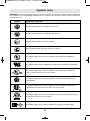
Symbols (continued)
IMPORTANT: Some of the following symbols may be used on your tool. Please study them
and learn their meaning. Proper interpretation of these symbols will allow you to operate the
tool better and safer.
Symbol Designation / Explanation
Designates Li-ion battery recycling program
Designates Ni-Cad battery recycling program
Alerts user to read manual
Alerts user to wear eye protection
This symbol designates that this tool is listed by Underwriters Laboratories.
This symbol designates that this component is recognized by Underwriters
Laboratories.
This symbol designates that this tool is listed by Underwriters Laboratories,
to United States and Canadian Standards.
This symbol designates that this tool is listed by the Canadian Standards
Association.
This symbol designates that this tool is listed by the Canadian Standards
Association, to United States and Canadian Standards.
This symbol designates that this tool is listed by the Intertek Testing
Services, to United States and Canadian Standards.
This symbol designates that this tool complies to NOM Mexican Standards.
2610046822.qxp_CCS180 3/23/17 1:20 PM Page 8

-9-
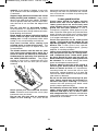
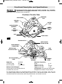
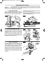
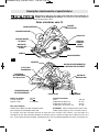
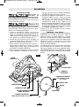
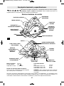
Functional Description and Specifications
FOOT
LOWER
GUARD LIFT
LEVER
AUXILIARY
HANDLE
BEVEL
ADJUSTMENT
KNOB
CALIBRATED BEVEL
QUADRANT
Disconnect battery pack from tool before making any assembly,
adjustments or changing accessories. Such preventive safety measures
reduce the risk of starting the tool accidentally.
Cordless Circular Saw
UPPER GUARD
LOWER GUARD
LOCK
BUTTON
FIG. 1
BATTERY
PACK
SAFETY SWITCH
RELEASE BUTTON
TRIGGER SWITCH
BLADE WRENCH &
STORAGE AREA
VENTILATION
OPENINGS
Model No. CCS180
Voltage rating 18 V
No load speed n
0
3,900/min
For replacement blades we recommend Bosch Cordless Circular saw blades. Their thin kerf
and tooth design deliver the best speed, quality of cut, and reduce battery drain. Use of
standard blades will substantially affect the performance and reduce run-time.
Maximum Capacities
Blade 6-1/2"
Depth of cut at 0° 2"
Depth of cut at 45° 1-9/16"
Depth of cut at 50° 1-3/8"
ATTENTION: Use only thin kerf blades
designed for Cordless Circular Saws.
RUBBERIZED
GRIP
DEPTH ADJUSTMENT
LEVER
ALIGNMENT
SCREW
BATTERY PACK
RELEASE BUTTON
Battery Packs/Chargers
Please refer to the Charger Manual
included with your tool.
2610046822.qxp_CCS180 3/23/17 1:20 PM Page 9

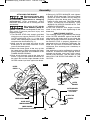
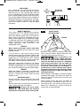
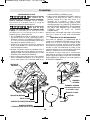
Assembly
A
TTACHING THE BLADE
Disconnect battery pack
from tool before making
any assembly, adjustments or changing
accessories. Such preventive safety
measures reduce the risk of starting the tool
accidentally.
Use only 6-1/2” blade
rated 3900/min (RPM) or
greater. Using blade not designed for the saw
may result in serious personal injury and
property damage.
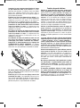
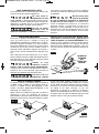
1.Turn BLADE STUD with wrench provided
clockwise and remove BLADE STUD and
OUTER WASHER (Fig. 2). If the shaft
moves while attempting to loosen the blade
stud press the lock button (Fig. 1).
2.Make sure the saw teeth and arrow on the
blade point in the same direction as the
arrow on the lower guard.
3.Retract the lower guard all the way up into
the upper guard. While retracting the lower
guard, check operation and condition of the
LOWER GUARD SPRING.
4.Slide blade through slot in the foot and
mount it against the INNER WASHER on
the shaft. Be sure the large diameter of the
OUTER washer lays flush against the blade.
5
.Reinstall OUTER WASHER and tighten
BLADE STUD finger tight. The face of upper
guard has marks around it that will help you
properly adjust the blade stud. Press lock
button to lock shaft and TIGHTEN BLADE
STUD COUNTER-CLOCKWISE TWO
MARKS ON UPPER GUARD WITH THE
WRENCH PROVIDED.
Do not use wrenches with longer handles,
since it may lead to over tightening of the
blade stud.
VARI-TORQUE CLUTCH
This clutching action is provided by the friction
of the OUTER WASHER against the BLADE
and permits the blade shaft to turn when the
blade encounters excessive resistance. When
the BLADE STUD is properly tightened (as
described in No. 5 of Attaching The Blade), the
blade will slip when it encounters ex cessive
resistance, thus reducing saw’s tendency to
KICKBACK.
One setting may not be sufficient for cutting all
materials. If ex cessive blade slippage occurs,
tighten the blade stud one mark more.
OVERTIGHTENING THE BLADE STUD
NULLIFIES THE EFFECTIVE-NESS OF THE
CLUTCH.
FIG. 2
TIGHTEN
LOOSEN
BLADE STUD
LOWER GUARD SPRING
OUTER WASHER
Large Diameter
Faces Blade
BLADE
LOWER GUARD
BLADE SHAFT
UPPER
GUARD
WRENCH
OUTER
WASHER
MARK
-10-
INNER WASHER
Large Diameter Faces Blade
2610046822.qxp_CCS180 3/23/17 1:20 PM Page 10

BEVEL ADJUSTMENT
Disconnect battery pack from tool. The foot
can be adjusted up to 50° by loosening the
bevel adjustment knob at the front of the saw.
Align to desired angle on calibrated quadrant.
Then tighten bevel adjustment knob (Fig. 7).
Because of the increased amount of blade
engagement in the work and decreased
stability of the foot, blade binding may occur.
Keep the saw steady and the foot firmly on the
workpiece.
FIG. 7
BEVEL
ADJUSTMENT
KNOB
QUADRANT
-11-
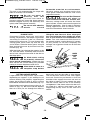
DEPTH ADJUSTMENT
Disconnect battery pack from tool. Loosen the
depth adjustment lever located on the right
side of the tool. Hold the foot down with one
hand and raise or lower saw by the handle.
Tighten lever at the depth setting desired.
Check desired depth (Fig. 3).
Not more than one tooth length of the blade
should extend below the material to be cut, for
minimum splintering (Fig. 4).
90° CUTTING ANGLE CHECK
Disconnect battery pack from tool. Set foot to
maximum depth of cut setting. Loosen bevel
adjustment lever, set to 0° on quadrant,
retighten lever and check for 90° angle
between the blade and bottom plane of foot
with a square (Fig. 5). Make adjustments by
turning the small alignment screw from bottom
side of foot, if necessary (Fig. 6).
Operating Instructions
FIG. 3 FIG. 4
FIG. 6
FIG. 5
ONE TOOTH LENGTH SHOULD
PENETRATE WOOD FOR
MINIMUM SPLINTERING
DEPTH
ADJUSTMENT
LEVER
CALIBRATED DEPTH
BRACKET
ALIGNMENT
SCREW
BEVEL
ADJUSTMENT
KNOB
BLADE
FOOT
Disconnect battery pack from tool before making any assembly,
adjustments or changing accessories. Such preventive safety measures
reduce the risk of starting the tool accidentally.
2610046822.qxp_CCS180 3/23/17 1:20 PM Page 11

-12-
LINE GUIDE
For a straight 90° cut, use left side of notch in
the foot. For 45° and 50° bevel cuts, use the
right side (Fig. 8). The cutting guide notch will
g
ive an approximate line of cut. Make sample
cuts in scrap lumber to verify actual line of cut.
This will be helpful because of the number of
different blade types and thicknesses available.
To ensure minimum splintering on the good
side of the material to be cut, face the good
side down.
SAFETY SWITCH
The safety switch is designed to prevent
accidental starts. To operate safety switch,
press the release button with your thumb on
either side of handle to disengage the lock,
then pull the trigger (Fig. 9). When the trigger
is released the button will engage the safety
switch automatically, and the trigger will no
longer operate. (See “SWITCH” and
“REGULAR CUTS”)
SWITCH
When starting the tool, hold it with both
hands. The torque from the motor can cause
the tool to twist.
To turn tool on, press the safety switch
release button with your thumb on either side
of handle to disengage the lock, then pull the
trigger (Fig. 9). To turn the tool “OFF”, release
the trigger switch, which is spring loaded and
will return to the off position automatically.
Your saw should be running at full speed
BEFORE starting the cut, and turned off only
AFTER completing the cut. To increase switch
life, do not turn switch on and off while cutting.
BRAKE
When the trigger is released it activates the
electrical brake to stop the blade quickly. This
feature is especially useful when making
repetitive cuts.
REGULAR CUTS
Always hold the saw handle with one hand
and the auxiliary handle or housing with the
other.
Always make sure saw foot rests on portion of
work surface that does not drop off.
Always be sure either
hand does not interfere
with the free movement of the lower guard.
Maintain a firm grip and operate the switch
with a decisive action. Never force the saw.
Use light and continuous pressure.
After completing a cut
and the trigger has been
released, be aware of the nec es sary time it
takes for the blade to come to a com plete
stop during coast down. Do not allow the
saw to brush against your leg or side,
since the lower guard is retractable, it
could catch on your clothing and expose
the blade. Be aware of the necessary blade
ex posures that exist in both the upper and
lower guard areas.
When cutting is interrupted, to resume cutting:
squeeze the trigger and allow the blade to
reach full speed, re-enter the cut slowly and
resume cutting.
When cutting across the grain, the fibers of
the wood have a ten den cy to tear and lift.
Advancing the saw slowly minimizes this
effect. For a finished cut, a cross cut blade or
miter blade is rec om mended.
45° AND 50°
BEVEL CUTS
90°
VERTICAL
CUTS
F
IG. 8
FIG. 9
SAFETY SWITCH
RELEASE BUTTON
TRIGGER
2610046822.qxp_CCS180 3/23/17 1:20 PM Page 12

-13-
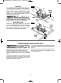
PLUNGE CUTS
Disconnect battery pack from tool before
making ad justments. Set depth adjustment
according to material to be cut. Reattach
battery pack to the saw. Tilt saw forward with
cutting guide notch lined up with the line
you’ve drawn. Raise the lower guard, using lift
lever and hold the saw by the front and rear
handles (Fig. 10).
With the blade just clearing the material to be
cut, start the motor. Gradually lower the back
end of saw using the front end of the foot as
the hinge point.
As blade starts cutting
the ma terial, release the
lower guard immediately. When the foot
rests flat on the surface being cut, proceed
cutting in forward direction to end of cut.
Allow blade to come to a
complete stop before
lifting the saw from cut. Also, never pull
the saw backward since blade will climb
out of the material and KICKBACK will
occur. Turn saw around and finish the cut in
the normal manner, sawing forward. If corners
of your pocket cut are not completely cut
through, use a jigsaw or hand saw to finish the
corners.
FIG. 11
FIG. 12
WRONG
RIGHT
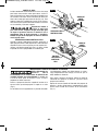
CUTTING LARGE SHEETS
Large sheets and long boards sag or bend,
depending on support. If you attempt to cut
without leveling and properly supporting the
piece, the blade will tend to bind, causing
KICK-BACK and extra load on the motor (Fig. 11).
Support the panel or board close to the cut, as
shown in (Fig. 12). Be sure to set the depth of
the cut so that you cut through the sheet or
board only and not the table or work bench.
The two-by-fours used to raise and support
the work should be positioned so that the
broadest sides support the work and rest on
the table or bench. Do not support the work
with the narrow sides as this is an unsteady
arrangement. If the sheet or board to be cut is
too large for a table or work bench, use the
supporting two-by-fours on the floor and
secure.
FIG. 10
FOOT
LOWER
GUARD
LIFT
LEVER
C
UTTING MASONRY/METAL
This tool is not recommended for usage with
metal or masonry cut-off wheels.
Do not cut metal or
masonry with this
circular saw. The dust from metal or
masonry cutting will cause the lower guard to
become sluggish and may not close fully and
quickly after cutting these materials.
Do not cut with abrasive
wheels around
f
lammable materials or environments.
Abrasive cutting may produce sparks that
could ignite flammable materials and cause
explosion hazards.
Do not use Wet Diamond
cutting off wheel or
water feed devices with this circular saw.
Masonry cutting waste will enter the lower
guard system, harden and cause the guard to
become inoperable. Use of water in masonry
cutting applications with an electric circular
saw will cause electric shock hazards.
2610046822.qxp_CCS180 3/23/17 1:20 PM Page 13

Use only Bosch batteries
recommended in the
charger Operating Instructions included with
your tool. Using other types of batteries may
result in personal injury or property damage.
Slide charged battery pack into the housing
until the battery pack locks into position
(Fig. 1).
Your tool is equipped with a secondary locking
latch to prevent the battery pack from
completely falling out of the handle, should it
become loose due to vibration.
To remove the battery pack, press the battery
pack release button and slide the battery pack
forward.
Press the battery pack release button again
and slide the battery pack completely out of
tool housing (Fig. 1).
-14-
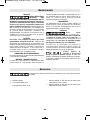
RIP CUTS
The combination blade provided with your saw
is for both cross cuts and rip cuts. Ripping is
cutting lengthwise with the grain of the wood.
Narrow rip cuts are easy to do with a rip fence
(Fig. 13). To attach fence, insert fence
through slots in foot to desired width as shown
and secure with the knob.
After attaching or
adjusting the rip fence,
be sure the rip fence does not touch or
interfere with the free movement of the
lower guard or contact the saw blade.
RIP BOARD GUIDE
When rip cutting large sheets, the rip fence
may not allow the desired width of cut. Clamp
or nail a straight piece of 1" (25 mm) lumber to
the sheet as a guide (Fig. 14). Use the right
side of the foot against the board guide.
INSERTING AND RELEASING BATTERY PACK
FIG. 13
FIG. 14
RIP
FENCE
KNOB
DESIRED
WIDTH
OF CUT
DESIRED
LINE
OF CUT
RIP
BOARD
GUIDE
2610046822.qxp_CCS180 3/23/17 1:20 PM Page 14

-15-
Accessories
(*= standard equipment)
(**= optional accessories)
* rip fence
* 6-1/2" thin kerf 18 tooth carbide blade
** 6-1/2" thin kerf 24 tooth carbide blade
Maintenance
Service
N
O USER SERVICE -
ABLE PARTS INSIDE.
Preventive maintenance performed by un -
au thorized personnel may result in
misplacing of internal wires and
components which could cause serious
hazard. We recom mend that all tool service
be performed by a Bosch Factory Service
Center or Authorized Bosch Service Station.
SERVICE MEN: Disconnect tool and/or
charger from power source before servicing.
BATTERIES
Be alert for battery packs that are nearing
their end of life. If you notice decreased tool
performance or significantly shorter running
time between charges then it is time to
replace the battery pack. Failure to do so can
cause the tool to operate improperly or
damage the charger.
TOOL LUBRICATION
Your Bosch tool has been properly lubricated
and is ready for use.
D.C. MOTORS
The motor in your tool has been engineered
for many hours of dependable service. To
maintain peak efficiency of the motor, we
r
ecommend it be examined every six
months. Only a genuine Bosch replacement
motor specially designed for your tool should
be used.
BEARINGS
Bearings which become noisy (due to heavy
load or very abrasive material cutting) should
be replaced at once to avoid overheating and
motor failure.
Cleaning
To avoid accidents,
always disconnect the
tool and/or charger from the power supply
before cleaning. The tool may be cleaned
most effectively with com pressed dry air.
Always wear safety goggles when cleaning
tools with compressed air.
Ventilation openings and switch levers must
be kept clean and free of foreign matter. Do
not attempt to clean by inserting pointed
objects through opening.
Certain cleaning agents
and solvents damage
plastic parts. Some of these are: gasoline,
car bon tetrachloride, chlorinated cleaning
solvents, ammonia and household detergents
that contain ammonia.
The use of any other acces so ries not specified in this manual may create a hazard.
2610046822.qxp_CCS180 3/23/17 1:20 PM Page 15
Page is loading ...
Page is loading ...
Page is loading ...
Page is loading ...
Page is loading ...
Page is loading ...
Page is loading ...
Page is loading ...
Page is loading ...
Page is loading ...
Page is loading ...
Page is loading ...
Page is loading ...
Page is loading ...
Page is loading ...
Page is loading ...
Page is loading ...
Page is loading ...
Page is loading ...
Page is loading ...
Page is loading ...
Page is loading ...
Page is loading ...
Page is loading ...
Page is loading ...
Page is loading ...
Page is loading ...
Page is loading ...

© Robert Bosch Tool Corporation 1800 W. Central Road Mt. Prospect, IL 60056-2230
Exportado por: Robert Bosch Tool Corporation Mt. Prospect, IL 60056-2230, E.U.A.
Importado en México por: Robert Bosch, S.A. de C.V., Calle
Robert Bosch No. 405, Zona Industrial, Toluca, Edo. de
México, C.P. 50070, Tel. (722) 2792300
L
IMITED WARRANTY OF BOSCH PORTABLE AND BENCHTOP POWER TOOLS
R
obert Bosch Tool Corporation (“Seller”) warrants to the original purchaser only, that all BOSCH portable and benchtop power tools will be free from defects in
material or workmanship for a period of one year from date of purchase. SELLER’S SOLE OBLIGATION AND YOUR EXCLUSIVE REMEDY under this Limited
Warranty and, to the extent permitted by law, any warranty or condition implied by law, shall be the repair or replacement of parts, without charge, which are
d
efective in material or workmanship and which have not been misused, carelessly handled, or misrepaired by persons other than Seller or Authorized Service
Station. To make a claim under this Limited Warranty, you must return the complete portable or benchtop power tool product, transportation prepaid, to any
BOSCH Factory Service Center or Authorized Service Station. For Authorized BOSCH Power Tool Service Stations, please refer to your phone directory.
THIS LIMITED WARRANTY DOES NOT APPLY TO ACCESSORY ITEMS SUCH AS CIRCULAR SAW BLADES, DRILL BITS, ROUTER BITS, JIGSAW BLADES,
SANDING BELTS, GRINDING WHEELS AND OTHER RELATED ITEMS.
ANY IMPLIED WARRANTIES SHALL BE LIMITED IN DURATION TO ONE YEAR FROM DATE OF PURCHASE. SOME STATES IN THE U.S., SOME CANADIAN PRO V -
I
NCES DO NOT ALLOW LIMITATIONS ON HOW LONG AN IMPLIED WARRANTY LASTS, SO THE ABOVE LIMITATION MAY NOT APPLY TO YOU.
I
N NO EVENT SHALL SELLER BE LIABLE FOR ANY INCIDENTAL OR CONSEQUENTIAL DAMAGES (INCLUDING BUT NOT LIMITED TO LIABILITY FOR LOSS OF
PROFITS) ARISING FROM THE SALE OR USE OF THIS PRODUCT. SOME STATES IN THE U.S. AND SOME CANADIAN PROVINCES DO NOT ALLOW THE
EXCLUSION OR LIMITATION OF INCIDENTAL OR CONSEQUENTIAL DAMAGES, SO THE ABOVE LIMITATION OR EXCLUSION MAY NOT APPLY TO YOU.
THIS LIMITED WARRANTY GIVES YOU SPECIFIC LEGAL RIGHTS, AND YOU MAY ALSO HAVE OTHER RIGHTS WHICH VARY FROM STATE TO STATE IN THE
U.S., PROVINCE TO PROVINCE IN CANADA AND FROM COUNTRY TO COUNTRY.
THIS LIMITED WARRANTY APPLIES ONLY TO PORTABLE AND BENCHTOP ELECTRIC TOOLS SOLD WITHIN THE UNITED STATES OF AMERICA, CANADA AND
T
HE COMMONWEALTH OF PUERTO RICO. FOR WARRANTY COVERAGE WITHIN OTHER COUNTRIES, CONTACT YOUR LOCAL BOSCH DEALER OR
IMPORTER.
GARANTIE LIMITÉE DES OUTILS ÉLECTRIQUES PORTATIFS ET D'ÉTABLI BOSCH
R
obert Bosch Tool Corporation (le « vendeur ») garantit à l'acheteur initial seulement que tous les outils électriques portatifs et d'établi BOSCH seront
exempts de vices de matériaux ou d'exécution pendant une période d'un an depuis la date d'achat. LA SEULE OBLIGATION DU VENDEUR ET LE SEUL
RECOURS DE L’ACHETEUR sous la présente garantie limitée, et en autant que la loi le permette sous toute garantie ou condition implicite qui en découlerait,
s
era l’obligation de remplacer ou réparer gratuitement les pièces défectueuses matériellement ou comme fabrication, pourvu que lesdites défectuosités ne
soient pas attribuables à un usage abusif ou à quelque réparation bricolée par quelqu’un d’autre que le vendeur ou le personnel d’une station-service agréée.
Pour présenter une réclamation en vertu de cette garantie limitée, vous devez renvoyer l'outil électrique portatif ou d'établi complet, port payé, à tout centre
d
e service agréé ou centre de service usine. Veuillez consulter votre annuaire téléphonique pour les adresses.
LA PRÉSENTE GARANTIE NE S’APPLIQUE PAS AUX ACCESSOIRES TELS QUE LAMES DE SCIES CIRCULAIRES, MÈCHES DE PERCEUSES, FERS DE
TOUPIES, LAMES DE SCIES SAUTEUSES, COURROIES DE PONÇAGE, MEULES ET AUTRES ARTICLES DU GENRE.
T
OUTE GARANTIE IMPLICITE SERA LIMITÉE COMME DURÉE À UN AN À COMPTER DE LA DATE D’ACHAT. CERTAINS ÉTATS AMÉRICAINS, CERTAINES
PROVINCES CANADIENNES N’ADMETTANT PAS LE PRINCIPE DE LA LIMITATION DE LA DURÉE DES GARANTIES IMPLICITES, IL EST POSSIBLE QUE LES
LIMITATIONS CI-DESSUS NE S’APPLIQUENT PAS À VOTRE CAS.
EN AUCUN CAS LE VENDEUR NE SAURAIT ÊTRE TENU POUR RESPONSABLE DES INCIDENTS OU DOMMAGES INDIRECTS (INCLUANT, MAIS NE SE
LIMITANT PAS AUX PERTES DE PROFITS) CONSÉCUTIFS À LA VENTE OU L’USAGE DE CE PRODUIT. CERTAINS ÉTATS AMÉRICAINS ET CERTAINES
PROVINCES CANADIENNES N’ADMETTANT PAS LE PRINCIPE DE LA LIMITATION NI L’EXCLUSION DES DOMMAGES INDIRECTS ET CONSÉQUENTIELS, IL
EST POSSIBLE QUE LES LIMITATIONS OU EXCLUSIONS CI-DESSUS NE S’APPLIQUENT PAS À VOTRE CAS.
LA PRÉSENTE GARANTIE VOUS ACCORDE DES DROITS BIEN DÉTERMINÉS, Y COMPRIS POSSIBLEMENT CERTAINS DROITS VARIABLES DANS LES
DIFFÉRENTS ÉTATS AMÉRICAINS, PROVINCES CANADIENNE ET DE PAYS À PAYS.
CETTE GARANTIE LIMITÉE NE S'APPLIQUE QU'AUX OUTILS ÉLECTRIQUES PORTATIFS ET D'ÉTABLI VENDUS AUX ÉTATS-UNIS D'AMÉRIQUE, AU CANADA
ET AU COMMONWEALTH DE PORTO RICO. POUR COUVERTURE DE GARANTIE DANS LES AUTRES PAYS, CONTACTEZ VOTRE IMPORTATEUR OU
REVENDEUR BOSCH LOCAL.
GARANTIA LIMITADA PARA HERRAMIENTAS MECANICAS PORTATILES Y PARA TABLERO DE BANCO BOSCH
Robert Bosch Tool Corporation ("el Vendedor") garantiza, únicamente al comprador original, que todas las herramientas mecánicas portátiles y para tablero
de banco BOSCH estarán libres de defectos de material o de fabricación durante un período de un año a partir de la fecha de compra. LA UNICA OBLIGACION
DEL VENDEDOR Y EL RECURSO EXCLUSIVO QUE USTED TIENE bajo esta Garantía Limitada y, hasta donde la ley lo permita, bajo cualquier garantía o
condición implícita por ley, consistirá en la reparación o sustitución sin costo de las piezas que presenten defectos de material o de fabricación y que no
hayan sido utilizadas inco rrectamente, manejadas descuidadamente o reparadas incorrectamente por personas que no sean el Vendedor o una Estación de
servicio autorizada. Para efectuar una reclamación bajo esta Garantía Limitada, usted debe devolver el producto, que consiste en la herramienta mecánica
portátil o para tablero de banco completa, con el transporte pagado, a cualquier Centro de servicio de fábrica o Estación de servicio autorizada. Para
Estaciones de servicio autorizadas de herramientas mecánicas BOSCH, por favor, consulte el directorio telefónico.
ESTA GARANTIA LIMITADA NO SE APLICA A ARTICULOS ACCESORIOS TALES COMO HOJAS PARA SIERRAS CIRCULARES, BROCAS PARA TALADROS,
BROCAS PARA FRESADORAS, HOJAS PARA SIERRAS DE VAIVEN, CORREAS PARA LIJAR, RUEDAS DE AMOLAR Y OTROS ARTICULOS RELACIONADOS.
TODAS LAS GARANTIAS IMPLICITAS TENDRAN UNA DURACION LIMITADA A UN AÑO A PARTIR DE LA FECHA DE COMPRA. ALGUNOS ESTADOS DE LOS
EE.UU. Y ALGUNAS PROVINCIAS CANADIENSES NO PERMITEN LIMITACIONES EN CUANTO A LA DURACION DE UNA GARANTIA IMPLICITA, POR LO QUE
ES POSIBLE QUE LA LIMITACION ANTERIOR NO SEA APLICABLE EN EL CASO DE USTED.
EL VENDEDOR NO SERA RESPONSABLE EN NINGUN CASO DE NINGUN DAÑO INCIDENTAL O EMERGENTE (INCLUYENDO PERO NO LIMITADO A
RESPONSABILIDAD POR PERDIDA DE BENEFICIOS) QUE SE PRODUZCA COMO CONSECUENCIA DE LA VENTA O UTILIZACION DE ESTE PRODUCTO.
ALGUNOS ESTADOS DE LOS EE.UU. Y ALGUNAS PROVINCIAS CANADIENSES NO PERMITEN LA EXCLUSION O LIMITACION DE LOS DAÑOS
INCIDENTALES O EMERGENTES, POR LO QUE ES POSIBLE QUE LA LIMITACION O EXCLUSION ANTERIOR NO SEA APLICABLE EN EL CASO DE USTED.
ESTA GARANTIA LIMITADA LE CONFIERE A USTED DERECHOS LEGALES ESPECIFICOS Y ES POSIBLE QUE USTED TAMBIEN TENGA OTROS DERECHOS QUE
VARIAN DE ESTADO A ESTADO EN LOS EE.UU., DE PROVINCIA A PROVINCIA EN CANADA Y DE UN PAIS A OTRO.
ESTA GARANTIA LIMITADA SE APLICA SOLAMENTE A HERRAMIENTAS ELECTRICAS PORTATILES Y PARA TABLERO DE BANCO VENDIDAS EN LOS
ESTADOS UNIDOS DE AMERICA, CANADA Y EL ESTADO LIBRE ASOCIADO DE PUERTO RICO. PARA COBERTURA DE GARANTIA EN OTROS PAISES,
PONGASE EN CONTACTO CON SU DISTRIBUIDOR O IMPORTADOR LOCAL DE BOSCH.
2610046822 03/17
!2610046822!
2610046822.qxp_CCS180 3/23/17 1:21 PM Page 44
-
 1
1
-
 2
2
-
 3
3
-
 4
4
-
 5
5
-
 6
6
-
 7
7
-
 8
8
-
 9
9
-
 10
10
-
 11
11
-
 12
12
-
 13
13
-
 14
14
-
 15
15
-
 16
16
-
 17
17
-
 18
18
-
 19
19
-
 20
20
-
 21
21
-
 22
22
-
 23
23
-
 24
24
-
 25
25
-
 26
26
-
 27
27
-
 28
28
-
 29
29
-
 30
30
-
 31
31
-
 32
32
-
 33
33
-
 34
34
-
 35
35
-
 36
36
-
 37
37
-
 38
38
-
 39
39
-
 40
40
-
 41
41
-
 42
42
-
 43
43
-
 44
44


Ask a question and I''ll find the answer in the document
Finding information in a document is now easier with AI
in other languages
- français: Bosch CCS180B Le manuel du propriétaire
- español: Bosch CCS180B El manual del propietario