
IMPORTANT: IMPORTANT : IMPORTANTE:
Read Before Using Lire avant usage Leer antes de usar
For English Version Version française Versión en español
See page 2 Voir page 19 Ver la página 36
Operating/Safety Instructions
Consignes de fonctionnement/sécurité
Instrucciones de funcionamiento y seguridad
1-877-BOSCH99 (1-877-267-2499) www.boschtools.com
Call Toll Free for
Consumer Information
& Service Locations
Pour obtenir des informations
et les adresses de nos centres
de service après-vente,
appelez ce numéro gratuit
Llame gratis para
obtener información
para el consumidor y
ubicaciones de servicio
1671
BM 2610945718 06-12_BM 2610945718 06-12 6/26/12 7:24 AM Page 1

-2-
'9<5+</+=+0/>C
//:A9<5+</+-6/+8+8.A/6663>Cluttered
or dark areas invite accidents.
9 89>9:/<+>/ :9A/< >996= 38 /B:69=3@/
+>79=:2/</==?-2 += 38 >2/ :</=/8-/90
06+77+,6/ 63;?3.=1+=/=9<.?=>Power
tools create sparks which may ignite the dust
or fumes.
//: -236.</8 +8. ,C=>+8./<=+A+C A236/
9:/<+>381 + :9A/< >996 Distractions can
cause you to lose control.
6/-><3-+6=+0/>C
9A/< >996 :6?1= 7?=>7+>-2 >2/ 9?>6/>
/@/<79.30C>2/:6?138+8CA+C989>
?=/ +8C +.+:>/< :6?1= A3>2 /+<>2/.
1<9?8./.:9A/< >996= Unmodified plugs
and matching outlets will reduce risk of electric
shock.
@93.,9.C-98>+->A3>2/+<>2/.9<1<9?8./.
=?<0+-/==?-2+=:3:/=<+.3+>9<=<+81/=
+8.</0<31/<+>9<=There is an increased risk
of electric shock if your body is earthed or
grounded.
989>/B:9=/:9A/<>996= >9 <+389<A/>
-98.3>398= Water entering a power tool will
increase the risk of electric shock.
989>+,?=/>2/-9<./@/<?=/>2/-9<.
09<-+<<C381:?663819<?8:6?11381>2/:9A/<
>996//:-9<.+A+C0<972/+>936=2+<:
/.1/=9<79@381:+<>=Damaged or entangled
cords increase the risk of electric shock.
'2/8 9:/<+>381 + :9A/<>996 9?>.99<=
?=/+8/B>/8=398-9<.=?3>+,6/09<9?>.99<
?=/ Use of a cord suitable for outdoor use
reduces the risk of electric shock.
09:/<+>381+:9A/<>99638+.+7:69-+>398
3=?8+@93.+,6/?=/+<9?8.+?6>3<-?3>
8>/<<?:>/<:<9>/->/.=?::6CUse of
an GFCI reduces the risk of electric shock.
/<=98+6=+0/>C
#>+C+6/<> A+>-2 A2+> C9? +</ .9381 +8.
?=/ -97798 =/8=/ A2/8 9:/<+>381+
:9A/<>996989>?=/+:9A/<>996A236/
C9?+</>3</.9<?8./<>2/3806?/8-/90.<?1=
+6-92969<7/.3-+>398A moment of inattention
while operating power tools may result in
serious personal injury.
%=/:/<=98+6:<9>/->3@//;?3:7/8>6A+C=
A/+< /C/ :<9>/->398 Protective equipment
such as dust mask, non-skid safety shoes, hard
hat, or hearing protection used for appropriate
conditions will reduce personal injuries.
</@/8>?838>/8>398+6=>+<>3818=?</>2/
=A3>-2 3= 38 >2/ 900:9=3>398 ,/09</
-988/->381>9:9A/<=9?<-/+8.9<,+>>/<C
:+-5:3-5381?: 9<-+<<C381 >2/>996
Carrying power tools with your finger on the
switch or energizing power tools that have the
switch on invites accidents.
"/79@/+8C+.4?=>3815/C9<A</8-2,/09</
>?<8381 >2/ :9A/<>99698A wrench or a
key left attached to a rotating part of the
power tool may result in personal injury.
989>9@/<</+-2//::<9:/<099>381+8.
,+6+8-/ +> +66 >37/= This enables better
control of the power tool in unexpected
situations.
</==:<9:/<6C989>A/+<699=/-69>2381
9<4/A/6<C//: C9?< 2+3<-69>2381+8.
169@/=+A+C 0<97 79@381:+<>=Loose
clothes, jewelry or long hair can be caught in
moving parts.
0./@3-/=+</:<9@3./. 09<>2/-988/->398
90.?=> /B><+->398+8.-966/->3980+-363>3/=
/8=?</>2/=/+</-988/->/. +8. :<9:/<6C
?=/.Use of dust collection can reduce dust-
related hazards.
9A/<>996?=/+8.-+</
9 89> 09<-/ >2/ :9A/< >996 %=/ >2/
-9<</->:9A/< >99609<C9?<+::63-+>398The
correct power tool will do the job better and
safer at the rate for which it was designed.
989>?=/>2/:9A/<>99630>2/=A3>-2.9/=
89> >?<8 3> 98 +8. 900Any power tool that
cannot be controlled with the switch is
dangerous and must be repaired.
"/+.+66=+0/>CA+<8381=+8.+6638=><?->398=Failure to follow the warnings
and instructions may result in electric shock, fire and/or serious injury.
#&'"##$"%$#"%$%"""
The term “power tool” in the warnings refers to your mains-operated (corded) power tool or
battery-operated (cordless) power tool.
!
WARNING
/8/<+6 9A/<$996#+0/>C'+<8381=
BM 2610945718 06-12_BM 2610945718 06-12 6/26/12 7:24 AM Page 2

-3-
3=-988/->>2/:6?10<97>2/:9A/<=9?<-/
+8.9<>2/,+>>/<C:+-50<97>2/:9A/<>996
,/09</ 7+5381+8C +.4?=>7/8>=-2+81381
+--/==9<3/= 9< =>9<381:9A/<>996=Such
preventive safety measures reduce the risk of
starting the power tool accidentally.
#>9</3.6/:9A/<>996=9?>90>2/ </+-290
-236.</8+8..989>+669A:/<=98=?80+7363+<
A3>2>2/:9A/<>9969<>2/=/38=><?->398=>9
9:/<+>/ >2/ :9A/<>996 Power tools are
dangerous in the hands of untrained users.
+38>+38:9A/<>996=2/-509<73=+63187/8>
9<,38.381 90 79@381 :+<>= ,</+5+1/90
:+<>=+8.+8C9>2/<-98.3>398>2+> 7+C
+00/->>2/:9A/<>996I=9:/<+>3980.+7+1/.
2+@/ >2/ :9A/<>996 </:+3</. ,/09</ ?=/
Many accidents are caused by poorly
maintained power tools.
//:-?>>381>996==2+<:+8.-6/+8Properly
maintained cutting tools with sharp cutting
edges are less likely to bind and are easier to
control.
%=/>2/ :9A/< >996 +--/==9<3/=+8.>996
,3>=/>-38+--9<.+8-/A3>2>2/=/38=><?->398=
>+538138>9+--9?8>>2/A9<5381-98.3>398=
+8.>2/ A9<5 >9,/ :/<09<7/.Use of the
power tool for operations different from those
intended could result in a hazardous situation.
+>>/<C>996?=/+8.-+</
"/-2+<1/986C A3>2 >2/-2+<1/<=:/-303/.
,C >2/ 7+8?0+->?</< A charger that is
suitable for one type of battery pack may
create a risk of fire when used with another
battery pack.
%=/ :9A/< >996= 986C A3>2 =:/-303-+66C
./=318+>/.,+>>/<C:+-5= Use of any other
battery packs may create a risk of injury and
fire.
'2/8,+>>/<C :+-53= 89> 38?=/ 5//: 3>
+A+C 0<97 9>2/<7/>+6 9,4/->= 635/ :+:/<
-63:= -938= 5/C=8+36= =-</A= 9< 9>2/<
=7+66 7/>+6 9,4/->= >2+> -+87+5/ +
-988/->3980<97 98/ >/<738+6>9+89>2/<
Shorting the battery terminals together may
cause burns or a fire.
%8./< +,?=3@/ -98.3>398= 63;?3. 7+C ,/
/4/->/.0<97>2/,+>>/<C +@93.-98>+->0
-98>+->+--3./8>+66C 9--?<= 06?=2A3>2
A+>/<063;?3.-98>+->=/C/=+..3>398+66C
=//5 7/.3-+6 2/6: Liquid ejected from the
battery may cause irritation or burns.
#/<@3-/
+@/C9?<:9A/<>996=/<@3-/.,C+;?+6303/.
</:+3< :/<=98 ?=381 986C 3./8>3-+6
</:6+-/7/8> :+<>= This will ensure that the
safety of the power tool is maintained.
#+0/>C"?6/=09<3<-?6+<#+A=
"/+.+66=+0/>CA+<8381=+8.+6638=><?->398=
!
WARNING
?>>381:<9-/.?</=
//: 2+8.= +A+C 0<97
-?>>381+</++8. >2/,6+./
//:C9?<=/-98.2+8.98+?B363+<C2+8.6/
9<79>9<29?=381 If both hands are holding
the saw, they cannot be cut by the blade.
9 89></+-2 ?8./<8/+>2>2/A9<5:3/-/
The guard cannot protect you from the blade
below the workpiece.
.4?=>>2/-?>>381./:>2>9>2/>23-58/==90
>2/A9<5:3/-/Less than a full tooth of the
blade teeth should be visible below the
workpiece.
/@/<296.:3/-/,/381-?>38C9?<2+8.=
9<+-<9==C9?<6/1 #/-?</>2/A9<5:3/-/>9
=>+,6/:6+>09<7 It is important to support the
work properly to minimize body exposure,
blade binding, or loss of control.
96.:9A/<>996,C38=?6+>/. 1<3::381
=?<0+-/=A2/8 :/<09<7381 +8 9:/<+>398
A2/</ >2/ -?>>381>9967+C-98>+-> 23../8
A3<381 Contact with a "live" wire will also make
exposed metal parts of the tool “live” and shock
the operator.
'2/8<3::381 +6A+C=?=/ + <3: 0/8-/9<
=><+312>/.1/ 1?3./ This improves the
accuracy of cut and reduces the chance for
blade binding.
6A+C= ?=/,6+./= A3>2 -9<</-> =3D/+8.
=2+:/ .3+798.@/<=?= <9?8. 90 +<,9<
296/=Blades that do not match the mounting
hardware of the saw will run eccentrically,
causing loss of control.
!
DANGER
BM 2610945718 06-12_BM 2610945718 06-12 6/26/12 7:24 AM Page 3

-4-
/@/< ?=/.+7+1/. 9<38-9<</->,6+./
A+=2/<=9<,96> The blade washers and bolt
were specially designed for your saw, for
optimum performance and safety of operation.
$23=:<9.?->3=38>/8./.>9-?>A99.+8.
A99.635/ :<9.?->= 986C. Dust build up
around the lower guard and hub from other
materials (plastic, masonry or metal) may
disable the lower guard operation.
8=:/-> >2/-98.3>398+8. ;?+63>C90>2/
A99. +8.</79@/ +668+36=0<97 6?7,/<
,/09</-?>>381Wet lumber, green lumber or
pressure treated lumber require special
attention during cutting operation to prevent
kickback.
96.>2/=+A03<76C >9:</@/8> 69==90
-98><96Figures in this manual illustrate
typical hand support of the saw.
/:/8.381?:98?=/>2/=A3>-27+C89>
6+=>>2/630/90>2/=+A0>2/=A3>-2=29?6.
0+3638>2/FG:9=3>398>2/=+A7+C89>
=>+<> 03> =29?6.0+36 A236/>2/ =+A3=
<?88381>2/=+A7+C89>=2?>900 If either
occurs, unplug the saw immediately and do
not use until repaired.
$23=-3<-?6+<=+A=29?6.89>,/79?8>/.>9
+ >+,6/ +8. -98@/<>/.>9 + >+,6/ =+A
Circular saws are not designed or intended to
be used as table saws.
3-5,+-5+8.</6+>/.A+<8381=
+?=/=+8.9:/<+>9<:</@/8>39890
53-5,+-5
Kickback is a sudden reaction to a pinched,
bound or misaligned saw blade, causing an
uncontrolled saw to lift up and out of the
workpiece toward the operator.
When the blade is pinched or bound tightly by
the kerf closing down, the blade stalls and the
motor reaction drives the unit rapidly back
toward the operator.
If the blade becomes twisted or misaligned in
the cut, the teeth at the back edge of the blade
can dig into the top surface of the wood
causing the blade to climb out of the kerf and
jump back toward the operator.
Kickback is the result of tool misuse and/or
incorrect operating procedures or conditions
and can be avoided by taking proper
precautions as given below:
+38>+38+03<71<3:A3>2,9>22+8.=98>2/
=+A+8.:9=3>398 C9?< +<7= >9 </=3=>
53-5,+-5 09<-/= 9=3>398 C9?< ,9.C >9
/3>2/<=3./90>2/,6+./,?>89>38638/A3>2
>2/,6+./ Kickback could cause the saw to
jump backwards, but kickback forces can be
controlled by the operator, if proper
precautions are taken.
'2/8,6+./3=,38.3819<A2/838>/<<?:>381
+-?>09<+8C</+=98</6/+=/>2/><311/<+8.
296.>2/ =+A79>3986/==38 >2/ 7+>/<3+6
?8>36>2/,6+./-97/=>9+-97:6/>/ =>9:
/@/<+>>/7:>>9</79@/>2/=+A0<97 >2/
A9<5 9< :?66>2/ =+A ,+-5A+<. A236/ >2/
,6+./3= 38 79>3989<53-5,+-57+C 9--?<
Investigate and take corrective action to
eliminate the cause of blade binding.
'2/8 </=>+<>381+=+A 38 +A9<5:3/-/
-/8>/<>2/=+A,6+./38>2/5/<0+8.-2/-5
>2+>=+A >//>2 +</ 89>/81+1/.38>9>2/
7+>/<3+6 If saw blade is binding, it may walk
up or kickback from the workpiece as the saw
is restarted.
#?::9<>6+<1/:+8/6=>9738373D/>2/<3=590
,6+./ :38-2381+8. 53-5,+-5 Large panels
tend to sag under their own weight. Supports
must be placed under the panel on both sides,
near the line of cut and near the edge of the
panel.
9 89> ?=/ .?66 9< .+7+1/. ,6+./=
Unsharpened or improperly set blades
produce narrow kerf causing excessive friction,
blade binding and kickback.
6+./ ./:>2 +8. ,/@/6+.4?=>381 69-5381
6/@/<=7?=> ,/ >312>+8.=/-?</,/09</
7+5381-?> If blade adjustment shifts while
cutting, it may cause binding and kickback.
%=//B><+-+?>398A2/8 7+5381+F 6?81/
?>G38>9/B3=>381 A+66= 9<9>2/<,638.
+</+= The protruding blade may cut objects
that can cause kickback.
$2/,6+./ A+=2/<= +8. >2/ ,96> 98 C9?<
=+A 2+@/ ,//8./=318/. >9A9<5 += +
-6?>-2>9</.?-/>2/38>/8=3>C90+53-5,+-5
%8./<=>+8.>2/9:/<+>398+8.=/>>381=90
>2/ &"$"!% %$ The proper
setting of the clutch, combined with firm
handling of the saw will allow you to control
kickback.
/@/<:6+-/C9?<2+8. ,/238.>2/ =+A
,6+./Kickback could cause the saw to jump
backwards over your hand.
989> ?=/ >2/ =+A A3>2 +8/B-/==3@/
./:>2 90 -?> =/>>381 Too much blade
exposure increases the likelihood of the blade
twisting in the kerf and increases the surface
area of the blade available for pinching that
leads to kickback.
BM 2610945718 06-12_BM 2610945718 06-12 6/26/12 7:24 AM Page 4

9A/<1?+<.0?8->398
2/-5 69A/<1?+<. 09< :<9:/<-69=381
,/09</ /+-2 ?=/ 9 89>9:/<+>/ =+A 30
69A/< 1?+<. .9/=89>79@/ 0<//6C +8.
-69=/ 38=>+8>6C/@/<-6+7: 9< >3/ >2/
69A/<1?+<.38>9>2/9:/8:9=3>398 If saw is
accidentally dropped, lower guard may be
bent. Raise the lower guard only with the lower
guard lift lever and make sure it moves freely
and does not touch the blade or any other part,
in all angles and depths of cut.
2/-5 >2/ 9:/<+>39890>2/69A/< 1?+<.
=:<3810>2/1?+<.+8.>2/=:<381+</89>
9:/<+>381:<9:/<6C >2/C 7?=> ,/=/<@3-/.
,/09</ ?=/ Lower guard may operate
sluggishly due to damaged parts, gummy
deposits, or a buildup of debris.
9A/<1?+<.=29?6. ,/</><+->/.7+8?+66C
986C09< =:/-3+6 -?>= =?-2+= F 6?81/
?>=G +8.F97:9?8. ?>=G "+3=/69A/<
1?+<.,C69A/<1?+<.630>6/@/<+8.+==998
+=,6+./ /8>/<= >2/ 7+>/<3+6 69A/< 1?+<.
7?=>,/</6/+=/. For all other sawing, the
lower guard should operate automatically.
6A+C= 9,=/<@/>2+> >2/ 69A/<1?+<.3=
-9@/<381>2/ ,6+./,/09</ :6+-381 =+A
.9A8 98,/8-29<0699< An unprotected,
coasting blade will cause the saw to walk
backwards, cutting whatever is in its path. Be
aware of the time it takes for the blade to stop
after switch is released.
989><?8>2/>996A236/-+<<C3813>+>C9?<
=3./9A/<1?+<.7+C,/ 9:/8/.,C +
-98>+->A3>2C9?< -69>2381 Accidental
contact with the spinning saw blade could
result in serious personal injury.
/<39.3-+66C </79@/>2/,6+./ -6/+8 >2/
?::/<69A/<1?+<.=+8.>2/2?,+</+A3>2
5/<9=/8/+8.A3:/3>.<C9<,69A3>-6/+8
A3>2-97:</==/.+3<Preventive maintenance
and properly operating guard will reduce the
probability of an accident.
-5-
KICKBACK
GFCI and personal protection devices like
electrician’s rubber gloves and footwear will
further enhance your personal safety.
989> ?=/986C<+>/. >996=A3>2 +
:9A/< =?::6CWhile the tool may appear to
work, the electrical components of the AC
rated tool are likely to fail and create a hazard
to the operator.
//: 2+8.6/=.<C-6/+8+8.0<//0<97936
+8. 1</+=/ Slippery hands cannot safely
control the power tool.
/@/69:+:/<39.3-7+38>/8+8-/=-2/.?6/
09<C9?< >996 '2/8 -6/+8381 +>996,/
-+</0?689>>9.3=+==/7,6/+8C:9<>39890
>2/ >996 =38-/ 38>/<8+6 A3</= 7+C ,/
73=:6+-/.9<:38-2/.9<=+0/>C1?+<.</>?<8
=:<381= 7+C ,/ 37:<9:/<6C 79?8>/.
Certain cleaning agents such as gasoline,
carbon tetrachloride, ammonia, etc. may
damage plastic parts.
8=?</ >2/ =A3>-2 3= 38 >2/ 900 :9=3>398
,/09</38=/<>381,+>>/<C:+-5 Inserting the
battery pack into power tools that have the
switch on invites accidents.
#97/.?=>-</+>/.,C:9A/<
=+8.381=+A381 1<38.381
.<366381 +8. 9>2/<-98=><?->398 +->3@3>3/=
-98>+38=-2/73-+6=589A8>9-+?=/-+8-/<
,3<>2 ./0/->= 9< 9>2/<</:<9.?->3@/2+<7
#97//B+7:6/=90>2/=/-2/73-+6=+</
• Lead from lead-based paints,
• Crystalline silica from bricks and cement and
other masonry products, and
• Arsenic and chromium from chemically-
treated lumber.
Your risk from these exposures varies,
depending on how often you do this type of
work. To reduce your exposure to these
chemicals: work in a well ventilated area, and
work with approved safety equipment, such as
those dust masks that are specially designed
to filter out microscopic particles.
..3>398+6#+0/>C'+<8381=
!
WARNING
BM 2610945718 06-12_BM 2610945718 06-12 6/26/12 7:24 AM Page 5

+>>/<C+</
/09</ ?=381 ,+>>/<C
-2+<1/< </+. +66
38=><?->398=+8.-+?>398+<C 7+<5381= 98
,+>>/<C-2+<1/<,+>>/<C:+-5+8.
:<9.?->?=381,+>>/<C
%=/986C>2/-2+<1/< A23-2+--97:+83/.
C9?<:<9.?-> 9<.3</-> </:6+-/7/8> +=
63=>/.38>2/-+>+6919<>23=7+8?+6 Do not
substitute any other charger. Use only Bosch
approved chargers with your product. See
Functional Description and Specifications.
989>.3=+==/7,6/-2+<1/<9<9:/<+>/>2/
-2+<1/< 30 3> 2+=</-/3@/.+ =2+<: ,69A
,//8 .<9::/. 9< 9>2/<A3=/ .+7+1/.38
+8CA+C "/:6+-/.+7+1/.-9<. 9< :6?1=
377/.3+>/6C Incorrect reassembly or
damage may result in electric shock or fire.
989> </-2+<1/ ,+>>/<C 38 .+7: 9< A/>
/8@3<987/8> 9 89> /B:9=/ -2+<1/<>9
<+389<=89A0,+>>/<C -+=/3=-<+-5/.9<
9>2/<A3=/.+7+1/. .9 89> 38=/<> 38>9
-2+<1/< Battery short or fire may result.
2+<1/986C9=-2+::<9@/.</-2+<1/+,6/
,+>>/<3/= See Functional Description and
Specifications. Other types of batteries may
burst causing personal injury and damage.
2+<1/,+>>/<C:+-538>/7:/<+>?</=+,9@/
./1<//= ./1<//= +8. ,/69A
./1<//=./1<//=#>9</>996
+8. ,+>>/<C :+-5 38 69-+>398= A2/</
>/7:/<+>?</= .989>19,/69A ./1<//=
./1<//= 9< A36689 /B-//.
./1<//= ./1<//= 669A,+>>/<C
:+-5>9</>?<8>9<997>/7:/<+>?</,/09</
+>>/7:>381>9 -2+<1/This is important to
prevent serious damage to the battery cells.
+>>/<C 6/+5+1/7+C 9--?< ?8./< /B></7/
?=+1/ 9< >/7:/<+>?</ -98.3>398= @93.
-98>+-> A3>2 =538 +8. /C/= The battery
liquid is caustic and could cause chemical
burns to tissues. If liquid comes in contact with
skin, wash quickly with soap and water, then
with lemon juice or vinegar. If the liquid
contacts your eyes, flush them with water for a
minimum of 10 minutes and seek medical
attention.
6+-/ -2+<1/< 98 06+> 89806+77+,6/
=?<0+-/= +8. +A+C 0<97 06+77+,6/
7+>/<3+6=A2/8 </-2+<1381,+>>/<C:+-5
The charger and battery pack heat during
charging. Carpeting and other heat insulating
surfaces block proper air circulation which
may cause overheating of the charger and
battery pack. If smoke or melting of the case
are observed unplug the charger immediately
and do not use the battery pack or charger.
%=/ 90 +8 +>>+-27/8> 89> </-97
7/8./. 9<=96. ,C9=-27+C</=?6>38+
<3=590 03</ /6/-><3- =29-5 9< 384?<C>9
:/<=98=
-6-
'2/8 ,+>>/<3/= +</ 89> 38
>9969<-2+<1/< 5//:>2/7
+A+C 0<97 7/>+69,4/->= For example, to
protect terminals from shorting H$ place
batteries in a tool box or pocket with nails,
screws, keys, etc. Fire or injury may result.
$ %$ $$"# $ ""
( # $ $ They may
explode.
+>>/<C2+<1/<
!
WARNING
!
WARNING
BM 2610945718 06-12_BM 2610945718 06-12 6/26/12 7:24 AM Page 6

-7-
9 89> +>>/7:> >9 .3=+=
=/7,6/ >2/ ,+>>/<C 9<
</79@/+8C -97:98/8>:<94/->381 0<97
>2/ ,+>>/<C >/<738+6= Fire or injury may
result. Prior to disposal, protect exposed
terminals with heavy insulating tape to
prevent shorting.
$%$$"#
If equipped with a lithium-ion battery, the battery
must be collected, recycled or disposed of in
an environ mentally sound manner.
“The EPA certified RBRC
Battery Recycling Seal on the
lithium-ion (Li-ion) battery
indicates Robert Bosch Tool
Corporation is voluntarily
participating in an industry
program to collect and recycle these batteries
at the end of their useful life, when taken out
of service in the United States or Canada. The
RBRC program provides a convenient
alterative to placing used Li-ion batteries into
the trash or the munici pal waste stream, which
may be illegal in your area.
Please call 1-800-8-BATTERY for information
on Li-ion battery recycling and disposal
bans/restrictions in your area, or return your
batteries to a Skil/Bosch/Dremel Service
Center for recycling. Robert Bosch Tool
Corporation’s involvement in this program is
part of our commitment to preserving our
environment and conserving our natural
resources.”
!
WARNING
+>>/<C3=:9=+6
BM 2610945718 06-12_BM 2610945718 06-12 6/26/12 7:24 AM Page 7

-8-
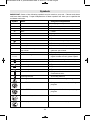
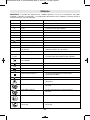
"$$ Some of the following symbols may be used on your tool. Please study them
and learn their meaning. Proper interpretation of these symbols will allow you to operate the
tool better and safer.
#C7,96 +7/ /=318+>398B:6+8+>398
V Volts Voltage (potential)
A Amperes Current
Hz Hertz Frequency (cycles per second)
W Watt Power
kg Kilograms Weight
min Minutes Time
s Seconds Time
Diameter Size of drill bits, grinding wheels, etc.
n
0
No load speed Rotational speed, at no load
n Rated speed Maximum attainable speed
.../min Revolutions or reciprocation Revolutions, strokes, surface speed,
per minute orbits etc. per minute
0 Off position Zero speed, zero torque...
1, 2, 3, ... Selector settings Speed, torque or position settings.
I, II, III, Higher number means greater speed
Infinitely variable selector with off Speed is increasing from 0 setting
Arrow Action in the direction of arrow
Alternating current Type or a characteristic of current
Direct current Type or a characteristic of current
Alternating or direct current Type or a characteristic of current
Class II construction Designates Double Insulated
Construction tools.
Earthing terminal Grounding terminal
Warning symbol Alerts user to warning messages
Li-ion RBRC seal Designates Li-ion battery recycling
program
Ni-Cad RBRC seal Designates Ni-Cad battery recycling
program
Read manual symbol Alerts user to read manual
Wear eye protection symbol Alerts user to wear eye protection
#C7,96=
0
BM 2610945718 06-12_BM 2610945718 06-12 6/26/12 7:24 AM Page 8

-9-
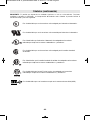
This symbol designates that this tool is listed by Underwriters Laboratories.
This symbol designates that this tool is listed by the Canadian Standards
Association.
This symbol designates that this tool is listed by the Canadian Standards
Association, to United States and Canadian Standards.
This symbol designates that this tool complies to NOM Mexican Standards.
This symbol designates that this tool is listed by the Intertek Testing
Services, to United States and Canadian Standards.
#C7,96=-98>38?/.
"$$ Some of the following symbols may be used on your tool. Please study them
and learn their meaning. Proper interpretation of these symbols will allow you to operate the
tool better and safer.
This symbol designates that this tool is recognized by Underwriters Laboratories.
This symbol designates that this tool is listed by Underwriters Laboratories,
to United States and Canadian Standards.
BM 2610945718 06-12_BM 2610945718 06-12 6/26/12 7:24 AM Page 9

-10-
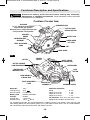
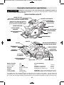
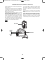
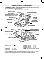
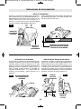
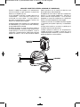
?8->398+6/=-<3:>398+8.#:/-303-+>398=
FOOT
LOWER GUARD
LIFT LEVER
AUXILIARY
HANDLE
BEVEL ADJUSTMENT
KNOB
CALIBRATED BEVEL
QUADRANT
3=-988/-> ,+>>/<C :+-50<97 >996 ,/09</7+5381 +8C +==/7,6C
+.4?=>7/8>= 9<-2+81381+--/==9<3/=. Such preventive safety measures
reduce the risk of starting the tool accidentally.
!
WARNING
9<.6/==3<-?6+<#+A
UPPER GUARD
LOWER GUARD
LOCK
BUTTON
FIG. 1
BATTERY PACK
SAFETY SWITCH
RELEASE BUTTON
TRIGGER
SWITCH
BLADE WRENCH &
STORAGE AREA
VENTILATION
OPENINGS
9./69 1671
Voltage rating 36 V
No load speed n
0
4,000/min
+>>/<C:+-5 BAT818 & BAT836
2+<1/< BC830
Charge time 1 hr/45 min.
Voltage rating 120 V 60 Hz
For replacement blades we recommend Bosch Cordless Circular saw blades. Their thin kerf and
tooth design deliver the best speed, quality of cut, and reduce battery drain. Use of standard blades
will substantially affect the performance and reduce run-time.
+B37?7+:+-3>3/=
Blade 6-1/2"
Depth of cut at 90° 2-1/8"
Depth of cut at 45° 1-3/4"
Depth of cut at 50° 1-1/2"
$$$ Use only thin kerf blades
designed for Cordless Circular Saws.
SAW HOOK
To use, simply lift up hook until it
snaps into the open position.
When not in use, always lower hook until
it snaps into the closed position.
RUBBERIZED GRIP
DEPTH ADJUSTMENT
LEVER
ALIGNMENT SCREW
BATTERY PACK
RELEASE BUTTON
BUTTON
BATTERY CHARGED
CONDITION INDICATOR
TEMPERATURE
INDICATOR LIGHT
BM 2610945718 06-12_BM 2610945718 06-12 6/26/12 7:24 AM Page 10

-11-
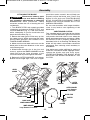
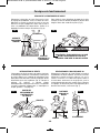
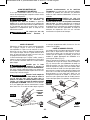
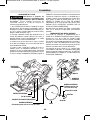
==/7,6C
$$$
3=-988/->,+>>/<C :+-5
0<97 >996 ,/09</ 7+5381
+8C +==/7,6C +.4?=>7/8>= 9<-2+81381
+--/==9<3/=. Such preventive safety
measures reduce the risk of starting the tool
accidentally.
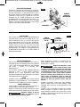
1. Turn BLADE STUD with wrench provided
clockwise and remove BLADE STUD and
OUTER WASHER (Fig. 2). If the shaft moves
while attempting to loosen the blade stud
press the lock button (Fig. 1).
2. Retract the lower guard all the way up into
the upper guard. While retracting the lower
guard, check operation and condition of the
LOWER GUARD SPRING.
3. Make sure the saw teeth and arrow on the
blade point in the same direction as the arrow
on the lower guard.
4. Slide blade through slot in the foot and
mount it against the INNER WASHER on the
shaft. Be sure the large diameter of the
OUTER washer lays flush against the blade.
5. Reinstall OUTER WASHER and tighten
BLADE STUD finger tight. The face of upper
guard has marks around it that will help you
properly adjust the blade stud. Press lock
button to lock shaft and TIGHTEN BLADE
STUD COUNTER-CLOCKWISE THREE
MARKS ON UPPER GUARD WITH THE
WRENCH PROVIDED.
Do not use wrenches with longer handles,
since it may lead to over tightening of the
blade stud.
&"$"!%%$
This clutching action is provided by the friction
of the OUTER WASHER against the BLADE
and permits the blade shaft to turn when the
blade encounters excessive resistance. When
the BLADE STUD is properly tightened (as
described in No. 5 of Attaching The Blade), the
blade will slip when it encounters ex cessive
resistance, thus reducing saw’s tendency to
KICKBACK.
One setting may not be sufficient for cutting all
materials. If ex cessive blade slippage occurs,
tighten the blade stud one mark more.
OVERTIGHTENING THE BLADE STUD
NULLIFIES THE EFFECTIVE-NESS OF THE
CLUTCH.
!
WARNING
FIG. 2
TIGHTEN
LOOSEN
BLADE STUD
LOWER GUARD SPRING
OUTER WASHER
Large Diameter
Faces Blade
INNER WASHER
Large Diameter Faces Blade
BLADE
LOWER GUARD
BLADE SHAFT
UPPER
GUARD
WRENCH
OUTER
WASHER
MARK
BM 2610945718 06-12_BM 2610945718 06-12 6/26/12 7:24 AM Page 11

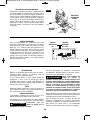
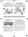
-12-
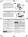
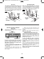
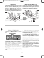
Disconnect battery pack from tool. Loosen the
depth adjustment lever located on the right
side of the tool. Hold the foot down with one
hand and raise or lower saw by the handle.
Tighten lever at the depth setting desired.
Check desired depth (Fig. 3).
Not more than one tooth length of the blade
should extend below the material to be cut, for
minimum splintering (Fig. 4).
#$)#'$
The safety switch is designed to prevent
accidental starts. To operate safety switch,
press the release button with your thumb on
either side of handle to disengage the lock,
then pull the trigger (Fig. 5). When the trigger
is released the button will engage the safety
switch automatically, and the trigger will no
longer operate. (See Switch & General Cuts
on page 12.)
E%$$
Disconnect battery pack from tool. Set foot to
maximum depth of cut setting. Loosen bevel
adjustment lever, set to 0° on quadrant,
retighten lever and check for 90° angle
between the blade and bottom plane of foot
with a square (Fig. 6). Make adjustments by
turning the small alignment screw from bottom
side of foot, if necessary (Fig. 7).
$%#$$
:/<+>3818=><?->398=
2x
FIG. 3
FIG. 4
FIG. 5
FIG. 7
FIG. 6
ONE TOOTH LENGTH SHOULD
PENETRATE WOOD FOR
MINIMUM SPLINTERING
DEPTH
ADJUSTMENT LEVER
CALIBRATED
DEPTH
BRACKET
SAFETY SWITCH
RELEASE BUTTON
ALIGNMENT
SCREW
BEVEL
ADJUSTMENT
KNOB
BLADE
TRIGGER
FOOT
BM 2610945718 06-12_BM 2610945718 06-12 6/26/12 7:24 AM Page 12

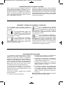
&%#$$
Disconnect battery pack from tool. The foot
can be adjusted up to 50° by loosening the
bevel adjustment knob at the front of the saw.
Align to desired angle on calibrated quadrant.
Then tighten bevel adjustment knob (Fig. 8).
Because of the increased amount of blade
engagement in the work and decreased
stability of the foot, blade binding may occur.
Keep the saw steady and the foot firmly on the
workpiece.
-13-
%
For a straight 90° cut, use left side of notch in
the foot. For 45° & 50° bevel cuts, use the right
side (Fig. 9). The cutting guide notch will give
an approximate line of cut. Make sample cuts in
scrap lumber to verify actual line of cut. This will
be helpful because of the number of different
blade types and thicknesses available. To
ensure minimum splintering on the good side of
the material to be cut, face the good side down.
#'$
To turn tool “ON”, squeeze the trigger switch.
To turn the tool “OFF”, release the trigger
switch, which is spring loaded and will return
to the off position automatically.
Your saw should be running at full speed
BEFORE starting the cut, and turned off only
AFTER completing the cut. To increase switch
life, do not turn switch on and off while cutting.
"
When the trigger is released it activates the
electrical brake to stop the blade quickly. This
feature is especially useful when making
repetitive cuts.
"%$#
Always hold the saw handle with one hand
and the auxiliary handle or housing with the
other.
Always make sure saw foot rests on portion of
work surface that does not drop off.
6A+C=,/=?<//3>2/<2+8.
.9/=89> 38>/<0/</ A3>2>2/
0<//79@/7/8>90>2/69A/<1?+<.
Maintain a firm grip and operate the switch
with a decisive action. Never force the saw.
Use light and continuous pressure.
0>/<-97:6/>381 + -?>+8.
>2/ ><311/< 2+= ,//8
</6/+=/.,/+A+</90>2/8/-/==+<C>37/3>
>+5/=09<>2/,6+./>9-97/>9+-97:6/>/
=>9:.?<381-9+=>.9A8989> +669A>2/
=+A >9 ,<?=2 +1+38=>C9?< 6/1 9<=3./
=38-/ >2/69A/<1?+<. 3= </><+->+,6/3>
-9?6.-+>-298C9?< -69>2381+8./B:9=/
>2/,6+.//+A+</90>2/8/-/==+<C,6+./
/B:9=?</=>2+>/B3=>38,9>2>2/?::/<+8.
69A/<1?+<.+</+=
When cutting is interrupted, to resume cutting:
squeeze the trigger and allow the blade to
reach full speed, re-enter the cut slowly and
resume cutting.
When cutting across the grain, the fibers of
the wood have a ten den cy to tear and lift.
Advancing the saw slowly minimizes this
effect. For a finished cut, a cross cut blade or
miter blade is rec om mended.
!
WARNING
!
WARNING
FIG. 8
BEVEL
ADJUSTMENT
KNOB
QUADRANT
45° & 50°
BEVEL CUTS
90°
VERTICAL CUTS
FIG. 9
BM 2610945718 06-12_BM 2610945718 06-12 6/26/12 7:24 AM Page 13

-14-
%$$#")$
This tool is not recommended for usage with
metal or masonry cut-off wheels.
9 89> -?> 7/>+6 9<
7+=98<C A3>2 >23=-3<-?6+<
=+A The dust from metal or masonry cutting
will cause the lower guard to become sluggish
and may not close fully and quickly after
cutting these materials.
9 89> -?> A3>2+,<+=3@/
A2//6= +<9?8. 06+77+,6/
7+>/<3+6=9</8@3<987/8>= Abrasive cutting
may produce sparks that could ignite
flammable materials and cause explosion
hazards.
9 89> ?=/ '/>3+798.
-?>>381 900 A2//6 9<A+>/<
0//. ./@3-/= A3>2 >23= -3<-?6+< =+A
Masonry cutting waste will enter the lower
guard system, harden and cause the guard to
become inoperable. Use of water in masonry
cutting applications with an electric circular
saw will cause electric shock hazards.
!
WARNING
!
WARNING
!
WARNING
%%$#
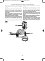
Disconnect battery pack from tool before
making ad justments. Set depth adjustment
according to material to be cut. Tilt saw
forward with cutting guide notch lined up with
the line you’ve drawn. Raise the lower guard,
using lift lever and hold the saw by the front
and rear handles (Fig. 10).
With the blade just clearing the material to be
cut, start the motor. Gradually lower the back
end of saw using the front end of the foot as
the hinge point.
=,6+./=>+<>=-?>>381>2/
7+>/<3+6</6/+=/ >2/ 69A/<
1?+<.377/.3+>/6C When the foot rests flat
on the surface being cut, proceed cutting in
forward direction to end of cut.
'" 669A ,6+./ >9
-97/ >9+-97:6/>/=>9:
,/09</630>381>2/=+A0<97-?> 6=98/@/<
:?66>2/ =+A ,+-5A+<. =38-/ ,6+./ A366
-637, 9?> 90 >2/ 7+>/<3+6 +8.
A3669--?< Turn saw around and finish the cut
in the normal manner, sawing forward. If
corners of your pocket cut are not completely
cut through, use a jigsaw or hand saw to finish
the corners.
%$$"#$#
Large sheets and long boards sag or bend,
depending on support. If you attempt to cut
without leveling and properly supporting the
piece, the blade will tend to bind, causing
KICK-BACK and extra load on the motor (Fig. 11).
Support the panel or board close to the cut, as
shown in (Fig. 12). Be sure to set the depth of
the cut so that you cut through the sheet or
board only and not the table or work bench.
The two-by-fours used to raise and support
the work should be positioned so that the
broadest sides support the work and rest on
the table or bench. Do not support the work
with the narrow sides as this is an unsteady
arrangement. If the sheet or board to be cut is
too large for a table or work bench, use the
supporting two-by-fours on the floor and
secure.
!
WARNING
!
WARNING
FIG. 10
FIG. 11
FIG. 12
WRONG
RIGHT
FOOT
LOWER
GUARD
LIFT
LEVER
BM 2610945718 06-12_BM 2610945718 06-12 6/26/12 7:24 AM Page 14

$$")"$
$"
The battery is equipped with a charged
condition indicator.
By pressing the button ON, the charged
condition can be checked when the battery is
removed or when the machine is not in use.
After approx. 5 seconds, the charged indicator
switches off automatically.
• • • When all three lights are illuminated, this
indicates the battery pack is between 67% and
100% charged.
• • When only two lights illuminate, this
indicates the battery pack is between 33% and
66% charged.
• When only one light illuminates, this
indicates the battery pack is less than 33%
charged.
When one light blinks the battery pack is
almost fully discharged.
$ "$%"$"$
The red indicator light signals whether the
battery or tool (with battery inserted) is in the
optimum temperature range. When the
temperature is too high, the tool will not
operate at full capacity.
If the red indicator light illuminates
continuously when the battery is inserted into
the charger. The battery is outside the
charging temperature range and cannot be
charged.
If the red indicator light blinks when the
button or on/off switch (with battery inserted)
is pressed, the battery is outside the
operating range of -10 ˚C to +60 ˚C.
When the temperature is above 70 ˚C the
battery turns off until it’s in the optimum
temperature range.
BUTTON
GREEN
INDICATOR LIGHTS
RED
INDICATOR LIGHT
-15-
" %$#
The combination blade provided with your saw
is for both cross cuts and rip cuts. Ripping is
cutting lengthwise with the grain of the wood.
Rip cuts are easy to do with a rip fence
(Fig. 13). To attach fence, insert fence through
slots in foot to desired width as shown and
secure with the knob.
" "%
When rip cutting large sheets, the rip fence
may not allow the desired width of cut. Clamp
or nail a straight piece of 1" (25 mm) lumber to
the sheet as a guide (Fig. 14). Use the right
side of the foot against the board guide.
FIG. 13
FIG. 14
RIP FENCE
KNOB
DESIRED
WIDTH
OF CUT
DESIRED
LINE
OF CUT
RIP BOARD
GUIDE
BM 2610945718 06-12_BM 2610945718 06-12 6/26/12 7:24 AM Page 15

-16-
Slide charged battery pack into the housing
until the battery pack locks into position and
the red warning label is no longer visible (Fig. 1).
Your battery pack is equipped with a
secondary locking latch to prevent the battery
pack from completely falling out of the handle,
should it become loose due to vibration.
To remove the battery pack, press the battery
pack release button and slide the battery pack
away from housing. The red warning label will
become partially visible. Press the battery
pack release button again and slide the battery
pack completely out of tool housing.
#"$"#$$")
If the indicator lights are “OFF”, the charger
is not receiving power from power supply
outlet.
If the green indicator light is
“ON”, the charger is plugged in
but the battery pack is not
inserted, or the battery pack is fully charged.
If the green indicator light is
“BLINKING”, the battery pack is
being fast-charged. Fast-
charging will automatically stop when the
battery pack is fully charged.
If the red indicator light is “ON”,
the battery pack is too hot or
cold for fast-charging. The
charger will automatically switch to fast-
charging once a suitable temperature is
reached.
If the red indicator light is
“BLINKING”, the battery pack
cannot accept a charge or the
contacts of the charger or battery pack are
contaminated. Clean the contacts of the
charger or battery pack only as directed in
these operating instructions or those supplied
with your tool or battery pack.
""$"##)#
"$$"$#
1. The charger was designed to fast charge
the battery only when the battery temperature
is between 32˚F (0˚C) and 140˚F (60˚C). If the
battery pack is too hot or too cold, the charger
will not fast charge the battery. (This may
happen if the battery pack is hot from heavy
use). When the battery temperature returns to
between 32˚F (0˚C) and 140˚F (60˚C), the
charger will automatically begin charging.
2. A substantial drop in operating time per charge
may mean that the battery pack is nearing the
end of its life and should be replaced.
3. Remember to unplug charger during storage
period.
4. If battery does not charge properly:
a. Check for voltage at outlet by plugging in
some other electrical device.
b. Check to see if outlet is connected to a
light switch which turns power “off” when
lights are turned off.
c. Check battery pack terminals for dirt.
Clean with cotton swab and alcohol if
necessary.
d. If you still do not get proper charging,
take or send tool, battery pack and
charger to your local Bosch Service
Center. See “Tools, Electric” in the
Yellow Pages for names and addresses.
9>/ Use of chargers or battery packs not
sold by Bosch will void the warranty.
BM 2610945718 06-12_BM 2610945718 06-12 6/26/12 7:24 AM Page 16

-17-
Plug charger cord into your standard power
outlet, then insert battery pack into charger
(Fig. 15).
The charger’s green indicator light will begin to
“BLINK”. This indicates that the battery is
receiving a fast charge. Fast-charging will
automatically stop when the battery pack is
fully charged.
When the unit beeps and the indicator light
stops “BLINKING” (and becomes a steady
green light) fast charging is complete.
The battery pack may be used even though
the light may still be blinking. The light may
require more time to stop blinking depending
on temperature. When you begin the charging
process of the battery pack, a steady red light
could also mean the battery pack is too hot or
too cold.
The purpose of the green light is to indicate
that the battery pack is fast-charging. It does
not indicate the exact point of full charge. The
light will stop blinking in less time if the battery
pack was not completely discharged.
When needed, the internal fan of the charger
will turn on to aid the charging process and
speed.
When charging several batteries in sequence,
the charge time may slightly increase.
When the battery pack is fully charged, unplug
the charger (unless you're charging another
battery pack) and slip the battery pack back
into the tool.
"$$") %"""
BATTERY
PACK
CHARGER
RED LIGHT
GREEN LIGHT
FIG. 15
BM 2610945718 06-12_BM 2610945718 06-12 6/26/12 7:24 AM Page 17

(*= standard equipment)
(**= optional accessories)
* 1 hour charger
** rip fence
* 6-1/2" thin kerf 18 tooth carbide blade
** 6-1/2" thin kerf 24 tooth carbide blade
0 +8 /B>/8=398 -9<. 3=
8/-/==+<C + -9<. A3>2
+./;?+>/=3D/-98.?->9<=>2+>3=-+:+,6/90
-+<<C381>2/-?<</8>8/-/==+<C09<C9?<>996
7?=> ,/?=/. This will prevent excessive
voltage drop, loss of power or overheating.
Grounded tools must use 3-wire extension
cords that have 3-prong plugs and
receptacles.
$The smaller the gauge number, the
heav i er the cord.
"#*#($#"#
&$$"$%""$$#
!
WARNING
--/==9<3/=
$996I=
7:/</
"+>381
9<.#3D/38'
'3</#3D/=3877
3-6
6-8
8-10
10-12
12-16
18 16 16 14 0.75 0.75 1.5 2.5
18 16 14 12 0.75 1.0 2.5 4.0
18 16 14 12 0.75 1.0 2.5 4.0
16 16 14 12 1.0 2.5 4.0 —
14 12 —— ————
25 50 100 150 15 30 60 120
9<./81>238//> 9<./81>238/>/<=
-18-
+38>/8+8-/
#/<@3-/
%#" #"&
"$## </@/8>3@/
7+38>/8+8-/ :/<09<7/.,C ?8+?>29<3D/.
:/<=988/6 7+C </=?6> 3873=:6+-381 90
38>/<8+6A3</= +8. -97:98/8>= A23-2
-9?6.-+?=/=/<39?=2+D+<. We recom -
mend that all tool service be performed by a
Bosch Factory Service Center or Authorized
Bosch Service Station. SERVICE MEN:
Disconnect tool and/or charger from power
source before servicing.
$$"#
/+6/<>09<,+>>/<C:+-5= >2+>+</8/+<381
>2/3</8.90630/ If you notice decreased tool
performance or significantly shorter running
time between charges then it is time to
replace the battery pack. Failure to do so can
cause the tool to operate improperly or
damage the charger.
$%"$
Your Bosch tool has been properly lubricated
and is ready for use.
$"#
The motor in your tool has been engineered
for many hours of dependable service. To
maintain peak efficiency of the motor, we
recommend it be examined every six
months. Only a genuine Bosch replacement
motor specially designed for your tool should
be used.
"#
Bearings which become noisy (due to heavy
load or very abrasive material cutting) should
be replaced at once to avoid overheating and
motor failure.
6/+8381
$9 +@93.+--3./8>=+6A+C=
.3=-988/->>2/ >996 +8.9<
-2+<1/< 0<97 >2/:9A/< =?::6C ,/09</
-6/+8381 The tool may be cleaned most
effectively with com pressed dry air. 6A+C=
A/+< =+0/>C19116/= A2/8-6/+8381 >996=
A3>2-97:</==/.+3<
Ventilation openings and switch levers must be
kept clean and free of foreign matter. Do not
attempt to clean by inserting pointed objects
through opening.
/<>+38-6/+8381+1/8>=
+8. =96@/8>= .+7+1/
:6+=>3- :+<>= Some of these are: gasoline,
car bon tetrachloride, chlorinated cleaning
solvents, ammonia and household detergents
that contain ammonia.
!
WARNING
!
WARNING
!
CAUTION
BM 2610945718 06-12_BM 2610945718 06-12 6/26/12 7:24 AM Page 18
Page is loading ...
Page is loading ...
Page is loading ...
Page is loading ...
Page is loading ...
Page is loading ...
Page is loading ...
Page is loading ...
Page is loading ...
Page is loading ...
Page is loading ...
Page is loading ...
Page is loading ...
Page is loading ...
Page is loading ...
Page is loading ...
Page is loading ...
Page is loading ...
Page is loading ...
Page is loading ...
Page is loading ...
Page is loading ...
Page is loading ...
Page is loading ...
Page is loading ...
Page is loading ...
Page is loading ...
Page is loading ...
Page is loading ...
Page is loading ...
Page is loading ...
Page is loading ...
Page is loading ...

2610945718 06/12
LIMITED WARRANTY OF BOSCH PORTABLE AND BENCHTOP POWER TOOLS
Robert Bosch Tool Corporation (“Seller”) warrants to the original purchaser only, that all BOSCH portable and benchtop power tools will be free from
defects in material or workmanship for a period of one year from date of purchase. SELLER’S SOLE OBLIGATION AND YOUR EXCLUSIVE REMEDY
under this Limited Warranty and, to the extent permitted by law, any warranty or condition implied by law, shall be the repair or replacement of parts,
without charge, which are defective in material or workmanship and which have not been misused, carelessly handled, or misrepaired by persons
other than Seller or Authorized Service Station. To make a claim under this Limited Warranty, you must return the complete portable or benchtop
power tool product, transportation prepaid, to any BOSCH Factory Service Center or Authorized Service Station. For Authorized BOSCH Power Tool
Service Stations, please refer to your phone directory.
THIS LIMITED WARRANTY DOES NOT APPLY TO ACCESSORY ITEMS SUCH AS CIRCULAR SAW BLADES, DRILL BITS, ROUTER BITS, JIGSAW
BLADES, SANDING BELTS, GRINDING WHEELS AND OTHER RELATED ITEMS.
ANY IMPLIED WARRANTIES SHALL BE LIMITED IN DURATION TO ONE YEAR FROM DATE OF PURCHASE. SOME STATES IN THE U.S., SOME
CANADIAN PRO V INCES DO NOT ALLOW LIMITATIONS ON HOW LONG AN IMPLIED WARRANTY LASTS, SO THE ABOVE LIMITATION MAY NOT
APPLY TO YOU.
IN NO EVENT SHALL SELLER BE LIABLE FOR ANY INCIDENTAL OR CONSEQUENTIAL DAMAGES (INCLUDING BUT NOT LIMITED TO LIABILITY
FOR LOSS OF PROFITS) ARISING FROM THE SALE OR USE OF THIS PRODUCT. SOME STATES IN THE U.S. AND SOME CANADIAN PROVINCES
DO NOT ALLOW THE EXCLUSION OR LIMITATION OF INCIDENTAL OR CONSEQUENTIAL DAMAGES, SO THE ABOVE LIMITATION OR EXCLUSION
MAY NOT APPLY TO YOU.
THIS LIMITED WARRANTY GIVES YOU SPECIFIC LEGAL RIGHTS, AND YOU MAY ALSO HAVE OTHER RIGHTS WHICH VARY FROM STATE TO
STATE IN THE U.S., PROVINCE TO PROVINCE IN CANADA AND FROM COUNTRY TO COUNTRY.
THIS LIMITED WARRANTY APPLIES ONLY TO PORTABLE AND BENCHTOP ELECTRIC TOOLS SOLD WITHIN THE UNITED STATES OF AMERICA,
CANADA AND THE COMMONWEALTH OF PUERTO RICO. FOR WARRANTY COVERAGE WITHIN OTHER COUNTRIES, CONTACT YOUR LOCAL
BOSCH DEALER OR IMPORTER.
GARANTIE LIMITÉE DES OUTILS ÉLECTRIQUES PORTATIFS ET D'ÉTABLI BOSCH
Robert Bosch Tool Corporation (le « vendeur ») garantit à l'acheteur initial seulement que tous les outils électriques portatifs et d'établi BOSCH
seront exempts de vices de matériaux ou d'exécution pendant une période d'un an depuis la date d'achat. LA SEULE OBLIGATION DU VENDEUR ET
LE SEUL RECOURS DE L’ACHETEUR sous la présente garantie limitée, et en autant que la loi le permette sous toute garantie ou condition implicite
qui en découlerait, sera l’obligation de remplacer ou réparer gratuitement les pièces défectueuses matériellement ou comme fabrication, pourvu que
lesdites défectuosités ne soient pas attribuables à un usage abusif ou à quelque réparation bricolée par quelqu’un d’autre que le vendeur ou le
personnel d’une station-service agréée. Pour présenter une réclamation en vertu de cette garantie limitée, vous devez renvoyer l'outil électrique
portatif ou d'établi complet, port payé, à tout centre de service agréé ou centre de service usine. Veuillez consulter votre annuaire téléphonique
pour les adresses.
LA PRÉSENTE GARANTIE NE S’APPLIQUE PAS AUX ACCESSOIRES TELS QUE LAMES DE SCIES CIRCULAIRES, MÈCHES DE PERCEUSES, FERS
DE TOUPIES, LAMES DE SCIES SAUTEUSES, COURROIES DE PONÇAGE, MEULES ET AUTRES ARTICLES DU GENRE.
TOUTE GARANTIE IMPLICITE SERA LIMITÉE COMME DURÉE À UN AN À COMPTER DE LA DATE D’ACHAT. CERTAINS ÉTATS AMÉRICAINS,
CERTAINES PROVINCES CANADIENNES N’ADMETTANT PAS LE PRINCIPE DE LA LIMITATION DE LA DURÉE DES GARANTIES IMPLICITES, IL
EST POSSIBLE QUE LES LIMITATIONS CI-DESSUS NE S’APPLIQUENT PAS À VOTRE CAS.
EN AUCUN CAS LE VENDEUR NE SAURAIT ÊTRE TENU POUR RESPONSABLE DES INCIDENTS OU DOMMAGES INDIRECTS (INCLUANT, MAIS NE
SE LIMITANT PAS AUX PERTES DE PROFITS) CONSÉCUTIFS À LA VENTE OU L’USAGE DE CE PRODUIT. CERTAINS ÉTATS AMÉRICAINS ET
CERTAINES PROVINCES CANADIENNES N’ADMETTANT PAS LE PRINCIPE DE LA LIMITATION NI L’EXCLUSION DES DOMMAGES INDIRECTS ET
CONSÉQUENTIELS, IL EST POSSIBLE QUE LES LIMITATIONS OU EXCLUSIONS CI-DESSUS NE S’APPLIQUENT PAS À VOTRE CAS.
LA PRÉSENTE GARANTIE VOUS ACCORDE DES DROITS BIEN DÉTERMINÉS, Y COMPRIS POSSIBLEMENT CERTAINS DROITS VARIABLES DANS
LES DIFFÉRENTS ÉTATS AMÉRICAINS, PROVINCES CANADIENNE ET DE PAYS À PAYS.
CETTE GARANTIE LIMITÉE NE S'APPLIQUE QU'AUX OUTILS ÉLECTRIQUES PORTATIFS ET D'ÉTABLI VENDUS AUX ÉTATS-UNIS D'AMÉRIQUE,
AU CANADA ET AU COMMONWEALTH DE PORTO RICO. POUR COUVERTURE DE GARANTIE DANS LES AUTRES PAYS, CONTACTEZ VOTRE
IMPORTATEUR OU REVENDEUR BOSCH LOCAL.
GARANTIA LIMITADA PARA HERRAMIENTAS MECANICAS PORTATILES Y PARA TABLERO DE BANCO BOSCH
Robert Bosch Tool Corporation ("el Vendedor") garantiza, únicamente al comprador original, que todas las herramientas mecánicas portátiles y
para tablero de banco BOSCH estarán libres de defectos de material o de fabricación durante un período de un año a partir de la fecha de compra.
LA UNICA OBLIGACION DEL VENDEDOR Y EL RECURSO EXCLUSIVO QUE USTED TIENE bajo esta Garantía Limitada y, hasta donde la ley lo
permita, bajo cualquier garantía o condición implícita por ley, consistirá en la reparación o sustitución sin costo de las piezas que presenten
defectos de material o de fabricación y que no hayan sido utilizadas inco rrectamente, manejadas descuidadamente o reparadas incorrectamente
por personas que no sean el Vendedor o una Estación de servicio autorizada. Para efectuar una reclamación bajo esta Garantía Limitada, usted
debe devolver el producto, que consiste en la herramienta mecánica portátil o para tablero de banco completa, con el transporte pagado, a
cualquier Centro de servicio de fábrica o Estación de servicio autorizada. Para Estaciones de servicio autorizadas de herramientas mecánicas
BOSCH, por favor, consulte el directorio telefónico.
ESTA GARANTIA LIMITADA NO SE APLICA A ARTICULOS ACCESORIOS TALES COMO HOJAS PARA SIERRAS CIRCULARES, BROCAS PARA
TALADROS, BROCAS PARA FRESADORAS, HOJAS PARA SIERRAS DE VAIVEN, CORREAS PARA LIJAR, RUEDAS DE AMOLAR Y OTROS
ARTICULOS RELACIONADOS.
TODAS LAS GARANTIAS IMPLICITAS TENDRAN UNA DURACION LIMITADA A UN AÑO A PARTIR DE LA FECHA DE COMPRA. ALGUNOS
ESTADOS DE LOS EE.UU. Y ALGUNAS PROVINCIAS CANADIENSES NO PERMITEN LIMITACIONES EN CUANTO A LA DURACION DE UNA
GARANTIA IMPLICITA, POR LO QUE ES POSIBLE QUE LA LIMITACION ANTERIOR NO SEA APLICABLE EN EL CASO DE USTED.
EL VENDEDOR NO SERA RESPONSABLE EN NINGUN CASO DE NINGUN DAÑO INCIDENTAL O EMERGENTE (INCLUYENDO PERO NO LIMITADO A
RESPONSABILIDAD POR PERDIDA DE BENEFICIOS) QUE SE PRODUZCA COMO CONSECUENCIA DE LA VENTA O UTILIZACION DE ESTE
PRODUCTO. ALGUNOS ESTADOS DE LOS EE.UU. Y ALGUNAS PROVINCIAS CANADIENSES NO PERMITEN LA EXCLUSION O LIMITACION DE LOS
DAÑOS INCIDENTALES O EMERGENTES, POR LO QUE ES POSIBLE QUE LA LIMITACION O EXCLUSION ANTERIOR NO SEA APLICABLE EN EL
CASO DE USTED.
ESTA GARANTIA LIMITADA LE CONFIERE A USTED DERECHOS LEGALES ESPECIFICOS Y ES POSIBLE QUE USTED TAMBIEN TENGA OTROS
DERECHOS QUE VARIAN DE ESTADO A ESTADO EN LOS EE.UU., DE PROVINCIA A PROVINCIA EN CANADA Y DE UN PAIS A OTRO.
ESTA GARANTIA LIMITADA SE APLICA SOLAMENTE A HERRAMIENTAS ELECTRICAS PORTATILES Y PARA TABLERO DE BANCO VENDIDAS EN
LOS ESTADOS UNIDOS DE AMERICA, CANADA Y EL ESTADO LIBRE ASOCIADO DE PUERTO RICO. PARA COBERTURA DE GARANTIA EN OTROS
PAISES, PONGASE EN CONTACTO CON SU DISTRIBUIDOR O IMPORTADOR LOCAL DE BOSCH.
© Robert Bosch Tool Corporation 1800 W. Central Road Mt. Prospect, IL 60056-2230
Exportado por: Robert Bosch Tool Corporation Mt. Prospect, IL 60056-2230, E.U.A.
Importado en México por: Robert Bosch, S.A. de C.V., Calle Robert Bosch No. 405, Zona
Industrial, Toluca, Edo. de México, C.P. 50070, Tel. (722) 2792300
!2610945718!
BM 2610945718 06-12_BM 2610945718 06-12 6/26/12 7:25 AM Page 52
-
 1
1
-
 2
2
-
 3
3
-
 4
4
-
 5
5
-
 6
6
-
 7
7
-
 8
8
-
 9
9
-
 10
10
-
 11
11
-
 12
12
-
 13
13
-
 14
14
-
 15
15
-
 16
16
-
 17
17
-
 18
18
-
 19
19
-
 20
20
-
 21
21
-
 22
22
-
 23
23
-
 24
24
-
 25
25
-
 26
26
-
 27
27
-
 28
28
-
 29
29
-
 30
30
-
 31
31
-
 32
32
-
 33
33
-
 34
34
-
 35
35
-
 36
36
-
 37
37
-
 38
38
-
 39
39
-
 40
40
-
 41
41
-
 42
42
-
 43
43
-
 44
44
-
 45
45
-
 46
46
-
 47
47
-
 48
48
-
 49
49
-
 50
50
-
 51
51
-
 52
52


Ask a question and I''ll find the answer in the document
Finding information in a document is now easier with AI
in other languages
- français: Bosch 1671K Mode d'emploi
- español: Bosch 1671K Guía del usuario
Related papers
-
Bosch 1671K Owner's manual
-
Bosch Power Tools 1662 User manual
-
-
-
-
-
-
-
-