Martin DMX 5.3 Splitter User manual
- Category
- Stroboscopes & disco lights
- Type
- User manual
This manual is also suitable for
Martin DMX 5.3 Splitter is a reliable device for distributing and amplifying DMX signals, featuring five amplified, regenerated, buffered, and optically isolated outputs. It finds applications in various setups, including concerts, stage productions, and architectural lighting installations. With its auto-sensing power supply, it effortlessly adapts to different voltage ranges, ensuring compatibility in global installations.
Martin DMX 5.3 Splitter is a reliable device for distributing and amplifying DMX signals, featuring five amplified, regenerated, buffered, and optically isolated outputs. It finds applications in various setups, including concerts, stage productions, and architectural lighting installations. With its auto-sensing power supply, it effortlessly adapts to different voltage ranges, ensuring compatibility in global installations.


-
 1
1
-
 2
2
-
 3
3
-
 4
4
-
 5
5
-
 6
6
-
 7
7
-
 8
8
-
 9
9
-
 10
10
-
 11
11
-
 12
12
-
 13
13
-
 14
14
-
 15
15
-
 16
16
-
 17
17
-
 18
18
-
 19
19
-
 20
20
-
 21
21
-
 22
22
-
 23
23
-
 24
24
-
 25
25
-
 26
26
-
 27
27
-
 28
28


Martin DMX 5.3 Splitter User manual
- Category
- Stroboscopes & disco lights
- Type
- User manual
- This manual is also suitable for
Martin DMX 5.3 Splitter is a reliable device for distributing and amplifying DMX signals, featuring five amplified, regenerated, buffered, and optically isolated outputs. It finds applications in various setups, including concerts, stage productions, and architectural lighting installations. With its auto-sensing power supply, it effortlessly adapts to different voltage ranges, ensuring compatibility in global installations.
Ask a question and I''ll find the answer in the document
Finding information in a document is now easier with AI
Related papers
-
Martin M-Touch Installation guide
-
-
Martin DMX 5.3 Splitter User manual
-
Martin VC-Dot 1 Installation guide
-
-
-
-
Martin MAC Aura XB User manual
-
Martin MAC Allure Profile Installation guide
-
Martin Atomic Colors User manual
Other documents
-
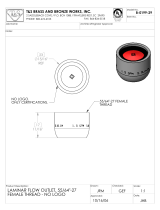 T & S Brass & Bronze Works B-0199-29 Datasheet
-
ACME RDM SPLITTER 18 User manual
-
Stairville DMX Splitter 6 RDM Quick start guide
-
Stairville DMX Splitter 6 RDM Quick start guide
-
Elation RDMS6 User manual
-
Botex 5P User guide
-
-
Sunricher SR-2100AMP-RDM-8CH-3 User manual
-
-
Stairville DMX Splitter 8 USB 5 pin User manual
