Page is loading ...

19" Widescreen Rack-Mount Console
with Built-In PRO3 KVM Switch
User Manual
8820-00768 Rev. A00 F1DC108H/F1DC116H

i
19” Widescreen Rack-Mount Console with Built-In PRO3 KVM Switch
SECTIONS 1 2 3 654 87Table of Contents
TABLE OF CONTENTS
1 Introduction . . . . . . . . . . . . . . . . . . . . . . . . . . . . . . . . . . . . . . . . . . . . .1
Package Contents ............................................ 2
2 Overview. ...............................................3
Feature Overview............................................. 3
Equipment Requirements ...................................... 4
System Requirements......................................... 5
Unit Display Diagrams......................................... 6
Specifications................................................ 7
3 Installation...............................................8
Pre-Configuration ............................................. 8
Connecting Servers to the Rack-Mount Console.................... 9
Connecting the Rack-Mount Console with Multiple
PRO3 KVM Switches (Daisy-Chaining) .......................... 13
Powering Up the Systems ................................... 17
4 Using your Rack-Mount Console ......................... 18
Selecting a Server or BANK Using Hot-Key Commands ........ 18
AutoScan Mode ............................................21
On-Screen Display (OSD) ................................... 21
Keyboard Hot-Key-Command Shortcuts ...................... 27
Sun Combo and Mac Key Mapping........................... 28
Updating Firmware .........................................29
5 Frequently Asked Questions. ............................30
6 Troubleshooting........................................32
7 Glossary ..............................................35
8 Information ............................................ 37

1
19” Widescreen Rack-Mount Console with Built-In PRO3 KVM Switch
SECTIONSTable of Contents 2 3 654 871
INTRODUCTION
Congratulations on your purchase of the Belkin 19-inch Widescreen
Rack-Mount Console with Built-In PRO3 KVM Switch (the Rack-Mount
Console). Our diverse line of KVM solutions exemplifies the Belkin
commitment to delivering high-quality, durable products at an
affordable price.
Designed to give you control over multiple servers, the Rack-Mount
Console provides an excellent solution for the server administrator.
It outperforms any other rack console with KVM switch on the market.
Engineered to work with the most advanced server room and laboratory
environments, this Rack-Mount Console offers:
• Single-railsystemwith1Ucompactdesign
• Videoresolutionsupportofupto1440x900
• PS/2andUSBsupportforinputdevices
• On-ScreenDisplay(OSD)
• Daisy-chaincapabilitywithotherBelkinPROswitches
(up to 256 servers)
• Security
• Flash-upgradeablefirmware
• Dual-portmicro-cabling(cablekitssoldseparately)
• Belkin2-YearWarranty
• Freetechnicalsupport
• 19-inchWidescreenLCD

2
19” Widescreen Rack-Mount Console with Built-In PRO3 KVM Switch
SECTIONSTable of Contents 2 3 654 871
INTRODUCTION
CD
1 Cable Kit*
DB9 -to -RJ11
Serial Flash Cable*
19” Widescreen
Rack-Mount Console
2 Brackets
1 Power Cord Quick Installation
Guide
Package Contents
This User Manual will provide details about your new Rack-Mount
Console, from installation and operation to troubleshooting—in the
unlikely event of a problem. For quick and easy installation, please refer
to the Quick Installation Guide included in your Rack-Mount Console
packaging.
Thank you for purchasing the Belkin Rack-Mount Console with Built-In
PRO3 KVM Switch. We appreciate your business and have confidence
that you will soon see for yourself why Belkin is the number-one-selling
brand in KVM switches worldwide.
*Models containing KVM switch only
or

3
19” Widescreen Rack-Mount Console with Built-In PRO3 KVM Switch
SECTIONSTable of Contents 1 3 654 87
OVERVIEW
2
Feature Overview:
Hot Keys
Hot-key functionality allows you to select a desired port using designated
key commands. By using a simple hot-key sequence on your keyboard,
you can select one server from as many as 256 servers, instantaneously.
AutoScan
The AutoScan feature allows you to set your Rack-Mount Console to
scan and monitor the activities of all connected servers, one by one.
The time interval allotted for each server can be adjusted through the
On-Screen Display (OSD) menu.
Video Resolution
The Rack-Mount Console supports video resolutions of up to 1440x900.
Security
Allows you to specify user names and passwords to prevent unauthorized
users from accessing the OSD and KVM Switch.
Dedicated Daisy-Chain Port
Up to 16 KVM switches can be daisy-chained together using dedicated
ports, so you can easily expand your KVM configuration as your server
environment grows.
On-Screen Display (OSD)
The OSD feature simplifies server management by allowing you to assign
individual names to each connected server throughout the system. It
provides a visual means of switching between servers and assigning
the hot-key scheme. The OSD can also be set up to support regional
languages.
Flash Upgrade
Flash-upgradeable firmware allows you to install the latest firmware on
your Rack-Mount Console. This enables your KVM Switch to maintain
consistent compatibility with the latest devices and servers. Firmware
upgrades are free for the life of your Rack-Mount Console and can be
downloaded from Belkin’s support website at www.belkin.com/support.

4
19” Widescreen Rack-Mount Console with Built-In PRO3 KVM Switch
SECTIONSTable of Contents 1 3 654 872
OVERVIEW
Equipment Requirements:
Cables:
Hot-key functionality allows you to select a desired port using designated
Connecting the Rack-Mount Console to a server requires a Belkin Dual-
Port Micro-Cable Kit.
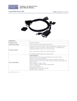
Belkin Dual-Port Micro-Cable Kits:
F1D9400-XX (PS/2-style)
F1D9401-XX (USB-style)
F1D9401-XX (USB-style)
F1D9400-XX (PS/2-style)

5
19” Widescreen Rack-Mount Console with Built-In PRO3 KVM Switch
SECTIONSTable of Contents 1 3 654 872
OVERVIEW
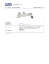
F1D108-CBL-XX
BelkinDaisy-ChainCable:F1D108-CBL-XX
(-XX denotes length in feet)
Note: Product codes and availability may vary.
System Requirements
OS Platforms
The Rack-Mount Console is compatible with CPUs running on, but not
limited to, the following OS platforms:
• Windows
®
NT
®
, 95, 98, 2000, Me, XP, Server 2003, or
Windows Vista
®
• Microsoft
®
DOS 5.x and above
• RedHat
®
Linux
®
8.x and above
• Novell
®
NetWare
®
5.x
• MacOS
®
X and above
• Sun
TM
Solaris
TM
8.x and above
Keyboards
• PS/2-compatible
• USB-compatible
• Supports101-/102-/104-keykeyboards
Mice
• PS/2-andUSB-compatiblemicehaving2,3,4,or5buttons
• PS/2-andUSB-compatiblewirelessoropticalmice

6
19” Widescreen Rack-Mount Console with Built-In PRO3 KVM Switch
SECTIONSTable of Contents 1 3 654 872
OVERVIEW
Unit Display Diagrams
Front View of the Widescreen Rack-Mount Console with Built-In
PRO3 KVM Switch:
Back View of the Widescreen Rack-Mount Console
with Built-In PRO3 KVM Switch:
105-Key
Keyboard
TFT/LCD
Active-Matrix
Color Panel
LCD Front-Panel
Controls
Touchpad
Handle
Console: VGA, PS/2 mouse/keyboard ports,
USB mouse/keyboard ports
Daisy-chain out
Flash-upgrade
port and DIP
select switch
SCSI-50 dual-host ports
DC power jack

7
19” Widescreen Rack-Mount Console with Built-In PRO3 KVM Switch
SECTIONSTable of Contents 1 3 654 872
OVERVIEW
Specifications
Part No.: F1DC108H, F1DC116H
Daisy-Chain: Maximum of 16 OmniView KVM Switches
No. of Servers Supported:
8 and 16 respectively for 8- and 16-port
models (256 servers max. via daisy-chaining)
Keyboard Input:
PS/2 (miniDIN6), USB (Type A)
Mouse Input:
PS/2 (miniDIN6), USB (Type A)
Monitor Port: VGA (HDDB15 female)
CPU Ports: S C S I - 5 0
Daisy-Chain Ports: DB25 female
Flash-Upgrade Port: RJ11
Operating Temp: 32° to 104° F (0~40° C)
Storage Temp: -4° to 140° F (20~60° C)
Humidity: 0-80% RH, non-condensing
Warranty: 2 years
Note: Specifications are subject to change without notice.

8
19” Widescreen Rack-Mount Console with Built-In PRO3 KVM Switch
SECTIONSTable of Contents 1 2 654 87
INSTALLATION
3
For USB Servers:
USB signals can be transmitted up to 15 feet (4.5m) between the Rack-
Mount Console and server. Beyond that length, the probability of USB-
signal failure is likely, and may cause the device to fail.
Note: The Belkin OmniView CAT5 Extender, F1D084 (PS/2) and F1D086U
(USB), may be used to extend your console (keyboard, mouse, and
monitor) by up to 300 feet (91m).
Cautions and Warnings!
Avoid placing cables near fluorescent lights, air-conditioning equipment,
or machines that create electrical noise (e.g., vacuum cleaners).
Before attempting to connect anything to the Rack-Mount Console or your
servers, ensure that everything is powered off. Plugging and unplugging
cables while servers are powered on may cause irreversible damage of
the servers and/or the Rack-Mount Console. Belkin is not responsible for
damage caused in this way.
You are now ready to begin installation of your Rack-Mount
Console. The following sections (pages 9–17) provide complete
instructions for the hardware setup of a single Rack-Mount Console
(F1DC108B-SR, F1DC116B-SR).
Pre-Configuration
Consider the following when deciding where to place the
Rack-Mount Console with Built-In PRO3 KVM Switch:
• thelocationofyourserversinrelationtoyourconsole
• thelengthsofthecablesyouusetoconnectyourserverstothe
Rack-Mount Console
Cable-Distance Requirements:
For PS/2 Servers:
VGA signals transmit best up to 25 feet (7.6m). Beyond that length,
the probability of video degradation increases. For this reason, Belkin
recommends that the length of the cables between the Rack-Mount
Console and the connected servers does not exceed 25 feet (7.6m).

9
19” Widescreen Rack-Mount Console with Built-In PRO3 KVM Switch
SECTIONSTable of Contents 1 2 654 873
INSTALLATION
Connecting Servers to the Rack-Mount Console
(PS/2 Connection):
Step 1
Make sure your server is powered off.
Step 2
Using the Belkin Dual-Port Micro-Cable Kit for PS/2 (F1D9400-XX),
connect the VGA connector to the monitor port on your server. (Refer to
diagram on the right.)
Step 3
Connect the PS/2 mouse and keyboard connectors to the mouse and
keyboard ports on the server. (Refer to diagram on the right.)

10
19” Widescreen Rack-Mount Console with Built-In PRO3 KVM Switch
SECTIONSTable of Contents 1 2 654 873
INSTALLATION
Step 4
Connect the Belkin Dual-Port Micro-Cable Kit for PS/2 to the desired host
ports on the PRO3 KVM Switch. (Refer to diagram on the right.)
Step 5
Power up your server.
Step 6
Repeat Steps 1 through 5 for each additional PS/2 server you wish
to connect.

11
19” Widescreen Rack-Mount Console with Built-In PRO3 KVM Switch
SECTIONSTable of Contents 1 2 654 873
INSTALLATION
Connecting Servers to the Rack-Mount
Console (USB Connection):
Step 1
Make sure your server is powered off.
Step 2
Using the Belkin Dual-Port Micro-Cable Kit for USB (F1D9401-XX),
connect the VGA connector to the monitor port on your server. (Refer to
diagram on the right.)
Step 3
Connect the USB connector to an available USB port on the server.
(Refer to diagram on the right.)

12
19” Widescreen Rack-Mount Console with Built-In PRO3 KVM Switch
SECTIONSTable of Contents 1 2 654 873
INSTALLATION
Step 4
Connect the Belkin Dual-Port Micro-Cable Kit for USB to the desired host
portsonthePRO3KVMSwitch.(Refertodiagramontheleft.)Yourserver
should recognize the KVM-Switch connection and automatically install the
HID USB driver, if necessary.
Step 5
Note: We recommend that you attach the Belkin Dual-Port Micro-Cable
USB Kit directly to a free USB port on your server.
Note: When a USB Cable Kit is connected to a Sun server, the Server
Interface Module emulates the Sun keys using a set of key combinations
called “combo keys”. Refer to the table on page 28 for a list of Sun
functions supported by the Rack-Mount Console.

13
19” Widescreen Rack-Mount Console with Built-In PRO3 KVM Switch
SECTIONSTable of Contents 1 2 654 873
INSTALLATION
Connecting the Rack-Mount Console with Multiple
PRO3 KVM Switches (Daisy-Chaining)
Youcandaisy-chainupto15additionalPRO3KVMSwitches(F1DA104Z,
F1DA108Z,F1DA116Z,F1DA104Q,F1DA108Q,andF1DA116Q),allowing
a server administrator to manage up to a maximum of 256 servers from
one console. Each daisy-chained PRO3 KVM Switch is referred to as a
“BANK” and is assigned an address. The Rack-Mount Console is BANK
00 and is referred to as the “primary” KVM switch. BANKs 01 through 15
are referred to as “secondary” KVM switches.
Note: The Rack-Mount Console (F1DC108B-SR, F1DC116B-SR) must be
designated as the primary KVM switch. Refer to the diagram on the right.
Note:ADaisy-ChainCable(F1D108-CBL)isrequiredtodaisy-chaineach
PRO3 KVM Switch and is available through your Belkin reseller, or online
at www.belkin.com.
cable 1
cable 2
cable 3
Primary unit (BANK 00)
Secondary unit (
BANK 01)
Secondary unit (
BANK 02)
Secondary unit (
BANK 03)

14
19” Widescreen Rack-Mount Console with Built-In PRO3 KVM Switch
SECTIONSTable of Contents 1 2 654 873
INSTALLATION
DIP SWITCH# BANK
ADDRESS
1 2 3 4 5 6
ON ON ON ON ON ON BANK 0 PRIMARY(default)
ON ON OFF ON ON ON BANK 1 SECONDARY
ON ON ON OFF ON ON BANK 2 SECONDARY
ON ON OFF OFF ON ON BANK 3 SECONDARY
ON ON ON ON OFF ON BANK 4 SECONDARY
ON ON OFF ON OFF ON BANK 5 SECONDARY
ON ON ON OFF OFF ON BANK 6 SECONDARY
ON ON OFF OFF OFF ON BANK 7 SECONDARY
ON ON ON ON ON OFF BANK 8 SECONDARY
ON ON OFF ON ON OFF BANK 9 SECONDARY
ON ON ON OFF ON OFF BANK 10 SECONDARY
ON ON OFF OFF ON OFF BANK 11 SECONDARY
ON ON ON ON OFF OFF BANK 12 SECONDARY
ON ON OFF ON OFF OFF BANK 13 SECONDARY
ON ON ON OFF OFF OFF BANK 14 SECONDARY
ON ON OFF OFF OFF OFF BANK 15 SECONDARY
ON = Up Position, OFF = Down Position
How to Assign a BANK Address
All PRO3 KVM Switches feature a “BANK DIP” switch. The “BANK DIP”
switch is used to assign the proper BANK address to each PRO3
KVM Switch.
For a multi-unit configuration, the primary KVM switch (Rack-Mount
Console) is always set to “BANK address 00”. Each secondary unit must
be set to a unique BANK address (from 01 through 15). Refer to the chart
on the right for “BANK DIP” switch settings.
Example: Three8-PortPRO3KVMSwitches(F1DA108Z)aredaisy-
chained together with a Rack-Mount Console to manage up to 32 servers.
The DIP switch on the primary KVM (Rack-Mount Console) switch is set
to “BANK 00” (factory default) and the secondary units are each set to a
unique BANK (between 01 and 03).

15
19” Widescreen Rack-Mount Console with Built-In PRO3 KVM Switch
SECTIONSTable of Contents 1 2 654 873
INSTALLATION
Example of Daisy-Chain Configuration
Getting Started
Step 1: Make sure that all servers, Rack-Mount Console, and PRO3 KVM
Switches are powered off and that each PRO3 KVM Switch has been
assigned a unique BANK address.
Step 2: Place all primary and secondary KVM switches in the
desired location.
cable 1
cable 2
cable 3
Primary unit (BANK 00)
Secondary unit (
BANK 01)
Secondary unit (
BANK 02)
Secondary unit (
BANK 03)

16
19” Widescreen Rack-Mount Console with Built-In PRO3 KVM Switch
SECTIONSTable of Contents 1 2 654 873
INSTALLATION
Connecting the Primary and Secondary KVM Switches:
Step 1
UsingtheDaisy-ChainCable(F1D108-CBL),connectoneendtothe
“Daisy-Chain In” port on the Rack-Mount Console (BANK 00).
Step 2
ConnecttheotherendoftheDaisy-ChainCable(F1D108-CBL)tothe
“Daisy-Chain Out” port of the first secondary KVM switch (BANK 01).
Step 3
To add secondary units, connect one end of the Daisy-Chain Cable
(F1D108-CBL)tothe“Daisy-ChainIn”portonthefirstsecondaryKVM
switch and the other end to the “Daisy-Chain Out” port of the next
secondary KVM switch (for example, BANK 01).
Step 4
Repeat Step 3 for additional PRO3 KVM Switches you wish to
daisy-chain together.
Connecting the Servers:
Step 1:
Connect all servers to the primary and secondary KVM switches. Refer to
the “Connecting Servers to the Rack-Mount Console” section on page 9
for instructions.
Step 2:
Power up the secondary KVM switches sequentially, beginning with the
highest BANK, by connecting each unit’s power supply. Each KVM switch
should display its corresponding BANK-address number as it is powered up.
Step 3:
Verify that the primary KVM switch has detected all secondary KVM
switches by scrolling through the BANKs by using the OSD.

17
19” Widescreen Rack-Mount Console with Built-In PRO3 KVM Switch
SECTIONSTable of Contents 1 2 654 873
INSTALLATION
Powering Up the Systems
Verify that all servers connected to the PRO3 KVM Switch are powered
on. If any connected servers have not been powered on, it is okay to do so
at this time (servers can be powered on simultaneously). The PRO3 KVM
Switch emulates both a mouse and keyboard on each port and allows
your server to boot normally.
The server connected to Port “1” will be displayed on the monitor. Check
that the keyboard, monitor, and mouse are working normally. Check all
occupied ports to verify that all servers are connected and responding
correctly. If you encounter an error, check your cable connections
for that server and reboot. If the problem persists, please refer to the
“Troubleshooting” section in this User Manual.

18
19” Widescreen Rack-Mount Console with Built-In PRO3 KVM Switch
SECTIONSTable of Contents 1 2 3 5 874
Using YoUr rack-MoUnt console
6
Now that you have connected your console and servers to your Rack-
Mount Console, it is ready for use. Select connected servers through the
On-Screen Display; or by using hot-key commands through the console
keyboard. It takes approximately 1–2 seconds for the video signal to
refresh after switching servers. Re-synchronization of the mouse and
keyboard signals also occurs. This is normal operation and ensures
that proper synchronization is established between the console and the
connected servers.
Selecting a Server or BANK Using Hot-Key Commands
Switch to the next or previous port with simple, keyboard hot-key
sequencesusingthe“ScrollLock”key,andeitherthe“Up”or“Down”
arrowkeys.TosendcommandstotheKVMSwitch,the“ScrollLock”key
must be pressed twice within two seconds. The Rack-Mount Console will
beep, confirming that it is in hot-key mode. Next, press the “Up” arrow
key and the PRO3 KVM Switch will switch to the previous port. Press the
“Down” arrow key to switch to the next port.
Switch to next active port,
“Down” arrow
Switch to previous active port, “Up” arrow.
/