Page is loading ...

Date Issued: 04/04/17 IS-45685-US
We’re here to help 866-558-5706
Hrs: M-F 9am to 5pm EST
CAUTION – RISK OF SHOCK –
Disconnect power at the main circuit breaker panel or main fuse
box before starting and during the installation.
WARNING:
This fixture is intended for installation in accordance with the
National Electrical Code (NEC) and all local code specifications.
If you are not familiar with code requirements, installation by
a certified electrician is recommended.
CLEANING:
Always be certain that electric current is turned off before clean
ing. Only a damp cloth should be used. Harsh cleaning products
may damage the finish.
FCC INFORMATION:
This device complies with part 15 of the FCC Rules. Operation is
subject to the following two conditions:
(1) This device may not cause harmful interference, and
(2) this device must accept any interference received, including
interference that may cause undesired operation.
Note: This equipment has been tested and found to comply
with the limits for a Class B digital device, pursuant to part
15 of the FCC Rules. These limits are designed to provide
reasonable protection against harmful interference in a resi-
dential installation. This equipment generates, uses and can
radiate radio frequency energy and, if not installed and used
in accordance with the instructions, may cause harmful
interference to radio communications. However, there is no
guarantee that interference will not occur in a particular in-
stallation. If this equipment does cause harmful interference
to radio or television reception, which can be determined by
turning the equipment off and on, the user is encouraged to
try to correct the interference by one or more of the follow-
ing measures:
• Reorient or relocate the receiving antenna.
• Increase the separation between the equipment and re-
ceiver.
• Connect the equipment into an outlet on a circuit different
from that to which the receiver is connected.
• Consult the dealer or an experienced radio/TV technician for
help.
INSTALLATION:
• Read and understand all instructions and illustrations com-
pletely before proceeding with assembly and installation of
fixture.
• If you have any doubts about how to install this fixture, or
if the fixture fails to operate completely, please contact a
qualified electrician.
• All parts must be used as indicated in the instructions. Do
not substitute any parts, leave parts out, or use any parts
that are worn or broken. Failure to obey this instruction
could invalidate the UL listing, C.S.A. certification, and/or
ETL listing of this fixture.
• Fixture is to be connected to a single branch circuit.
• Mounting surface should be clean, dry, flat and 1/4” larger
than the fixture housing surface.
INSTRUCTIONS:
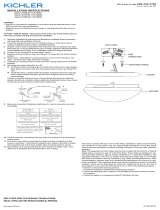
1) Remove (2) Mounting Screws.
2) Slide mounting plate out of canopy.
3) Attach the mounting plate to the outlet box with supplied
screws. NOTE: The mounting strap must be mounted with
the fixture threaded holes on top and bottom.
4) Grounding instructions: (See Illus. A or B)
i. On fixtures where mounting strap is provided with a hole
and two raise dimples. Wrap ground wire from outlet box
around green ground screw, and thread into hole.
ii. On fixtures where a cupped washer is provided. Put ground
wire from outlet box under cupped washer and green
ground screw and thread screw into hole in mounting strap.
If fixture is provided with ground wire. Connect fixture
ground wire to outlet box ground wire with wire connector,
after following the above steps. Never connect ground wire
to black or white power supply wires.
GREEN GROUND
SCREW
CUPPED
WASHER
OUTLET BOX
GROUND
FIXTURE
GROUND
DIMPLES
WIRE CONNECTOR
OUTLET BOX
GROUND
GREEN GROUND
SCREW
FIXTURE
GROUND
A
B
5) Make wire connections. Reference chart below for correct
connections and wire accordingly.
6) Place fixture up to mounting plate. Carefully push wire con-
nections inside mounting plate and canopy making sure all
connections remain secure and wires do not get pinched.
7) Insert and tighten mounting screws to secure Fixture to wall.
CLEANING GLASS INSTRUCTION:
1) Turn end cap counter-clockwise to remove. Set aside.
2) Remove screws and plate and set aside.
3) Slide glass out of fixture taking care not to touch LED mod-
ule.
4) Only a damp cloth should be used to clean glass. Harsh
cleaning products may damage the finish.
5) Assembly in reverse order.
6) Repeat steps 1-5 for opposite side.
Connect Black or
Red Supply Wire to:
Connect
White Supply Wire to:
Black White
*Parallel cord (round & smooth) *Parallel cord (square & ridged)
Clear, Brown, Gold or Black
without tracer
Clear, Brown, Gold or Black
with tracer
Insulated wire (other than green)
with copper conductor
Insulated wire (other than green)
with silver conductor
*Note: When parallel wires (SPT I & SPT II)
are used. The neutral wire is square shaped
or ridged and the other wire will be round in
shape or smooth (see illus.)
Neutral Wire
(2) GLASS
LED MODULE
MOUNTING PLATE
(2) MOUNTING SCREWS
CANOPY
SCREWS
PLATE
COVER
END CAP
(2) MOUNTING PLATE SCREWS
WIRE CONNECTORS
SEE OTHER SIDE FOR SPANISH TRANSLATIONS.
VEA EL OTRO LADO DE TRADUCCIONES AL ESPAÑOL.

Date Issued: 04/04/17 IS-45685-US
We’re here to help 866-558-5706
Hrs: M-F 9am to 5pm EST
PRECAUCIÓN – RIESGO DE DESCARGA ELÉCTRICA –
Desconecte la electricidad en el panel principal del interruptor
automático o caja principal de fusibles antes de comenzar y
durante la instalación.
ADVERTENCIA:
Este artefacto está diseñado para instalarse de acuerdo con el
Código Nacional de Electricidad (NEC, por sus siglas en inglés)
y todas las especificaciones de códigos locales. Si usted no
está familiarizado con los requisitos del código, se recomienda
la instalación por un electricista certificado.
LIMPIEZA:
Asegúrese siempre que la corriente eléctrica esté apagada antes
de limpiar. Se debe usar solo un paño húmedo. Productos de
limpieza abrasivos pueden dañar el acabado.
INFORMACIÓN DE LA FCC:
Este artefacto cumple con la parte 15 de las Normas de la FCC.
El funcionamiento está sujeto a las siguientes dos condiciones:
(1) Este artefacto no puede causar interferencia perjudicial, y
(2) este artefacto debe aceptar cualquier interferencia recibida,
inclusive interferencia que puede causar una operación no
deseada.
Nota: Este equipo ha sido probado y se comprobó que
cumple con los límites para un artefacto digital Clase B, de
conformidad con la parte 15 de las Normas de la FCC. Estos
límites están diseñados para proporcionar una protección
razonable contra interferencia perjudicial en una instalación
residencial. Este equipo genera, usa y puede radiar energía
de radio frecuencia y, si no se instala y usa de acuerdo con
las instrucciones, puede causar interferencia perjudicial a
las comunicaciones de radio. Sin embargo, no hay garantía
de que la interferencia no ocurrirá en una instalación en par-
ticular. Si este equipo sí causa interferencia perjudicial a la
recepción de radio o televisión, que puede ser determinado
encendiendo y apagando el equipo, se aconseja al usuario
que trate de corregir la interferencia con una o más de las
siguientes medidas:
• Reoriente o cambie de lugar la antena de recepción.
• Aumente la separación entre el equipo y el receptor.
• Conecte el equipo en un receptáculo en un circuito diferente
de donde está conectado el receptor.
• Consulte al concesionario o a un técnico experimentado de
radio/TV para que le ayude.
INSTALACIÓN:
• Lea y entienda completamente todas las instrucciones e
ilustraciones antes de proceder con el ensamblaje e insta-
lación del artefacto.
• Si tiene alguna duda sobre cómo instalar este artefacto, o si
el artefacto no opera completamente, contacte a un electri-
cista calificado.
• Todas las partes deben ser usadas como se indica en las
instrucciones. No sustituya partes, deje partes afuera o use
partes que estén gastadas o rotas. El no obedecer estas
instrucciones podría invalidar la clasificación UL, la certifi-
cación de C.S.A. y/o la clasificación ETL de este artefacto.
• El artefacto tiene que conectarse a un circuito de un solo
ramal.
• La superficie de montaje debe estar limpia, seca y plana, y
ser ¼ de pulgada más grande que la superficie de la cubi-
erta del artefacto.
INSTRUCCIONES:
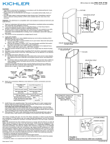
1) Remueva (4) Tornillos de Montaje.
2) Deslice la placa de montaje fuera del escudete.
3) Fije la placa de montaje a la caja de salida con los tornil-
los provistos. NOTA: La abrazadera de montaje debe ser
montada con los agujeros roscados en la parte superior e
inferior.
4) Instrucciones para poner a tierra: (Ver Ilustraciones A o B)
i. En artefactos donde se suministra la abrazadera de montaje
con un agujero y dos depresiones onduladas, envuelva el
conductor de tierra de la caja de salida alrededor del tornillo
de conexión a tierra verde y atorníllelo en el agujero.
ii. En los artefactos provistos de arandela cóncava, pase el
conductor de tierra desde la caja de salida entre la arandela
cóncava y el tornillo de conexión a tierra verde, y atorníllelo
en la abrazadera de montaje.
Si se suministra el artefacto con conductor de tierra, co-
necte el conductor de tierra del artefacto al conductor de
tierra de la caja de salida con conector de cable después
de seguir los pasos anteriores. Nunca conecte el conduc-
tor de tierra a los cables de alimentación eléctrica negros o
blancos.
ARANDELA
CONCAVA
TIERRA DE LA
CAJA DE SALIDA
TORNILLO DE TIERRA,
VERDE
DEPRESIONES
TIERRA
ARTEFACTO
CONECTOR DE ALAMBRE
TIERRA DE LA
CAJA DE SALIDA
TORNILLO DE TIERRA,
VERDE
TIERRA
ARTEFACTO
A
B
5) Haga las conexiones de cables. Consulte la gráfica de
abajo con las conexiones correctas y haga el cableado que
corresponda.
6) Coloque el artefacto hasta la placa de montaje. Empuje cui-
dadosamente las conexiones de cables dentro de la placa
de montaje y del escudete asegurando que todas las conex-
iones permanecen firmes y los cables no queden apretados.
7) Inserte y apriete los tornillos de montaje para asegurar el
artefacto a la pared.
INSTRUCCIÓN PARA LIMPIAR EL VIDRIO:
1) Gire la tapa del extremo hacia la izquierda para removerla.
Apártela.
2) Remueva los tornillos y la placa y apártelos.
3) Deslice el vidrio fuera del artefacto teniendo cuidado de no
tocar el módulo LED.
4) Se debe usar solo un paño húmedo. Productos de limpieza
abrasivos pueden dañar el acabado.
5) Ensamble en orden inverso.
6) Repita los pasos 1-5 para el lado opuesto.
Conectar el alambre de
suministro negro o rojo al
Conectar el alambre de
suministro blanco al
Negro Blanco
*Cordon paralelo (redondo y liso)
*Cordon paralelo (cuadrado y estriado)
Claro, marrón, amarillio o negro
sin hebra identificadora
Claro, marrón, amarillio o negro
con hebra identificadora
Alambre aislado (diferente del verde)
con conductor de cobre
Alambre aislado (diferente del
verde) con conductor de plata
*Nota: Cuando se utiliza alambre paralelo
(SPT I y SPT II). El alambre neutro es de forma
cuadrada o estriada y el otro alambre será de
forma redonda o lisa. (Vea la ilustracíón).
Hilo Neutral
(2) VIDRIO
MÓDULO LED
PLACA DE MONTAGE
(2) TORNILLO DE MONTAJE
ESCUDETE
EMPULGUERAS
PLACA
CUBIERTA
TAPA
(2) EMPULGUERAS
CONECTORES DE ALAMBRE
SEE OTHER SIDE FOR ENGLISH TRANSLATIONS.
VEA EL OTRO LADO DE TRADUCCIONES AL INGLÉS.
/


