6 KBD Series Manual
Consideraon of care for your water heater should
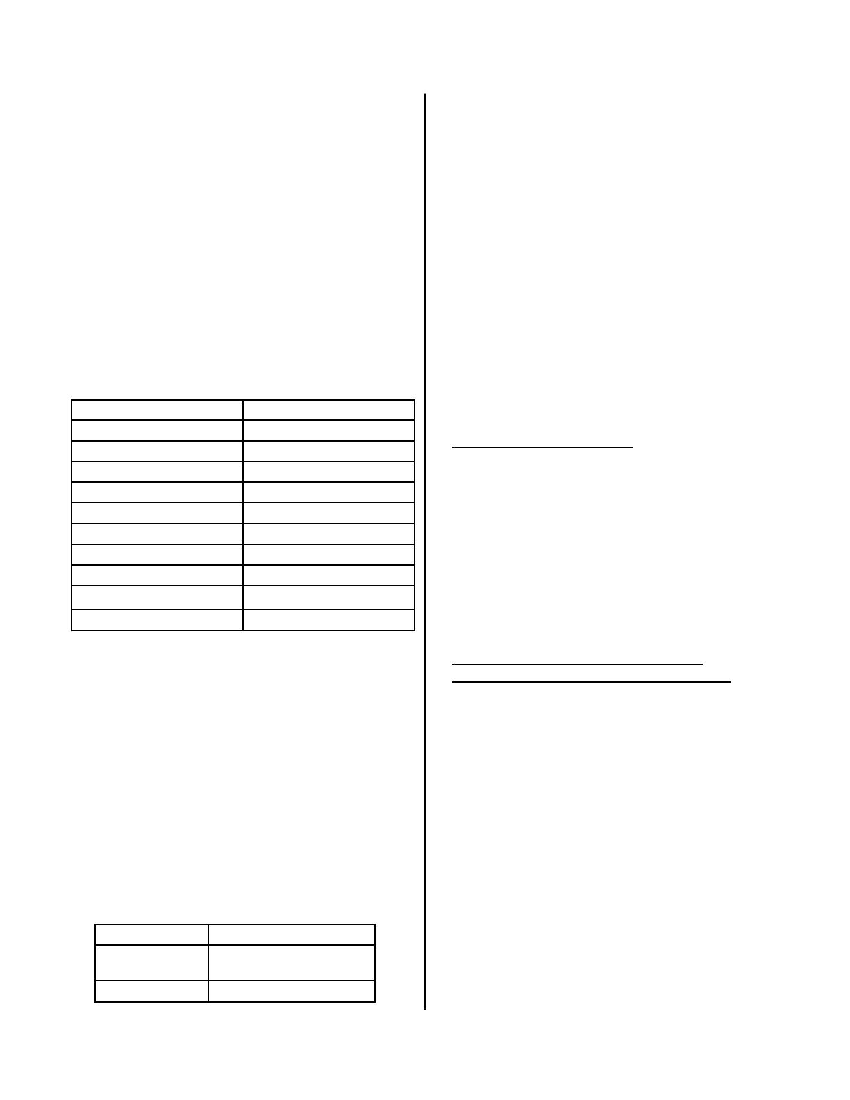
include evaluaon of water quality.
Total Hardness Up to 200 mg / L
Aluminum * Up to 0.2 mg / L
Chlorides * Up to 250 mg / L
Copper * Up to 1.0 mg / L
Dissolved Carbon Dioxide (CO2) Up to 15.0 mg / L or PPM
Iron * Up to 0.3 mg / L
Manganese * Up to 0.05 mg / L
pH * 6.5 to 8.5
TDS (Total Dissolved Solids) * Up to 500 mg / L
Zinc * Up to 5 mg / L
Environment
Air surrounding the water heater, venng, and vent
terminaon(s) is used for combuson and must be free
of any compounds that cause corrosion of internal
components. These include corrosive compounds that
are found in aerosol sprays, detergents, bleaches,
cleaning solvents, oil based paints/ varnishes, and
refrigerants. The air in beauty shops, dry cleaning
stores, photo processing labs, and storage areas for pool
supplies oen contains these compounds. Therefore it
is recommended that outdoor models be used for these
locaons where possible.
The water heater, venng, and vent terminaon(s)
should not be installed in any areas where the air may
contain these corrosive compounds. If it is necessary for
a water heater to be located in areas that may contain
corrosive compounds, the following instrucons are
strongly recommended.
Indoor/Internal Water Heaters
DO NOT Install in areas where air for combuson
might be contaminated with chemicals.
Before installaon, consider where air has the
ability to travel within the building to the water
heater.
Where possible, install the water heater in a sealed
closet so that it is protected from the potenal of
contaminated indoor air.
Chemicals that are corrosive in nature should not
be stored or used near the water heater.
Outdoor/External Water Heaters and Vent
Terminaons of Indoor/Internal Water Heaters
Install the water heater as far away as possible
from exhaust vent hoods.
Install as far away as possible from any air inlet
vents. Corrosive fumes may be released through
these vents when air is not being brought in
through them.
Chemicals that are corrosive in nature should not
be stored or used near the water heater or vent
terminaon.
Damage and repair due to corrosive compounds in the
air is not covered by warranty.
Water Quality
* Source: Part 143 Naonal Secondary Drinking Water Regulaons
If you install this water heater in an area that is known
to have hard water or that causes scale build-up
the water must be treated and may require more
frequent heat exchanger ushing schedule.
When scale build-up in the heat exchanger begins to
aect the performance of the water heater, a diagnosc
code “LC#” will display. Flush the heat exchanger to
prevent damage to it. Scale build up is caused by hard
water and can be accelerated if the unit is set at a high
temperature.
Rinnai oers Southeastern Filtraon’s “ScaleCuer
Water Condioning System” that oers superior lime
scale prevenon and corrosion control by feeding a
blend of control compounds into the cold water supply.
You must ensure that clearances will be met and that
the vent length will be within required limits. Consider
the installaon environment, water quality, and need
for freeze protecon. Requirements for the gas line,
water lines, electrical connecon, and condensate
disposal can be found in their respecve installaon
secons of this manual.
Part Number Descripon
103000038
Southeastern Filtratrion
ScaleCuer System 3/4” Feed
103000039
ScaleCuer Rell


