Page is loading ...

1
5
9
3
7
11
2
6
10
4
8
12
13
14
Owner’s Manual
PROTECT
YOUR INVESTMENT!
Completed and signed start-up
forms MUST be submitted and approved
by Tripp Lite to activate your warranty.
1
SmartOnline
™
3-Phase UPS Systems
Models: SU20KX, SU40KX, SU60KX, SU80KX
Input/Output: 220/380V, 230/400V or 240/415V AC, 3
ϕ
, 4-wire + PE
Not suitable for mobile applications.
1111 W. 35th Street, Chicago, IL 60609 USA • www.tripplite.com/support
Copyright © 2013 Tripp Lite. All trademarks are the sole property of their respective owners.

1
5
9
3
7
11
2
6
10
4
8
12
13
14
2
Table of Contents
1 Introduction 3
2 Important Safety Instructions 4
3 Control Panel Features 6
4 Front and Rear Panel Features 7
5 Cabinet Installation 9
5-1 Preparation 9
5-2 Unpacking 9
5-3 Placement 10
6 Internal Battery Connection 11
(Models SU20KX and SU40KX Only)
6-1 Internal Battery Wiring Diagrams 11
6-2 Internal Battery Connection Procedure 13
7 Wiring 16
7-1 Wiring Warnings 16
7-2 Wiring Preparation 16
7-3 UPS System Terminal Block Diagram 17
7-4 External Battery Cabinet Wiring Diagrams 17
7-5 Electrical and Cable Data 18
7-6 External Battery Cabinet Wiring 19
7-7 AC Input/Output Wiring (Single UPS) 20
7-8 AC Input/Output Wiring (Parallel UPS – Single Input) 21
7-9 AC Input/Output Wiring (Parallel UPS – Dual Inputs) 21
8 Operating Modes 22
8-1 Online (Normal) Mode (Single UPS) 22
8-2 Battery Backup Mode (Single UPS) 22
8-3 Auto Bypass Mode (Single UPS) 22
8-4 Manual Bypass Mode (Single UPS) 22
8-5 Online Mode (Parallel UPS) 23
8-6 Battery Backup Mode (Parallel UPS) 23
8-7 Auto Bypass Mode (Parallel UPS) 23
8-8 Manual Bypass Mode (Parallel UPS) 24
8-9 Hot Standby Mode (Parallel UPS) 24
9 Start-Up, Shutdown and Bypass 25
9-1 Control Panel and Breaker Diagrams 25
9-2 Preliminary Checklist (Single UPS) 25
9-3 Normal Start-Up Procedure (Single UPS) 25
9-4 Battery Start-Up Procedure (Single UPS) 26
9-5 Manual Bypass Procedure (Single UPS) 27
9-6 Shutdown Procedure (Single UPS) 27
9-7 Preliminary Checklist (Parallel UPS) 28
9-8 Start-Up Procedure (Parallel UPS) 29
9-9 Shutdown Procedure (Parallel UPS) 30
9-10 Manual Bypass Procedure (Parallel UPS) 31
9-11 Switching from Manual Bypass to Normal (Parallel UPS) 32
10 Display and Configuration 33
10-1 Control Panel Diagram 33
10-2 Display Hierarchy 33
10-3 Default Display 34
10-3-1 Status Display 34
10-4 Main Menu 37
10-5 UPS Setup 39
10-5-1 Bypass Setup 40
10-5-2 Output Setup 41
10-5-3 Battery Setup 43
10-5-4 Charger Setup 46
10-5-5 Parallel Setup 47
10-5-6 Control & Test Setup 48
10-5-7 Local Setup 50
10-6 Maintenance 53
11 Communications 55
11-1 Communications Interfaces 55
11-2 SNMPWEBCARD Slot 55
11-3 Input Dry Contact Interface 55
11-4 Remote Emergency Power Off (EPO) Circuit Diagram 56
11-5 Auxiliary Dry Contact Input Circuit Diagram 56
11-6 External Battery Cabinet Temperature Inputs 56
11-7 External Battery Status Input 56
11-8 Output Dry Contact Interface Detail 57
11-9 Output Dry Contact Circuit Diagram 58
11-10 RS-232 Serial Port Circuit Diagram 58
11-11 Parallel Conguration Port 58
12 Specifications 59
12-1 UPS System Technical Specications 59
12-2 UPS System Floor Loading Table 59
12-3 Battery Pack Floor Loading Table 59
13 Storage and Service 60
14 Warranty 60
Español 61
Français 121
181

1
5
9
3
7
11
2
6
10
4
8
12
13
14
3
1 – Introduction
Tripp Lite’s SmartOnline 3-Phase UPS Systems (Models SU20KX, SU40KX, SU60KX and SU80KX) are ideal for backing up and protecting data
centers, telecommunications (VoIP), networks, industrial facilities, security/emergency systems and more.
Advanced Features:
• True on-line double conversion with superior IGBT inverter technology
• Low input current THD allows 1:1 generator sizing for maximum efficiency and cost savings
• Internal N+1 power module redundancy (SU40KX, SU60KX and SU80KX)
• Built-in parallel or hot standby redundancy (1+1) capability for increased capacity or fault-tolerance
• Up to 80kVA capacity in a compact footprint; up to 160kVA in parallel configuration
• High input power factor and high efficiency with low thermal loss and low noise
• Simplified, easy-to-repair, long-life, high-availability system design
• Redundant auxiliary power and control circuits
• Dual input design with separated rectifier and bypass input
• All models support external battery cabinets for extended battery backup runtime
• High-resolution LCD status screen simplifies operation and delivers detailed operational information, including system block diagrams

1
5
9
3
7
11
2
6
10
4
8
12
13
14
4
2 – Important Safety Instructions
SAVE THESE INSTRUCTIONS
All sections of this manual contains instructions and warnings that should be followed during the installation and operation of the UPS
systems described in this manual. Read all instructions thoroughly before attempting to move, install or operate the UPS systems described in
this manual. Failure to comply may invalidate the warranty and cause property damage and/or personal injury.
Location Warnings
• Install the UPS system in a controlled indoor environment, away from moisture, temperature extremes, flammable liquids and gasses, conductive
contaminants, dust and direct sunlight.
• Install the UPS system in a level, structurally sound location.
• The UPS system is extremely heavy; be extremely careful when moving or lifting the unit.
• Operate the UPS system at indoor temperatures between 32° F and 104° F (0° C and 40° C) only. For best results, maintain indoor temperatures
between 62° F and 84° F (17° C and 29° C).
• Leave adequate space around all sides of the UPS system for proper ventilation. Do not block, cover or insert objects into the external ventilation
openings of the cabinet.
• Do not place any object on the unit, especially containers of liquid.
• Do not mount the unit with its front or rear panel facing down (at any angle). Mounting in this manner will seriously inhibit the unit’s internal
cooling, eventually causing product damage not covered under warranty.
• Do not install the UPS system near magnetic storage media, as this may result in data corruption. Keep all recorded magnetic media a minimum
of 60 cm (24 inches) away from the UPS system.
• Do not attempt to stack the UPS system. Attempting to stack the UPS system may cause permanent damage and create a potential for serious
personal injury.
• The casters are designed for minor position adjustments within the final installation area only. The casters are not designed for moving the UPS
system over longer distances.
• The casters are not designed to provide long-term support for the UPS system after final installation. Use the levelers to provide long-term
support.
• When moving the UPS system, push from the front or rear, not from the sides.
• Do not attempt to unpack or move the UPS system without assistance.
Connection Warnings
• ThepowersupplyfortheUPSsystemmustbe3-phaseratedinaccordancewiththeequipmentnameplate.Italsomustbesuitably
groundedandwiredaccordingtoallapplicablenationalandlocalelectricalwiringstandards,codesandregulations.
• The UPS system contains hazardous high voltages that have the potential to cause personal injury or death from electric shock.
• The UPS system has its own energy source (battery – internal and/or external). The output terminals may be live even when the UPS system is
not connected to an AC supply.
• If the UPS system receives power from a motor-powered AC generator, the generator must provide clean, filtered, computer-grade output.
• Use of this equipment in life support applications where failure of this equipment can reasonably be expected to cause the failure of the life
support equipment or to significantly affect its safety or effectiveness is not recommended. Do not use this equipment in the presence of a
flammable anesthetic mixture with air, oxygen or nitrous oxide.
• The UPS system is designed to power modern computer loads and associated peripheral devices. Do not use the UPS system to power pure
inductive or capacitive loads.
• Input and output wiring should be performed by trained, qualified electricians only.
• Due to high leakage current, a proper earth ground connection is essential before connecting the AC supply.
• Isolate the UPS system before working on the circuit. An easily accessible disconnect device should be incorporated in the fixed wiring. The
disconnect device must disconnect all line conductors simultaneously when opened.

1
5
9
3
7
11
2
6
10
4
8
12
13
14
5
2 – Important Safety Instructions
Battery Warnings
• The UPS system does not require routine maintenance. There are no user-serviceable parts inside. Only qualified service personnel should open
the access panels for any reason.
• Batteries present a risk of electrical shock and burns from high short-circuit current. Battery connection or replacement should be performed
only by qualified service personnel, observing proper precautions. Turn off the UPS system before connecting or disconnecting internal
batteries. Use tools with insulated handles. Do not open the batteries. Do not short or bridge the battery terminals with any object.
• Replace batteries with equivalent batteries available from Tripp Lite. Do not operate the UPS system without batteries.
• The batteries are recyclable. Refer to local codes for disposal requirements.
• Do not dispose of the batteries in a fire, mutilate the batteries or open the battery coverings.
• Battery fuses should be replaced by qualified service personnel only. Blown fuses must be replaced with the same number and type of fuses.
• Potentially lethal voltages exist within the UPS system as long as the battery supply is connected. Service and repair should be performed
by trained personnel only, while the UPS system is turned off or placed into bypass mode. Disconnect internal batteries (if present) before
performing any service work by switching off the internal battery circuit breaker and removing the battery fuse(s). Disconnect external batteries
(if present) by switching off the external battery cabinet breaker and disconnecting the external battery cabling from the UPS system.
• Do not connect or disconnect batteries when the UPS system is operating from the battery supply or when the unit is not in bypass mode.
• Do not remove the plastic sleeves covering internal batteries.
• Internal and external batteries must be replaced by equivalent batteries available from Tripp Lite.
• Before connecting an external battery cabinet to the UPS system, read the external battery cabinet’s documentation. Use only external battery
cabinets that have been approved by Tripp Lite.
• If the UPS system remains off for an extended period of time, it should be turned on periodically to allow the batteries to recharge. The UPS
system should be turned on and the batteries should be recharged at least one uninterrupted 24-hour period every 3 months. Failure to recharge
the batteries periodically may cause irreversible battery damage.
Wiring Warnings
• See Section7-1 for wiring warnings

1
5
9
3
7
11
2
6
10
4
8
12
13
14
A E F G H I J KBCD
6
3 – Control Panel Features
• “NORMAL”LED: This green light illuminates to indicate that the UPS system is in online (normal) mode. The primary AC input supply is
present and within standard operating parameters.
• “BATTERY”LED: This amber light illuminates when the UPS system is in battery backup mode, discharging the batteries to provide power
to connected equipment. An audible alarm will also sound.
• “BYPASS”LED: This amber light illuminates when the UPS system is in bypass mode (auto bypass or manual bypass). Battery backup
power will not be available to connected equipment while the UPS system is in bypass mode, but connected equipment loads will be
supported by the bypass (reserve) power source.
• “FAULT”LED: This red light illuminates when any UPS system or input power fault occurs. Available diagnostic information will be
displayed on the LCD screen.
• LCDStatusScreen: This illuminated LCD status screen displays text and graphics to indicate a wide range of UPS system operating
conditions and diagnostic data. Note: The LCD backlight will turn off after 10 minutes of inactivity. Turn on the backlight by momentarily
pressing the ON button or one of the scroll buttons.
• “ESC”(Escape)Button: Press this button to return to the previous page or menu.
• ScrollButtons( and ): Press these buttons to move the cursor up or down and navigate the control panel menus and screens. These
buttons are also used for data entry in several screens.
• EnterButton( ): Press this button to select a menu item or confirm a setting change.
• ONButton: Press and hold this button for 3 seconds to turn the UPS system’s inverter ON.
• OFFButton: Press and hold this button for 3 seconds to turn the UPS system’s inverter OFF. If the UPS system is in online (normal) mode, it
will switch to auto bypass mode.
Note: Switching the inverter OFF does not stop the converter stage of the UPS and therefore, the connected battery is still charging as
required.
Note: After switching the inverter OFF, if the battery circuit breaker or AC main input circuit breaker are opened and remain open for an
extended period of time, the batteries should be recharged periodically. At a minimum, the batteries should be charged for an uninterrupted
24-hour period every 3 months to maintain their longest usable life. Failure to recharge the batteries may cause irreversible battery damage.
• “EPO”(EmergencyPowerOff)Button: Press this button to turn the UPS system’s output OFF and also disable bypass output.
If the UPS system is in battery backup mode when the EPO button is activated:
• Main output and bypass output are turned off, the alarm sounds, fans shut down after approximately one minute, and control circuitry
remains active.
• Releasing the EPO button (by pressing it again) turns off the UPS system completely, including the alarm and control circuit. Press the
ON button for 3 seconds to restart the UPS system.
If the UPS system is in online (normal) mode when the EPO button is activated:
• Main output and bypass output are turned off, the alarm sounds, fans and control circuitry remain active.
• Releasing the EPO button (by pressing it again) turns off the alarm and places the UPS system in auto bypass mode. Press the ON button
for 3 seconds to return the UPS system to online (normal) mode.
See Section 10 – Display and Configuration for detailed information about the control panel’s menus and displays.
A
B
C
D
E
F
G
H
I
J
K

1
5
9
3
7
11
2
6
10
4
8
12
13
14
A
B
C
D
H H
I I
G
E F
7
4 – Front and Rear Panel Features
Note: Individual models may vary from diagrams. Unit shown with front bezels removed.
• ControlPanel: The control panel allows the operator to monitor and control the UPS system. See Section3–ControlPanelFeatures for
more information.
• InternalPowerModules: 20kVA internal power modules can be replaced in the field without powering down connected equipment loads.
The number of internal power modules varies by model. The internal power modules are capable of N+1 redundancy in SU40KX, SU60KX
and SU80KX models.
• InternalBatteryPackCompartment(SU20KXandSU40KXonly): Internal batteries must be connected by a qualified electrician. See
Section6–InternalBatteryConnection for more information.
• OutputCircuitBreakerSwitch(Q4): Controls AC output power.
• ManualBypassCircuitBreakerSwitch(Q3): Controls AC input power to the UPS system during manual bypass operation.
• BypassInputCircuitBreakerSwitch(Q2): Controls AC input power to the UPS system during auto bypass operation.
• MainInputCircuitBreakerSwitch(Q1): Controls AC input power to the UPS system during online (normal) operation.
• Levelers: The levelers provide long-term support for the UPS system.
• Casters: The casters are designed for small position adjustments within the final installation location only; they are not designed for moving
the UPS system over longer distances. The casters are not designed to provide long-term support for the UPS system after final installation.
Use the levelers to provide long-term support.
A
B
C
D
E
F
G
H
I
SU40KX shown (front)

1
5
9
3
7
11
2
6
10
4
8
12
13
14
H
L
H
P
O
N
M
J
K
I I
8
Note: Individual models may vary from diagrams. Unit shown with front bezels removed.
• Levelers: The levelers provide long-term support for the UPS system.
• Casters: The casters are designed for small position adjustments within the final installation location only; they are not designed for moving
the UPS system over longer distances. The casters are not designed to provide long-term support for the UPS system after final installation.
Use the levelers to provide long-term support.
• AccessorySlot: Remove the cover panel to install a Tripp Lite SNMPWEBCARD accessory. The SNMPWEBCARD accessory provides an
Ethernet interface for the UPS system and enables remote monitoring and control via SNMP, Web browser or telnet. Visit www.tripplite.com
for more information about the SNMPWEBCARD accessory.
• RS-232SerialCommunicationsPort: This DB9 port connects the UPS system to compatible workstations or servers, enabling automatic
shutdown during extended blackouts and monitoring of operating and power conditions.
• ParallelConfigurationPort: This DB9 port connects the UPS system to another UPS system of identical type and capacity for use in a
parallel redundancy (1+1) configuration. See Section7–Wiring and Section8–OperatingModes for more information.
• InputDryContactInterface: This interface receives dry contact signals that allow the UPS system to receive commands and monitor
external battery conditions. See Section11-Communicationsfor more information.
• OutputDryContactInterface: This interface allows the UPS system to send information via dry contact communications. See Section11–
Communications for more information.
• InternalBatteryCircuitBreakerSwitch(Q5)(SU20KXandSU40KXonly): Controls the input/output power of the UPS system’s internal
batteries.
• TerminalBlockCover: Remove the terminal block cover to access the UPS system’s input, bypass input, external battery cabinet, output and
grounding connection terminals. Wiring conduits pass through the circular knockouts in the terminal block cover. See Section7–Wiring for
more information, including a detailed diagram of the terminal block.
H
I
J
K
L
M
N
O
P
4 – Front and Rear Panel Features (continued)
SU40KX shown (rear)

1
5
9
3
7
11
2
6
10
4
8
12
13
14
1
4
3
2
5
9
5 – Cabinet Installation
Read Section 2 – Important Safety Instructions Before Installation
5-1 Preparation
The UPS system must be installed in a structurally sound area with a level floor that is able to bear the weight of the UPS system, any external
battery cabinet and other equipment that will be installed nearby. The installation site should also have a dedicated AC circuit available that is
compatible with the UPS system’s input requirements. (See Section12–Specifications for details on input requirements and floor loading
requirements.) Before unpacking the unit, you should transport the shipping container closer to the final installation site to minimize the distance
you will need to move the unit after the protective shipping container has been removed. If you plan to store the UPS system for an extended
period before installation, follow the instructions in Section13–StorageandService. (Unpacking and storage instructions are also printed on the
“Unpacking and Storage Instructions” sheet secured to the shipping container.) Warning:DonotattempttounpackormovetheUPSsystem
withoutassistance.
5-2 Unpacking
• Inspect the shipping container(s) for visible damage. If you
determine that the unit has been damaged during shipping, contact
Tripp Lite for assistance. Do not attempt to use the UPS system if
it has been damaged or mishandled.
• Confirm that the shipping container is upright and use a
screwdriver to remove its top panel, front panel and back panel.
Also remove the plastic wrap and interior cushioning material.
Confirm that the model name and rating at the rear of the cabinet
match the unit you ordered. Examine the cabinet for any damaged
or loosened parts. Confirm that the shipping container includes the
accessories that ship with the unit. The UPS system should include
an RS-232 serial cable, a parallel redundancy cable, a remote EPO
wiring connector, a dry contact input connector (4 contacts), a dry
contact output connector (12 contacts) and a software CD-ROM. If
anything is missing or damaged, contact Tripp Lite for assistance.
• Confirm that the unit is stable, then remove the side panels from
the shipping container.
• Remove the bolts from the shipping brackets securing the unit
to the pallet, then remove the shipping brackets from the UPS
system. Warning:Beextremelycareful,astheunitcouldshift
unexpectedly.
• Use several of the screws you removed in step 2 to attach the top
panel of the shipping container to the front edge of the shipping
pallet. The smooth surface of the panel should face upward so
that it can be used as a ramp for rolling the unit off the shipping
pallet. Do not attempt to use the top panel as a ramp if it is cracked
or otherwise structurally damaged. Make sure the casters at the
bottom of the unit are unlocked. Using extreme caution, slowly roll
the unit down the ramp with the aid of several assistants.
1
2
3
4
5

1
5
9
3
7
11
2
6
10
4
8
12
13
14
1
2
3
4
50 cm (19.7”)
50 cm (19.7”)
100 cm (39.4”)
A
B
10
5 – Cabinet Installation (continued)
5-3 Placement
• Use the casters to move the UPS system for a short distance over
a level, smooth, stable surface. Do not attempt to use the casters
to move the UPS system over longer distances. The UPS system
should be moved close to its final installation location inside
its shipping container before it is unpacked from the shipping
container. Use a mechanical device of sufficient capacity to move
the shipping container. Warning:TheUPSsystemcouldtipifit
ismovedoveranunstablesurface.Beextremelycarefulwhen
movingtheUPSsystem.PushtheUPSsystemfromthefrontor
rear,notfromthesides.
• Position the UPS system in a structurally sound area with a
level floor that is able to bear the weight of the UPS system,
any external battery cabinets and other equipment that will be
installed nearby. The installation site should also have a dedicated
AC circuit available that is compatible with the UPS system’s
input requirements. (See the Section12–Specifications for
more information about input requirements and floor loading
requirements.) The UPS system must be installed in a clean,
secure environment with a relative humidity less than 90% (non-
condensing). Operate the UPS system at indoor temperatures
between 17° C and 29° C (62° F and 84° F). Prevent damage to
cabling by using suitable protective conduits. In order to maintain
proper airflow and service access, you must maintain the following
clearances:
• At least 100 cm (39.4”) clearance in front of the UPS system.
• At least 50 cm (19.7”) clearance behind the UPS system.
• At least 50 cm (19.7”) clearance above the UPS system.
Warning:Thecoolingfanscirculateairfromfronttoback.Donot
useanyairconditioningorfanthatblowsairdirectlytowardthe
rearoftheUPSsystem.
• After moving the UPS system to its final location, lock the casters
A
and use the levelers
B
to stabilize the cabinet. Ensure that all
four levelers make firm contact with the floor.
• For emergency use, install a fire extinguisher rated for energized
electrical equipment fires (Class C rating or exact equivalent, with
a non-conductive extinguishing agent) near the UPS system.
1
2
3
4

1
5
9
3
7
11
2
6
10
4
8
12
13
14
VBoard
W1: RED, W2: BLUE, W3: WHITE, W4: BLACK
12V, 9AH, 10PCS
12V, 9AH, 10PCS
12V, 9AH, 10PCS
12V, 9AH, 10PCS
RED RED
RED RED
BLACK BLACK
BLACK BLACK
RED RED
RED RED
BLACK BLACK
BLACK BLACK
B+
W1
W1
W1
W1
W2
W2
W2
W2
12V, 9AH, 10PCS
12V, 9AH, 10PCS
12V, 9AH, 10PCS
12V, 9AH, 10PCS
W4
W4
W4
W4
W3
W3
W3
W3
B-
N
VBoard
11
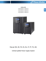
6 – Internal Battery Connection (Models SU20KX and SU40KX Only)
DANGER! LETHAL HIGH VOLTAGE HAZARD!
Potentially lethal high voltage exists within the batteries, even when not connected to a UPS system. Battery connection
should be performed by qualied service personnel only, following all the precautions listed in this manual and adhering to
local electrical codes. Read Section2–ImportantSafetyInstructions before proceeding.
Internal battery connection is for models SU20KX and SU40KX only. Each internal battery pack consists of two strings of batteries: one string
with a black cable and one string with a red cable. The number of internal battery packs varies with model.
6-1 Internal Battery Wiring Diagrams
Review the internal battery wiring diagrams prior to connecting the internal batteries. The UPS system can accept up to four internal battery packs
(each pack consists of two strings; each string consists of 10 batteries). The number of internal battery packs varies with model.
SU40KX shown
SU40KX shown

1
5
9
3
7
11
2
6
10
4
8
12
13
14
UPS System
Battery Back
Connector
UPS System
Battery Back
Connector
Fuse Block Bracket
12
6 – Internal Battery Connection (continued)
SU40KX shown
6-1 Internal Battery Wiring Diagrams (continued)

1
5
9
3
7
11
2
6
10
4
8
12
13
14
1
2
3
4
5
13
6 – Internal Battery Connection (continued)
6-2 Internal Battery Connection Procedure
• Place the UPS system in bypass (or turn it completely off) and turn
off the internal battery circuit breaker switch, located on the rear of
the UPS system.
• Remove the battery access bezels, located on the front of the UPS
system.
• Remove the battery cartridge fuses from each fuse block.
• Disconnect the blue and white jumper cables attached to each fuse
block. Warning:Whendisconnectingthejumpercables,pull
themstraightawayfromthefuseblockwithevenforce.Donot
wigglethemside-to-side,asthismaydamagetheconnector.
• Remove the fuse block bracket. Note its orientation before
removal.
1
2
3
4
5

1
5
9
3
7
11
2
6
10
4
8
12
13
14
7
6
8
9
10
TERMINALS
TERMINALS
SIDE VIEW
SIDE VIEW
14
6-2 Internal Battery Connection Procedure (continued)
• Slide a battery string with a red cable into an empty slot within
the battery compartment. Make sure the battery string is oriented
as shown in the diagram. Note: Start with the empty slots at the
bottom of the battery compartment and work toward the empty
slots at the top of the battery compartment.
• Slide a battery string with a black cable into an empty slot within
the battery compartment, next to the battery string that you inserted
in step 6. Make sure the battery string is oriented as shown in the
diagram. Repeat steps 6 and 7 as needed until all the battery strings
have been inserted into the empty battery slots. Note: Depending
on the model of the UPS system, some battery compartment slots
may remain empty.
• Reconnect the fuse block bracket. (The letters on the fuse block
bracket should be upright when it is in the correct orientation.)
• Connect the blue and white jumper cables on each internal battery
pack to the corresponding fuse block. The labeling next to the fuse
block identifies the correct fuse block for each cable.
• Insert the battery cartridge fuses into each fuse block. The fuses are
interchangeable. Make sure the fuses are firmly snapped into place.
Warning:Batterycartridgefusesmustbeinsertedlastdueto
potentialarcingofconnectors.Blownfusesmustbereplaced
byaqualifiedelectrician.Replaceonlywithfusesofthesame
typeandrating.
6 – Internal Battery Connection (continued)
6
7
8
9
10

1
5
9
3
7
11
2
6
10
4
8
12
13
14
11
13
14
240
12
15
6 – Internal Battery Connection (continued)
6-2 Internal Battery Connection Procedure (continued)
• Use a voltmeter (user-supplied) to test the voltage of each internal
battery pack. Observing proper polarity, connect the voltmeter’s
black probe to the battery pack’s black connector; connect the
voltmeter’s red probe to the battery pack’s red connector. Make
sure the voltmeter’s probes touch the metal contacts inside the
battery pack’s connectors. The battery pack’s acceptable DC
voltage range is between 220V and 280V DC (nominal 240V DC).
If several voltmeter tests yield results outside the acceptable DC
voltage range, contact Tripp Lite for assistance in determining the
possible causes of the incorrect voltage reading before proceeding.
• Connect the black cable for each internal battery pack to the
nearest black connector located inside the UPS system’s battery
compartment. Connect the red cable for each internal battery
pack to the nearest red connector located inside the UPS system’s
battery compartment. Warning:Observeproperpolarityby
connectingnegativetonegative(blacktoblack)andpositive
topositive(redtored).Failuretoobserveproperpolaritywill
damagetheUPSsystemandcreateaseriousriskofpersonal
injuryandpropertydamage.
• Replace the battery access bezels.
• Follow the proper procedure to restart the UPS and re-transfer the
critical load to protected power.
Note: If you need to remove or replace internal battery packs, modify
steps 6 and 7 by removing and/or replacing the existing internal battery
packs, as required.
11
12
13
14

1
5
9
3
7
11
2
6
10
4
8
12
13
14
16
7 – Wiring
DANGER! LETHAL HIGH VOLTAGE HAZARD!
All wiring should be performed by a qualied electrician, in accordance with the warnings in this manual and all applicable
electrical and safety codes. Incorrect wiring may damage the UPS system severely and cause serious personal injury and
property damage. Read Section2–ImportantSafetyInstructions before proceeding.
7-1 Wiring Warnings
• De-energize all input and output power sources of the UPS system before installing cables or making electrical connections.
• Use flexible cable of sufficient length to permit UPS system servicing. The maximum cable length is 10 m (32.8 ft).
• Use ferrule caps to cover termination cables and prevent frayed ends from shorting on the UPS system terminal block.
• Use cabling rated VW-1, FT-1 or better.
• Use cable sleeves and connector clamps.
• The neutral conductor must be the same size as the current conductors.
• Tighten all connections with a torque of at least 3.95 N·m (35 in·lb)
• Confirm that all cables are marked correctly according to their purpose, polarity, phase and diameter.
• If the UPS system’s input/output power source is wye-wye, then “Neutral” and “Ground” must not be connected.
• If the input power source has VNG>0, install a grounded wye secondary isolation transformer with a properly bonded neutral to ground before
the UPS system and input power source.
• For equipment requiring a neutral connection to an IT power distribution system that requires neutral isolation upon disconnect, the disconnect
device must be a four-pole device and must disconnect all line conductors and the neutral conductor. If a disconnect device interrupts the neutral
conductor, it must simultaneously interrupt all line conductors.
• Allow the batteries to charge uninterrupted for 24 hours after the initial wiring connection.
• Observe proper polarity by connecting negative to negative, positive to positive and normal “N” to normal “N”. Failure to observe proper
polarity will damage the UPS system and create a serious risk of personal injury and property damage.
• Observe proper phase by connecting R to R, S to S, T to T and N to N. Source power phase rotation must be verified as RST before powering
the UPS. Failure to observe proper phase will damage the UPS system and create a risk of personal injury and property damage.
• The KX model UPS covered by this manual can be single or dual fed. A separate bypass (reserve) source can be supplied to the UPS input
terminals as desired. The UPS systems are shipped from the factory with the required terminal jumpers (four total) installed to facilitate single
feed connections. If dual feed input is desired, remove the terminal jumpers before wiring both AC main and bypass sources.
7-2 Wiring Preparation
• De-energize all input and output (AC and DC) of the UPS system and external battery cabinet (if present).
• Mark all cables according to their correct purpose, polarity, phase and diameter.
• Review the diagrams in Section7-3 and Section7-4 to familiarize yourself with the terminal blocks.
• Consult the table in Section7-5 to find the correct electrical input/output characteristics for the UPS system.
Note: If the UPS system’s input/output power source is wye-wye, then “Neutral” and “Ground” must not be connected. If the input power source
has VNG>0, install an isolation transformer before the UPS system and input power source, then connect the UPS system’s “Neutral” and
“Ground” together.

1
5
9
3
7
11
2
6
10
4
8
12
13
14
+ –
+
–
External Battery
Cabinet Breaker
Switch
Grounding Terminals
R
T
R
R
T
S
S
N
T
S
N
N+ –
N
Output
External Battery
Connection
17
7 – Wiring (continued)
SU80KX and BP480V40C shown for illustration only. Consult the battery cabinet’s documentation for exact specifications;
battery cabling to be conduit protected.
Single feed typical configuration shown (with factory installed terminal jumpers [x4])
7-3 UPS System Terminal Block Diagram
7-4 External Battery Cabinet Wiring Diagrams

1
5
9
3
7
11
2
6
10
4
8
12
13
14
TO EXTERNAL
BATTERY CABINET
18
7 – Wiring (continued)
7-4 External Battery Cabinet Wiring Diagrams (continued)
7-5 Electrical and Cable Data
SU40KX shown
ExternalBatteryCabinets
B Cabinet: 26AH, 125A Fuses
C Cabinet: 40AH, 160A Fuses
10 Year Cabinet: 55AH, 78AH, 103AH, 140AH; 250A Circuit Breaker
Model Input Output
Recommended
Max. Input,
Bypass (if
used), and
Output Breaker
Size
Input, Reserve,
and Output
Wire Size
Battery
Current at Max.
Load at VDC
Nom
Battery
Current at Max.
Load at LVC
Recommended
Battery Wire
Size
SU20KX 220/380V,
230/400V or
240/415V AC,
3Φ, 4-wire + PE
220/380V,
230/400V or
240/415V AC,
3Φ, 4-wire + PE
50A 10 mm
2
(#8 AWG)
35A 42A 50 mm
2
(1/0 AWG)
SU40KX 220/380V,
230/400V or
240/415V AC,
3Φ, 4-wire + PE
220/380V,
230/400V or
240/415V AC,
3Φ, 4-wire + PE
75A (80A) 25 mm
2
(#4 AWG)
69A 83A 50 mm
2
(1/0 AWG)
SU60KX 220/380V,
230/400V or
240/415V AC,
3Φ, 4-wire + PE
220/380V,
230/400V or
240/415V AC,
3Φ, 4-wire + PE
125A 50 mm
2
(#1 AWG)
103A 124A 50 mm
2
(1/0 AWG)
SU80KX 220/380V,
230/400V or
240/415V AC,
3Φ, 4-wire + PE
220/380V,
230/400V or
240/415V AC,
3Φ, 4-wire + PE
150A 50 mm
2
(1/0 AWG)
138A 165A 50 mm
2
(1/0 AWG)

1
5
9
3
7
11
2
6
10
4
8
12
13
14
1
2
4
3
65
+ –
+ –
+
–
A
A
B
B
A
19
7 – Wiring (continued)
7-6 External Battery Cabinet Wiring
Warning:Externalbatterycabinetsvary.Readtheexternalbatterycabinet’sdocumentationbeforeattemptingtoconnectittotheUPS
system.UseonlyexternalbatterycabinetsthathavebeenapprovedbyTrippLite.
Note: An external battery cabinet is required with models SU60KX and SU80KX. It is optional with models SU20KX and SU40KX. Contact Tripp
Lite for external battery cabinet ordering information.
• De-energize all input and output (AC and DC) of the UPS system
and external battery cabinet, and confirm that the external battery
cabinet breaker switch
A
is off. (If the UPS system has already
been wired to an AC power source, see Section9-6 for shutdown
instructions.)
• Remove the terminal block covers from the UPS system and
external battery cabinet.
• Connect the positive (+), neutral (N) and negative (-) UPS
system connection terminals of the external battery cabinet to the
corresponding positive (+), neutral (N) and negative (-) external
battery connection terminals of the UPS system. See Section7-3
and the external battery cabinet’s documentation for terminal
block diagrams. See Section7-4 for wiring diagrams. See Section
7-5 for cable size requirements. Cabling should be protected by
flexible conduit and routed through the appropriate knockouts in
the terminal block cover. Warning:Observeproperpolarityby
connectingnegativetonegativeandpositivetopositive.Failure
toobserveproperpolaritywilldamagetheUPSsystemand
createariskofpersonalinjuryandpropertydamage.
• Connect the external battery cabinet’s grounding terminal
A
to the
UPS system’s corresponding grounding terminal
B
with a 4 AWG
(5.189 mm) ground cable. Keep the ground cable connected at all
times after installation.
• Connect the UPS system’s grounding terminal
A
to your
facility’s earth ground
B
with a 4 AWG (5.189 mm) minimum
ground cable. Keep the ground cable connected at all times after
installation.
• Replace the terminal block cover of the external battery cabinet. If
you do not plan to wire the AC input/output of the UPS system at
this time, replace the terminal block cover of the UPS system.
1
2
3
4
5
6

1
5
9
3
7
11
2
6
10
4
8
12
13
14
+ –
+ –
+ –
+ –
1
2
3
A
B
+ –
Q4 Q2 Q1Q3
R R S S T T N N R S T N
R R S S T T N N
TO BYPA SS INPUT
CONDUIT
TO MAIN INPUT
CONDUIT
TO BYPA SS INPUT
CONDUIT
TO MAIN INPUT
CONDUIT
R R S S T T N N R S T N
TO INPUT CONDUIT
R R S S T T N N
TO INPUT CONDUIT
R R S S T T N N R S T N
R R S S T T N N
TO BYPA SS INPUT
CONDUIT
TO MAIN INPUT
CONDUIT
TO BYPA SS INPUT
CONDUIT
TO MAIN INPUT
CONDUIT
R R S S T T N N R S T N
TO INPUT CONDUIT
R R S S T T N N
TO INPUT CONDUIT
4A 4B
5A 5B
20
7 – Wiring (continued)
7-7 AC Input/Output Wiring (Single UPS)
• After de-energizing all input and output (AC and DC) of the UPS
system, remove the terminal block cover from the UPS system.
• If you did not connect the ground cable in Section7-6, connect the
UPS system’s grounding terminal
A
to your facility’s earth ground
B
with a 4 AWG (5.189 mm) ground cable. Keep the ground cable
connected at all times after installation.
• Remove the UPS system’s front bezel to expose the circuit
breakers. First, confirm that the main input circuit breaker switch
Q1
and the bypass input circuit breaker switch
Q2
are both off.
Second, confirm that the manual bypass circuit breaker switch
Q3
is off. Third, confirm that the output circuit breaker switch
Q4
is
off.
• Confirm the phase of each cable, then connect the cables according
to the UPS system terminal block diagram in Section7-3. See
Section7-5 for cable size requirements. Cabling should be
protected by flexible conduit and routed through the appropriate
knockouts in the terminal block cover. Warning:Observeproper
phaserotationbyconnectingRtoR,StoS,TtoTandNtoN.
FailuretoobserveproperphasewilldamagetheUPSsystem
andcreateariskofpersonalinjuryandpropertydamage.
4A
Single Fed Input
4B
Dual Fed Input
• Replace the UPS system’s terminal block cover.
5A
Single Fed Input
5A
Dual Fed Input
1
2
3
4
5
/