
Falcon Access Control System
-
--
--
--
--
--
--
--
--
--
--
--
--
--
--
--
--
--
--
--
--
--
--
--
--
--
--
-
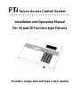
Installation and Operation Manual
For 15 and 20 Function type Falcons
Includes: single wire and type 1 door alarms

PREFERRED TECHNOLOGY INC.
8271 East Gelding Drive
Scottsdale, AZ. 85260
480-991-1259


WARNING: This equipment generates, uses, and can radiate radio
frequency energy and if not installed and used in accordance with the
instructions manual, may cause interference to radio communications.
It has been tested and found to comply with the limits for a Class A
computing device pursuant to Subpart J of Part 15 of FCC rules, which
are designed to provide reasonable protection against such interference
when operated in a commercial enviorment. Operation of this
equipment in a residential area is likely to cause interference in which
case the user at his own expense will be required to take whatever
measures may be required to correct the interference.

Contents
Introduction...............................................................................................................1
Equipment Overview................................................................................................3
The Base Unit..................................................................................................3
The Remote Keypad ......................................................................................4
Connecting Cables.........................................................................................5
Accessories....................................................................................................6
Individual Door Alarms - Expandable ............................................................7
Individual Door Alarms - Single Wire.............................................................8
Installation.................................................................................................................9
Remote Keypad Installation...........................................................................9
Keypad Switches..........................................................................................11
Testing the Keypad.......................................................................................13
Individual Door Alarm Installation - Expandable..........................................13
Mux Box Switches.........................................................................................15
Individual Door Alarm Installation - Single Wire..........................................17
Mux Box Switches.........................................................................................18
Testing the Alarm Wiring..............................................................................19
Testing Mux Box Communications ..............................................................21
Base Unit Installation.....................................................................................21
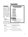
Programming ..........................................................................................................25
General Information......................................................................................25
Programming a New Installation...................................................................26
Function #1 - Set Time/Date........................................................................27
Function #2 - Set Business Hours...............................................................28
Function #3 - Set Holidays ...........................................................................29
Function #4 - Set Building Sizes..................................................................30
Function #5 - Add New Unit..........................................................................31
Function #6 - Suspend Unit..........................................................................33
Function #7 - Release Unit...........................................................................34
Function #8 - Remove Unit...........................................................................35
Function #9 - Set 24hr Unit...........................................................................36
Function #10 - Save on Tape.......................................................................37
Function #11 - Load from Tape...................................................................38
Function #12 - Print Reports........................................................................39
Function #13 - Adjust Contrast.....................................................................40
Function #14 - Open Entrance.....................................................................41
Function #15 - Set Master Code..................................................................42
Function #16 - Door On/Off..........................................................................43
Function #17 - Clear Alarms.........................................................................44
Function #18 - Read Doors..........................................................................45
Function #19 - Unknown Door Print.............................................................46
Function #20 - Set Relay Times..................................................................47

Specifications .........................................................................................................49
Base Unit Specifications...............................................................................49
Remote Keypad Specifications...................................................................49
Alarm Mux Specifications.............................................................................49
WARRANTY...........................................................................................................51


1
Introduction
The PTI Falcon SS is a multi-point access control system capable of hosting up to sixteen
remote keypads or door alarm controllers. Multiple building groups are supported with
multiple units per building. Each unit may be restricted to normal business hours access or
given twenty four hour access. Separately specified business hours for weekdays,
saturdays, sundays, and holidays are supported with up to thirty two preprogrammed
holiday dates. Any individual unit code may be locked out with a few simple keystrokes. All
access activity is logged on a standard computer style printer using standard paper. When
used with the optional door alarm system, all door activity is also logged. The PTI Falcon
also has built-in rechargeable batteries which allow the programming unit to remain
completely operational during a power failure. The simple menu driven programming is
easily mastered using the thirty two character alphanumeric display.
The PTI Falcon cassette tape backup system is unique in the industry, allowing you to
retain a non-volatile copy of your customer data on a standard audio cassette tape with a
standard cassette recorder. This simple concept allows you to separate your customer
data from the machine and allows total elimination of accidentally erased memories.
The PTI remote keypad contains a backlit silicone rubber booted keypad which is highly
weather resistant and a backlit wide temperature liquid crystal display capable of
displaying thirty two characters of alphanumeric data. The keypad unit can be used in total
darkness with no exterior lighting required. The unique display allows the customer to be
given instructions on how to use the keypad as well as a reason for denial in the case of
customer lockout.
Both the programming console and the exterior keypads feature rugged steel construction
with a baked enamel finish. All exterior units contain stainless steel screws, resulting in an
industrial rather than commercial grade product.

2

3
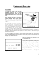
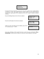
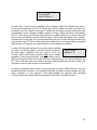
Equipment Overview
The Base Unit
The Base Unit serves as the main pro-
gramming console for the PTI Falcon
access control system. Figure One illus-
trates the front view of the PTI Falcon Base
Unit.
At the top of the unit there is a two line by
sixteen character liquid crystal display.
When the display is not being used for
programming, it will display the current date
and time.
The center of the unit contains a keypad in a
standard telephone arrangement. Often
during programming, you will be asked a
"Yes or No" question. When responding, the
"*" key indicates "No" and the "#" key
indicates "Yes". If you make a mistake when
entering numeric data, the "*" key can also be used to backup or rubout one character at a
time. When the correct data has been keyed in, the "#" key serves as the <Enter> key to
save the data in memory.
The front of the Base Unit contains a 3.5mm standard audio cassette jack, which is used
by the cassette tape memory backup system. This one plug is used for both recording and
playing a tape with the Base Unit.
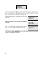
Figure Two illustrates the rear view of the
PTI Falcon Base Unit.
The left most connector is a nine pin D-
subminiature female connector and con-
nects to the remote keypads and other
remote devices. If door alarms are in use,
the alarm relay contacts are also present on
this connector. In addition, when this
connector is plugged in, the internal battery
backup is also connected.
The center connector is a nine pin D-
Figure One
Figure Two

4
subminiature male connector and contains the RS232C serial port if the optional interface
is purchased.
The long right hand connector is a twenty five pin female which connects the serial printer to
the PTI Falcon.
Next to the connectors are the fuse holder and power line connector. The fuse may be
released by inserting a small screwdriver into the notch in the top of the fuse holder and
pressing down on the plastic release clip. WARNING: TO PREVENT ELECTRIC
SHOCK, NEVER REMOVE OR INSERT THE FUSE WITHOUT FIRST UNPLUGGING
THE PTI FALCON BASE UNIT FROM THE POWER OUTLET! The power line
connector contains an integral RF line filter to reduce radio frequency interference with
other electronic devices. WARNING: ALWAYS UNPLUG THE POWER CORD FROM
THE WALL OUTLET FIRST, BEFORE UNPLUGGING THE CORD FROM THE BACK
OF THE PTI FALCON. ALWAYS PLUG THE POWER CORD INTO THE BACK OF
THE PTI FALCON BEFORE PLUGGING THE OTHER END INTO A WALL OUTLET.
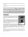
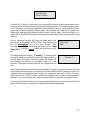
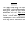
The Remote Keypad
A PTI Falcon access control system may contain multiple
remote keypads such as the one illustrated in Figure Three.
The number of remote keypads will depend on the number of
entry points to the facility through which you desire to control
access.
The Remote Keypad unit contains a silicon rubber booted
keypad in a typical telephone style arrangement. The keypad
contains four small light emitting diodes (LED's) behind the
rubber boot which serve to light the keypad for night use.
These lights are continuously on, although they are not bright
enough to be seen in daylight.
The Remote Keypad unit also contains a thirty two character
liquid crystal display (LCD) arranged as two lines with sixteen
characters per line. The display is fully alphanumeric which
allows complete text to be displayed rather than just numbers.
The LCD also contains an electroluminescent (EL) light panel behind it for night time
viewing. This light only comes on when the "*" key is first pressed on the keypad to begin a
transaction.
Alphanumeric LCD's are available in either "top view" or "bottom view" models, which
specifies the viewing angle for maximum contrast. The PTI Remote Keypad contains a "top
view" LCD, so the best viewing angle will be when the user's line of sight is from above the
display looking down on it.
Figure Three

5
Connecting Cables
The PTI Falcon requires several connecting
cables for proper operation. Figure Four
illustrates the power cord for the PTI Falcon.
When installation is complete and you are
ready to turn on the system, the female end
of the power cord will plug into the power
outlet on the back of the PTI Falcon and the
male end will plug into a 120 VAC 60Hz
outlet. WARNING: TO AVOID SHOCK
HAZARD, NEVER PLUG THE MALE END
OF THE POWER CORD INTO A WALL
OUTLET WITH THE FEMALE END
EXPOSED!
All of the remote keypads and other devices
communicate with the PTI Falcon through
the remote patch cord. This cord consists of
a 9 pin male connector which plugs into the
corner connector on the PTI Falcon. A three
position terminal block is on the other end. It
is on this terminal block that the field wiring
from the remote devices will terminate.
Systems with PTI door alarms will have a
second three position terminal block on the
end of this cable which provides the relay
contacts to trigger the alarm siren.
If you have purchased a printer for the PTI
Falcon, it will come with a printer cable
similar to the one illustrated in Figure Six.
The printer cable has a twenty five pin male
connector on each end. One end plugs into
the printer connector on the back of the base
unit, and the other end plugs into the printer.
This cable is reversible, so direction is not
important.
Figure Four
Figure Five
Figure Six

6
If you have purchased the optional computer
interface for the PTI Falcon, you will have a
computer interface cable similar to the one
pictured in Figure Seven. The PTI Falcon
end of the cable will have a nine pin female
connector and will plug into the nine pin
serial port connector on the back of the PTI
Falcon base unit. The other end of the cable
will have either a nine pin female connector
or a twenty five pin female connector,
depending on which was ordered. This end
will plug into the serial port on your computer
or modem. This cable is not reversible, so
the PTI Falcon end of the cable will be
labeled appropriately.
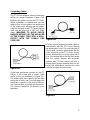
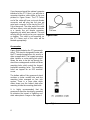
Accessories
Figure Eight illustrates the PTI gooseneck
stand. This stand is designed to mate with
the PTI remote keypad when it is used in a
drive up application. The keypad mounting
plate contains a center wiring hole which
allows the wire to be fed up through the
stand from underground conduit and three
mounting holes which match the keypad
backplate mounting holes. The mounting
holes are tapped for an 8-32 machine
screw.
The bottom plate of the gooseneck stand
contains a center conduit hole and four
mounting holes arranged on four inch
centers. There is a cover plate which
slides down over the bottom plate after
mounting to hide the mounting plate bolts.
It is highly recommended that the
gooseneck stand be electrically grounded
to minimize the impact of lightning and
static atmospheric charge on the keypad.
Figure Seven
Figure Eight

7
Individual Door Alarms - Expandable
The PTI Falcon supports the use of PTI individual door alarms. PTI door alarms require the
use of door alarm multiplexer (mux) boxes, such as the one pictured in Figure Nine. A mux
box contains a master circuit board
capable of multiplexing forty eight
doors. If the box must multiplex more
than forty eight doors, up to three
expansion boards may be added to
the master board. Each expansion
board adds an additional forty eight
doors to the box, bringing the
maximum number of doors on one
box to one hundred ninety two.
Each building on the property must
have its own multiplexer box or
boxes. Multiplexer boxes are con-
nected to the PTI Falcon base unit
through the same three wire RS485
interface as the remote keypads.
Each alarmed door must have a
magnetic door switch mounted on
the door. The mux box will connect to
one wire from each switch in addition
to a common wire which connects to
all switches. Fifty conductor
telephone cable is often used for the
individual door wiring. If one cable is
used for one mux board, it allows
forty eight conductors for the forty
eight door switches and two conductors for the common wire in order to increase the
effective wire size for the common wire.
In addition to the door wiring and communication wiring, each master mux board requires
12 VAC power in order for the board to operate. A single 12 VAC plug-in style transformer
is often used to power all of the multiplexer boxes from a central point. This allows all of the
field wiring to be low voltage.
Each mux box contains a rechargeable battery pack to sustain the operation of the alarm
box during power outages and a tamper switch to detect break-ins to the mux box itself.
Figure Nine

8
Individual Door Alarms - Single Wire
The PTI Falcon may also utilize PTI single wire door alarms rather than expandable door
alarms. The PTI single wire system uses a Door Control Unit (DCU) box at the head end
of a three conductor cable which runs from unit to unit. Each unit contains a small Door
Interface Unit (DIU) circuit board mounted in a standard single gang electrical box which
connects to the three conductor cable. Figure Ten illustrates the appearance of the DCU
box and DIU boards. Use of the DIU modules allows individual identification electronically
of each door even though separate wires are not run from each door. Each DCU box can
support up to one hundred DIU modules on a single run of three conductor wire using 22
gauge wire. The PTI Falcon base unit communicates with the DCU the same way as with
an expandable door alarm mux box, and cannot tell the difference between the two.
Figure Ten

9
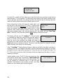
Installation
Remote Keypad Installation
Open the Remote keypad by removing the four stainless steel button head machine screws
on the sides of the keypad case. The front and back half will now separate. Mount the back
plate to the desired keypad location using the three keyed holes.
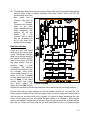
Figure Eleven is a diagram of
the circuit board found in the
front half of the Remote keypad.
The items of interest to the
installer are as follows:
(1) Depluggable terminal strip
TS1 with six terminals at
the bottom left of the circuit
board.
(2) Depluggable terminal strip
TS2 with six terminals at
the bottom right of the
circuit board.
(3) Power line fuse on the
bottom left side of the
board.
(4) Relay contact fuse on the
bottom right side of the
board.
(5) Red rotary switch near the
bottom center of the board.
(6) Eight position DIP switch
under the red rotary switch.
Figure Eleven

10
It is necessary to wire the following items to the remote keypad for proper operation:
(1) Low voltage power and safety ground.
(2) RS485 communication wires from the base unit.
(3) Relay contact wires from the keypad relay to the entrance device.
Installation of wiring should proceed as follows:
(1) Install the RS485 communication cable from the keypad to the base unit in the office. A
22 AWG shielded twisted pair with 22 AWG ground wire is best for this purpose.
Terminate the wires as follows:
TS2, pin 1 - Red Wire - to red terminal of remote patch cable
TS2, pin 2 - ground - to white terminal of remote patch cable
TS2, pin 3 - Black Wire - to black terminal of remote patch cable
(2) Install the relay contact wires to the entrance operator; both normally open and normally
closed relay contacts are available on the following terminals:
TS2, pin 4 - Normally open relay contact
TS2, pin 5 - Relay common contact
TS2, pin 6 - Normally closed relay contact
Most electric gate operators require a normally open contact (pins 4 & 5). Some
electric door strikes require a normally closed contact (pins 5 & 6). WARNING:
WIRING THE RELAY TO THE OPERATING DEVICE WILL INTRODUCE THE
OPERATING DEVICE CONTROL VOLTAGE INTO THE REMOTE KEYPAD
CABINET. THE INSTALLER MUST VERIFY THAT THIS DOES NOT
CONSTITUTE A HIGH VOLTAGE! THE PTI KEYPAD IS NOT DESIGNED FOR
THE PRESENCE OF HIGH VOLTAGE WITHIN THE KEYPAD CASE.
(3) Install low voltage power wiring into the keypad from the low voltage power transformer
into TS1 as follows:
TS1, pin 1 - 12 VAC
TS1, pin 2 - 12 VAC
TS1, pin 3 - ground
The PTI remote keypad will operate on voltages from 12V to 24V AC or DC, however,
12VAC is recommended for best operation. If you purchased a complete PTI Falcon
system, a 12VAC transformer is supplied with the system.
(4) The PTI remote keypad has two optional input circuits for reading auxiliary switches.

11
Auxiliary input one is used to monitor an alarm switch input, which is typically used to
detect forced opening of the gate or door controlled by the keypad. Auxiliary input two
can be used to lock out the keypad from accepting codes based on a contact closure
from an auxiliary device. This input is sometimes wired to a vehicle loop detector,
which forces the customer to be in a vehicle before the keypad will allow access. If
auxiliary contacts are used they should be dry contacts wired as follows:
TS1, pin 4 - auxiliary contact one
TS1, pin 5 - auxiliary contact common
TS1, pin 6 - auxiliary contact two
Keypad Switches
The keypad switches must be properly set. The PTI Falcon system considers odd
numbered keypads to be entrance keypads and even numbered keypads to be exit
keypads. The first entrance keypad should be unit number one, the second unit number
three, etc. Your exit keypads will then be units number two, four, etc. The unit number for
each keypad is set with the red rotary switch. For unit numbers higher than nine, DIP switch
number four should be turned on which adds ten to the rotary switch number. DIP switch
number five may be used to add twenty to the rotary switch setting. It is possible to set the
keypad number to any value from zero to thirty nine. Be aware that the PTI Falcon system
reserves remote address zero for its own use, and a keypad set to be unit zero will not
communicate with the base unit.
Finally, you must set the position of the eight DIP switches as needed for proper keypad
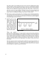
operation. The switch functions are summarized in the following table:
When DIP switch one is turned on, an "X" will appear on the keypad display as each digit
of the access code is entered, rather than the actual digit. This may be set to your
individual preference.
The PTI Falcon uses a 1200 baud communication rate, therefore DIP switch four should be
Switch 1: OFF = echo code on display; ON = no echo
Switch 2: OFF = disable auxiliary input one; ON = enable
Switch 3: OFF = disable auxiliary input two; ON = enable
Switch 4: OFF = 9600 baud communication; ON = 1200
baud
Switch 5: OFF = add zero to unit number; ON = add ten
Switch 6: OFF = add zero to unit number; ON = add twenty
Switch 7: OFF = not used; ON = not used
Switch 8: OFF = high comm line impedance; ON = low

12
set ON. The keypad only reads switch four at power up, so if you must change switch four,
momentarily kill power to the keypad after it has been correctly set.
Switch eight when ON, places a communication line terminating resistor across the RS485
data leads. This switch should be turned ON if the keypad is the last keypad on the RS485
communication wire, otherwise set it OFF.
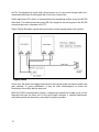
Figure Twelve illustrates a typical wiring scheme for a two keypad gate access system.
In this case, the twelve volt supply transformer for the keypad power has been located in the
gate operator. In some installations, it may be more advantageous to locate this
transformer in the office with the base unit.
With the RS485 communication scheme, a keypad can typically be located as far as four
thousand feet from the base unit. As the wire length increases, a shielded twisted pair
cable with ground wire becomes a necessity for proper operation.
Figure Twelve
Page is loading ...
Page is loading ...
Page is loading ...
Page is loading ...
Page is loading ...
Page is loading ...
Page is loading ...
Page is loading ...
Page is loading ...
Page is loading ...
Page is loading ...
Page is loading ...
Page is loading ...
Page is loading ...
Page is loading ...
Page is loading ...
Page is loading ...
Page is loading ...
Page is loading ...
Page is loading ...
Page is loading ...
Page is loading ...
Page is loading ...
Page is loading ...
Page is loading ...
Page is loading ...
Page is loading ...
Page is loading ...
Page is loading ...
Page is loading ...
Page is loading ...
Page is loading ...
Page is loading ...
Page is loading ...
Page is loading ...
Page is loading ...
Page is loading ...
Page is loading ...
Page is loading ...
-
 1
1
-
 2
2
-
 3
3
-
 4
4
-
 5
5
-
 6
6
-
 7
7
-
 8
8
-
 9
9
-
 10
10
-
 11
11
-
 12
12
-
 13
13
-
 14
14
-
 15
15
-
 16
16
-
 17
17
-
 18
18
-
 19
19
-
 20
20
-
 21
21
-
 22
22
-
 23
23
-
 24
24
-
 25
25
-
 26
26
-
 27
27
-
 28
28
-
 29
29
-
 30
30
-
 31
31
-
 32
32
-
 33
33
-
 34
34
-
 35
35
-
 36
36
-
 37
37
-
 38
38
-
 39
39
-
 40
40
-
 41
41
-
 42
42
-
 43
43
-
 44
44
-
 45
45
-
 46
46
-
 47
47
-
 48
48
-
 49
49
-
 50
50
-
 51
51
-
 52
52
-
 53
53
-
 54
54
-
 55
55
-
 56
56
-
 57
57
-
 58
58
-
 59
59


PTI Falcon 20 Operating instructions
- Type
- Operating instructions
Ask a question and I''ll find the answer in the document
Finding information in a document is now easier with AI
Other documents
-
 PTI security systems Falcon XT Installation guide
-
Chamberlain LiftMaster Q Installation guide
-
 Tesla Motors 2AEIM-1048598 User manual
-
 PTI security systems VP keypad controls entry Operating instructions
-
Ingersoll-Rand Thermo KingCRR DF MP3000 Maintenance Manual
-
PSC Falcon 4400 Series User manual
-
Datalogic 4420 Operating instructions
-
-
-
Beam OC800 User manual


