VEVOR VP245 User manual

Type
User manual

The VEVOR VP245 is a high vacuum pump designed for a variety of applications including freeze drying, vacuum packaging, and degassing. Its 5 CFM free air displacement and ultimate vacuum of 3x10⁻¹ Pa (0.003 mbar, 25 microns) make it suitable for creating a near-perfect vacuum. It features a 1/2 HP motor and 1/4"SAE, 3/8"SAE, and 1/2"ACME male intake fittings. With a 330ml oil capacity, it has dimensions of 385x210x315mm and weighs 9.3kg.

The VEVOR VP245 is a high vacuum pump designed for a variety of applications including freeze drying, vacuum packaging, and degassing. Its 5 CFM free air displacement and ultimate vacuum of 3x10⁻¹ Pa (0.003 mbar, 25 microns) make it suitable for creating a near-perfect vacuum. It features a 1/2 HP motor and 1/4"SAE, 3/8"SAE, and 1/2"ACME male intake fittings. With a 330ml oil capacity, it has dimensions of 385x210x315mm and weighs 9.3kg.

Model:VP245
VACUUM PUMP
Have product questions? Need technical suppo? Please feel free to contact us:
CustomerSe[email protected]
NEED HELP? CONTACT US!
This is the original instruction, please read all manual instructions carefully before
operating. VEVOR resees a clear interpretation of our user manual. The appear-
ance of the product shall be subject to the product you received. Please forgive us
that we won't inform you again if there are any technology or software updates
on our product.
01
VACUUM PUMP
02
SAFETY INSTRUCTION
This device complies with Pa 15 of the FCC Rules. Operation is
subject to the following two conditions:(1)This device may not
cause harmful inteerence, and (2)this device must accept any
inteerence received, including inteerence that may cause
undesired operation.
This symbol, placed before a safety comment, indicates a kind of
precaution, warning, or danger. Ignoring this warning may lead to
an accident. To reduce the risk of inju, re, or electrocution,
please always follow the recommendation shown below.
Warning - To reduce the risk of inju, user must read instructions
manual carefully .
Before operating this appliances, please read instructions manual carefully and
save these instruction. basic safety precautions should always be followed
including the following :
WARNING
Household Use Only.
WARNING: Hot Suace-To reduce the risk of burns, do not touch.
CAUTION: To reduce the risk of electric shock, do not expose to rain, store indoors.
CAUTION: To reduce the risk of electric shock, use indoors only.
WARNING:RIsk of inju-Do not direct air steam at body.
Utilisez seulement des menages.
AVERTISSEMENT:Suace chaude-Pour reduire le risque de brolures,ne touchez pas.
ATTENTION: Pour reduire le risque de choc electrique, ne pas exposer a la pluie.
Stockez indoorsduce100
ATTENTION: Pour reduire le risque de choc electrique, utilisez uniquement a linter-
ieur. AVERTISSEMENT:RIsque de blessure-Ne pas courant dair directe sur le corps.
03
Exhaust Fitting
(Oil Fill Cap)
Sight Glass
Die-Cast Aluminum
Housing
Oil Drain
Handle
Fan Cover
Motor
Base
PUMP COMPONENTS
OPERATING MANUAL
1.Before using your vacuum pump
In all cases, motors are designed for operating voltages plus or minus 10% of the
normal rating. Single voltage motors are supplied fully connected and ready to
operate.
(1)Check to be sure the voltage and frequency at the outlet match the specica-
tions on the pump motor decal. Check the ON-OFF switch to be sure it is in the OFF
position before you plug the pump into an outlet.Remove and discard the exhaust
cap from the end of the pumps handle.
(2)The pump is shipped without oil in the reseoir.Before staing the pump, ll
it with oil.Remove the Exhaust Fitting cap and add oil until oil just shows in the
bottom of the sight glass. The approximate oil capacity of the pump is
180~800ml(reference the technical data).
(3)Replace the Exhaust Fitting cap and remove the cap from one of the inlet
pos. Turn the motor switch to ON.When the pump runs smoothly, replace the cap
on the inlet po. This may take from two to 30 seconds depending on the ambient
temperature.After the pump runs for approximately one minute check the sight
glass for proper oil level. The level should be even with the sight glass oil level line.
Add oil if necessa.
Note:When the pump is running, the oil level should be even with the line on
the sight glass. Under lling will result in poor vacuum peormance.Over lling can
result in oil blowing from the exhaust.
2.To shut down your pump after use
To help prolong pump life and promote easy staing. Follow these procedures
for shut down.
(1)Close the manifold valve between the pump and the system.
(2)Remove the hose from the pump inlet.
(3)Cap the inlet po to prevent any contamination or loose paicles from entering
the po.
04
TO MAINTAIN YOUR HIGH VACUUM PUMP
1.Vacuum pump oil:
The condition and type of oil used in any high vacuum pump are extremely
impoant in determining the ultimate attainable vacuum. We recommend the use of
High Vacuum Pump Oil.This oil has been specically blended to maintain maximum
viscosity at normal running temperatures and to improve cold weather stas.
2.Oil Change Procedure
(1)Be sure the pump is warmed up.
(2)Remove the OIL DRAIN cap. Drain contaminated oil into a suitable container
and dispose of properly. Oil can be forced from the pump by opening the inlet
and paially blocking the exhaust with a cloth while
the pump is running .Do not operate the pump for more than 20 seconds
using this method.
(3)When the ow of oil has stopped, tilt the pump forward to drain residual oil.
(4)Replace the OIL DRAIN cap.Remove the exhaust tting and ll the reseoir
with new vacuum pump oil until the oil just shows at the bottom of the sight
glass. The approximate oil capacity of the pump is 180-800ml(reference the technical
data).
(5)Be sure the inlet pos are capped then turn on the pump. Allow it to run for
on minute then check the oil level space. If the oil is below the sight glass OIL
LEVEL line add oil slowly (with the pump running )until the oil reaches the OIL
LEVEL line.Replace the exhaust tting, making sure the inlet is capped and the
drain cap is tight.
(6)
a)If the oil is badly contaminated with sludge that forms when water is allowed
to collect in the oil,you may need to remove the oil reseoir cover and wipe
it out.
b)Another method of dealing with heavily contaminated oil is to force the oil from
the pump reseoir. To do this, allow the pump to run until it is warmed up. While the
pump is still running remove the oil drain cap. Slightly restrict the exhaust. This will back-
pressure the oil reseoir and force the oil from it, caring more contamination.
When the oil ceased to ow, turn o the pump.
Repeat this procedure as required until the contaminatin is removed.
Replace the OIL DRAIN cap and rell the reseoir to the proper level with
fresh pump oil.
05
TROUBLESHOOTING GUIDE
Your pump has been for dependable use and long life. If something should to
wrong, the following guide will help you get the pump back into seice as quickly
as possible.
If diassembly of the pump is required, please check your warranty.The warranty
may be voided by misuse or customer tampering which results in the pump being
inoperable.
1.Failure To Sta
Check the line voltage. The pump ned to sta at±10% line voltage (loaded)
at 320F.At extremes,switching between the standard run windings may occur.
2.Oil leakage
(1)Be sure the oil is not a residual accumulation from spillage, etc.
(2)If leakage exists the module cover gasket or the shaft seal may need replacing.
If leakage exists in the area of the oil drain plug you may need to reseal the plug
using a commercial pipe thread sealer.
3.Failure To Pull A Good Vacuum
(1)Be sure the vacuum gauge and all connections are in good condition and leak
free.You can conrm leakage by monitoring the vacuum with a thermistor gauge
while applying vacuum pump oil at connections or suspected leak points.
The vacuum will improve briey while the oil is sealing the leak.
(2)Be sure the pump oil is clean. A badly contaminated pump may require several
oil ushes.
(3)Be sure the oil is at the proper level.For maximum pump operation, the oil must
be even with OIL LEVEL line on the sight glass when the pump is running. Do not
oveill---- operating temperatures will cause the oil expand, so it will appear at a
higher level than when the pump is not running. To check the oil level, sta the
pump with the inlet capped, Check the oil level in the sight glass. Add oil if necessa.
06
COMMON TROUBLE SHOOTING
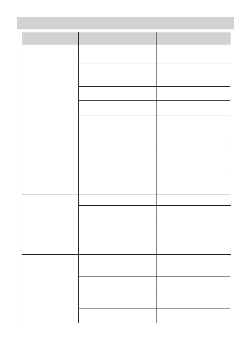
Failure Description
Low Vacuum
Oil Leakage
Oil Injection
Hard Staing
Fault Cause Solution
1.The air inlet cap on the spare po
side of the air inlet po is loose.
Tighten the air inlet cap
Replace the rubber ring
Refuel to the centerline of the oil
gauge
Replace with new oil
Clean the oil inlet hole and lter
mesh
Check the connected pipe
container to prevent leakage
Check the size of the pumped
container, recalculate and select
the appropriate pump model
Check, repair, or replace the
pump with a new one
2. The rubber ring inside the air
inlet cap on the spare po side of
the air inlet po is damaged
3. Insucient oil
4. The pump oil is emulsied
and unclean
5. The oil inlet hole of the pump
is blocked or the oil supply is
insucient
6. Leakage of pipe container
connected to the pump
7. Improper pump selection
1. The oil seal is damaged
1. The oil temperature is too low
2. The motor or power supply is
faulty
3. Foreign objects fall into the
pump
4. The power supply voltage is
too low
Check and repair
Check and eliminate
Check the power supply voltage
Note: If the above solutions do not solve your problem, please contact the nearest dealer, or
send your pump to a professional repair center, and we will do our best to see you.
2. The oil tank connection is
loose or damaged
Replace the oil seal
Tighten the screws and replace
the O-ring
8. The pump has been used for too
long, and the clearance is
increased due to the wear of pas
1.Too much oil
2.The inlet pressure is too high
for a long time
Drain the oil to the oil level line
Select the appropriate pump to
increase the pumping speed
The air inlet is ventilated,
repeatedly stas the motor or
heats the pump oil
07
TECHNICAL PARAMETER
Model
Voltage
Free Air
Displacement
CFM
L/min
Pa
mbar
Motor
Microns
Intake Fitting
Oil Capacity (ml)
Dimensions(mm)
Net Weight(kg)
Ultimate
Vacuum
Dual Stage Vacuum Pump
VP245
5.0
3x10⁻¹
0.003
330
385x210x315
9.3
25
1/2 HP
142
1/4"SAE male;3/8"SAE male; 1/2"ACME male;
115V~/60Hz
08
1.Before using your vacuum pump
In all cases, motors are designed for operating voltages plus or minus 10% of the
normal rating. Single voltage motors are supplied fully connected and ready to
operate.
(1)Check to be sure the voltage and frequency at the outlet match the specica-
tions on the pump motor decal. Check the ON-OFF switch to be sure it is in the OFF
position before you plug the pump into an outlet.Remove and discard the exhaust
cap from the end of the pumps handle.
(2)The pump is shipped without oil in the reseoir.Before staing the pump, ll
it with oil.Remove the Exhaust Fitting cap and add oil until oil just shows in the
bottom of the sight glass. The approximate oil capacity of the pump is
180~800ml(reference the technical data).
(3)Replace the Exhaust Fitting cap and remove the cap from one of the inlet
pos. Turn the motor switch to ON.When the pump runs smoothly, replace the cap
on the inlet po. This may take from two to 30 seconds depending on the ambient
temperature.After the pump runs for approximately one minute check the sight
glass for proper oil level. The level should be even with the sight glass oil level line.
Add oil if necessa.
Note:When the pump is running, the oil level should be even with the line on
the sight glass. Under lling will result in poor vacuum peormance.Over lling can
result in oil blowing from the exhaust.
2.To shut down your pump after use
To help prolong pump life and promote easy staing. Follow these procedures
for shut down.
(1)Close the manifold valve between the pump and the system.
(2)Remove the hose from the pump inlet.
(3)Cap the inlet po to prevent any contamination or loose paicles from entering
the po.
Fan cover
Cross screw
Fan
Motor cover
Power supply cords
Power switch
Undee washer
Bearing
Motor rotor
Capacitor box
Centrifugal switch
Motor stator
Casing
Capacitor
Handle
Trestle
Gas cap
The air inlet nozzle
Screw
Front rota-vane
Spring
Cap board
Exhaust and oil inlet tting
Die cast aluminum housing
Sight glass
Oil drain
Oil drain screw O-ring
Screw
Sealing ring
Screw
Rubber foot
Base plate
Self tapping screw
Back-pump cover
Oil seal
Back-pump body
Back-rota -vane
Back-pump rotor
Spring
Middle fense
Front-pump body
Front-pump rotor
Front cover
Oil seal
O type ring
Screw
EXPLODED DRAWING
09
Manufacturer: MECHANICAL AND ELECTRICAL PRODUCTS CO., LTD
AddressChengxi Industrial Zone,Wenling, Zhejiang,317500, China
Made In China
10
E-mail: CustomerSeice@vevor.com
  • Page 1 1
  • Page 2 2
  • Page 3 3
  • Page 4 4
  • Page 5 5
  • Page 6 6
  • Page 7 7
  • Page 8 8
  • Page 9 9
  • Page 10 10
  • Page 11 11
  • Page 12 12

VEVOR VP245 User manual

Type
User manual

The VEVOR VP245 is a high vacuum pump designed for a variety of applications including freeze drying, vacuum packaging, and degassing. Its 5 CFM free air displacement and ultimate vacuum of 3x10⁻¹ Pa (0.003 mbar, 25 microns) make it suitable for creating a near-perfect vacuum. It features a 1/2 HP motor and 1/4"SAE, 3/8"SAE, and 1/2"ACME male intake fittings. With a 330ml oil capacity, it has dimensions of 385x210x315mm and weighs 9.3kg.

Ask a question and I''ll find the answer in the document

Finding information in a document is now easier with AI