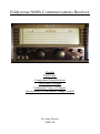
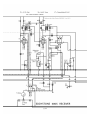
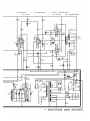
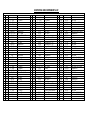
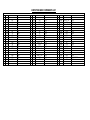
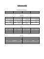
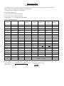
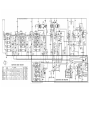
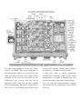
Eddystone 680X User manual

Type
User manual

Eddystone 680X is a communications receiver that offers a wide range of features and capabilities for receiving and processing radio signals. With its advanced design and construction, the Eddystone 680X is well-suited for various applications, including:

  • Communication: The Eddystone 680X can receive and decode a wide range of communication signals, including AM, FM, CW, and SSB. This makes it an ideal choice for monitoring and communicating with other stations, both locally and internationally.

  • Signal analysis: The Eddystone 680X's built-in signal analysis capabilities allow users to examine and measure various characteristics of received signals. This information can be used for troubleshooting, interference identification, and other technical purposes.

Eddystone S680X Communications Receiver
Circuits
Parts Lists
Component Identification
Test Point Voltages
Underside View of Chassis
An overview of the Band Change Switch
By Andy Davies
GWØJXM
Circuits
I’ve been repairing an Eddystone S680X Receiver and
I found the original circuit that I had a little fragile
and a little bit difficult to work with as some of the
numbers and details are missing where the page has
been folded. As I intend to keep the radio I thought
I’d invest a bit of time redrawing the circuit and this
has been a useful exercise in getting familiar with the
circuit. Having used the circuit that I retraced for a
little while I realised that I was writing additional
information on the circuit, things like valve pin
numbers etc and I figured that if that helped me then
I believe it would also help others.
Originally I made the circuit fit onto two A4 sheets
(UK standard paper size) and again having used the
circuit I thought that it would be more use to me in a
slightly larger scale so I’ve reshuffled the circuit so as
to make it very easy to print as four A4 sheets and
glue them together side by side. I’ve allowed for a
generous overlap so you should find it a simple
matter of trimming the edges to get rid of any excess
and the drawing can then be folded down to A4 size
for storage.
I have included a copy of the full circuit reduced
down to a single sheet and this may be helpful should
you want to view the whole circuit in one piece on the
computer screen rather that have to print out the four
page version. In both cases they are the same circuit
although I have rearranged the position of some of
the components so that they are in a more logical
position. I’ve created the circuit in Adobe Photoshop
and I’ve made a little video on YouTube about how I
went about this*1
Parts List
I haven’t compared the whole of the circuit of my
radio with the drawing but I think it is generally the
same. I haven’t found any resistors or capacitors that
are not as specified on the drawing, other than R69
which, although on the original circuit wasn’t listed
on the parts list, but there are some very obvious
differences. Remember that my radio is an S680X and
the drawing is designated as a 680X.
In my radio, the S680X, there is only one mains fuse
and it has a double pole mains switch where as the
680X drawing shows two mains fuses and a single
pole mains switch.
Component Identification
The other difference is that the ‘Standby’ switch in my
radio is positioned immediately after the Smoothing
choke Ch1 and before C115 whereas on the circuit
diagram the standby switch is positioned after C115.
A point to note is that if you open circuit the
‘Standby’ switch and then unplug the radio one or
more of the capacitors, C114 and/or C115 depending
on which circuit you have, will remained charged for
a little while. I know this as I made that mistake and it
got me.
Test Point Voltages
I’ve included a sheet of Test Point Voltage Values;
remember that values are for test equipment with, by
today’s standards, fairly low sensitivity. On the
manufacturer’s original list you may notice that there
are two C-‘s and two E-‘s.
I’ve made provision to identify them by the valve pin
numbers as they could have different values whereas
the likelihood of the other duplicated test points
having different values is unlikely. For instance test
points Z and A- are hard wired together.
Underside View of Chassis
The underside view of the chassis is based on a
photograph of my radio and I have orientated this
with the knobs towards the operator which is the way
I do things as opposed to the manufactures original
which has the radio facing away from the operator.
Overview of the Band Change
Switch
In this section I show how the Band Change switch is
configured and hopefully make it a little easier to
understand how it operates.
Video*1
I have made several videos of the work I have done so
far on the radio and if you search YouTube for my call
sign ‘gw0jxm’ (the third character is a zero) or search
for Eddystone S680X you should find them.
Im not a Radio Expert just a keen amateur, I’ve
taken reasonable care in preparing this information,
I hope that you find it helpful.
Andy Davies
GWØJXM
EDDYSTONE 680X COMPONENTS LIST
CAPACITORS
C1
3 23 pF
Air Trimmer
3 23 pF
Air Trimmer
C79
0.1 uF
Tub. Paper
C2
10 pF
Silvered Mica
3 pF
Silvered Mica
C80
400 pF
Silvered Mica +/- 2%
C3
3 23 pF
Air Trimmer
3 23 pF
Air Trimmer
C81
0.01 uF
Tub. Paper
C4
3 23 pF
Air Trimmer
3 23 pF
Air Trimmer
C82
100 pF
Silvered Mica +- 2%
C5
3 23 pF
Air Trimmer
10 367.75 pF
F.C. Tuning
C83
0.1 uF
Tub. Paper
C6
3 23 pF
Air Trimmer
25 pF
Silvered Mica +/- 5%
C84
400 pF
Silvered Mica +/- 2%
C7
100 pF
Silvered Mica
0.1 uF
Tub. Paper
C85
10 pF
Silvered Mica
C8
0.0005 uF
Moulded Mica
0.1 uF
Tub. Paper
C86
8 uF
Tub. Elect. 350v DC Wkg
C9
10 367.75 pF
1st RF Tuning
0.01 uF
Tub. Paper
C87
0.01 uF
Moulded Mica
C10
25 pF
Silvered Mica +/- 5%
10 pF
Ceramic
C88
0.01 uF
Tub. Paper
C11
0.01 uF
Tub. Paper
7000 pF
Silvered Mica +/- 1%
C89
0.1 uF
Tub. Paper
C12
0.01 uF
Tub. Paper
3625 pF
Silvered Mica +/- 1%
C90
0.1 uF
Tub. Paper
C13
0.1 uF
Tub. Paper
1625 pF
Silvered Mica +/- 1%
C91
0.1 uF
Tub. Paper
C14
0.0005 uF
Moulded Mica
900 pF
Silvered Mica +/- 1%
C92
0.1 uF
Tub. Paper
C15
0.1 uF
Tub. Paper
440 pF
Silvered Mica +/- 1%
C93
0.1 uF
Tub. Paper
C16
0.1 uF
Tub. Paper
3 23 pF
Air Trimmer
C94
100 pF
Silvered Mica
C17
20 pF
Silvered Mica
3 23 pF
Air Trimmer
C95
100 pF
Silvered Mica
C18
3 23 pF
Air Trimmer
3 23 pF
Air Trimmer
C96
0.5 uF
Tub. Paper 200v DC Wkg
C19
6 pF
Silvered Mica
10 pF
Silvered Mica
C97
0.01 uF
Tub. Paper
C20
3 23 pF
Air Trimmer
3 23 pF
Air Trimmer
C98
30 uF
Tub. Elect. 15v DC Wkg
C21
3 pF
Silvered Mica
20 pF
Silvered Mica
C99
30 uF
Tub. Elect. 15v DC Wkg
C22
3 23 pF
Air Trimmer
20 pF
Silvered Mica
C100
0.01 uF
Moulded Mica
C23
3 pF
Silvered Mica
3 23 pF
Air Trimmer
C101
0.5 uF
Tub. Paper 200v DC Wkg
C24
3 23 pF
Air Trimmer
10 367.75 pF
Osc. Tuning
C102
30 uF
Tub. Paper 15v DC Wkg
C25
3 23 pF
Air Trimmer
12 pF
Ceramic
C103
0.002 uF
Moulded Mica
C26
10 367.75 pF
2nd RF Tuning
200 pF
Ceramic
C104
0.1 uF
Tub. Paper
C27
25 pF
Silvered Mica +/- 5%
50 pf
Silvered Mica
C105
0.002 uF
Moulded Mica
C28
0.01 uF
Tub. Paper
0.0005 uF
Moulded Mica
C106
0.01 uF
Moulded Mica
C29
0.1 uF
Tub. Paper
0.0005 uF
Moulded Mica
C107
8 pF
Silvered Mica
C30
0.01 uF
Tub. Paper
0.1 uF
Tub. Paper
C108
100 pF
Silvered Mica
C31
100 pF
Silvered Mica
0.1 uF
Tub. Paper
C109
100 pF
Silvered Mica
C32
0.1 uF
Tub. Paper
400 pF
Silvered Mica +/- 2%
C110
-
B.F.O. Pitch Capacitor
C33
0.1 uF
Tub. Paper
800 pF
Silvered Mica +/- 2%
C111
0.01 uF
Tub. Paper
C34
20 pF
Silvered Mica
800 pF
Silvered Mica +/- 2%
C112
0.01 uF
Tub. Paper
C35
3 23 pF
Air Trimmer
-
Crystal Phasing capacitor
C113
0.01 uF
Tub. Paper
C36
3 pF
Silvered Mica
20 pF
Silvered Mica
C114
16 uF
Tub. Elect. 450v DC Wkg
C37
6 pF
Silvered Mica
0.01 uF
Moulded Mica
C115
40 uF
Tub. Elect. 350v DC Wkg
C38
3 23 pF
Air Trimmer
500 pF
Silvered Mica +/- 2%
-
-
-
C39
3 pF
Silvered Mica
400 pF
Silvered Mica +/- 2%
-
-
-
EDDYSTONE 680X COMPONENTS LIST
RESISTORS
R1
33K
1W
150R
0.5W
R47
3M +/- 5%
0.5W
R2
1K
0.5W
1K5
0.5W
R48
1K5
0.5W
R3
33K
1W
12R
0.5W
R49
6K8 +/- 5%
0.5W
R4
1K
0.5W
150R
0.5W
R50
470K
0.5W
R5
1K
0.5W
100K
0.5W
R51
620R +/- 5% 1W
0.5W
R6
15K
0.5W
2K2
0.5W
R52
470K
0.5W
R7
1K
0.5W
2K2
0.5W
R53
3M +/- 5%
0.5W
R8
33K
1W
10K
0.5W
R54
100K
0.5W
R9
1K
0.5W
1K
0.5W
R55
2K2
0.5W
R10
1M
0.5W
22K
0.5W
R56
27K
1W
R11
270K
0.5W
470K
0.5W
R57
5K Pot
-
R12
10K
0.5W
15K
0.5W
R58
10K
0.5W
R13
270K
0.5W
68R +/- 5%
0.5W
R59
2M
0.5W
R14
1M
0.5W
470K
0.5W
R60
47K
0.5W
R15
12R
0.5W
560R
0.5W
R61
10K
0.5W
R16
470K
0.5W
68R +/- 5%
0.5W
R62
10K Pot
-
R17
470K
0.5W
1M
0.5W
R63
270K
0.5W
R18
68R +/- 5%
0.5W
100K +/- 5%
0.5W
R64
5R Pot
-
R19
150R
0.5W
100K +/- 5%
0.5W
R65
6K8
0.5W
R20
12R
0.5W
470K
0.5W
R66
2K7
WIRE WOUND
R21
470K
0.5W
1M
0.5W
R67
4K7
0.5W
R22
470K
0.5W
500K Pot
-
R68
22K
1W
R23
68R +/- 5%
0.5W
1K5
0.5W
R69
12R
0.5W
Eddystone 680X
Transformers and Choke
T1 1st I.F.
T2 Crystal Unit
T3 2nd I.F.
T4 3rd I.F.
T5 Audio Output
T6 B.F.O.
T7 Mains
Ch.1 Soothing
Switches
SW.1 Pri 1st R.F.
SW.2 Sec 1st R.F.
SW. 3 Pri 2nd R.F.
SW.4 Sec R.F.
SW.5 Pri
Frequency Changer
SW.6 Sec
Frequency Changer
SW.7 Pri
Oscillator
SW.8 Sec
Oscillator
SW.9 Crystal
Phasing
Sw. 10 Selectivity
Max - Min
Sw. 11 Selectivity
Max - Min
SW.12 A.G.C.
Off/On
SW.13 Noise
Limiter Off/On
SW.14 B.F.O.
Off/On
SW.15 Mains
Off/On
SW.16 Standby
Coils
L1 Range 1 1st R.F.
L2 Range 1 1st R.F.
L3 Range 1 1st R.F.
L4 Range 1 1st R.F.
L5 Range 1 1st R.F.
L6 Range 1 2nd R.F.
L7 Range 2 2nd R.F.
L8 Range 3 2nd R.F.
L9 Range 4 2nd R.F.
L10 Range 5 2nd R.F
L11 Range 1 F.C.
L12 Range 2 F.C.
L13 Range 3 F.C.
L14 Range 4 F.C.
L15 Range 5 F.C.
L16 Range 1 Osc
L17 Range 2 Osc
L18 Range 3 Osc
L19 Range4 Osc
L20 Range 5 Osc
Valves
V1,2 R.F. Amplifier 6BA6
V3 Frequency Changer 6BE6
V4 H.F. Oscillator 6AM6/Z77
V5,6 I.F. Amplifier 6BA6
V7 Demodulator /A.G.C. 6AL5/D77
V8 Audio Amplifier 8D5/6BR7
V9 Phase Splitter 8D5/6BR7
V10, 11 Push Pull Output 6AM5/EL91
V12 B.F.O. 6BA6
V13 Noise Limiter/ ‘S’ Meter 6AL5/D77
V14 Power Rectifier 5Z4G
V15 Voltage Stabiliser VR150/30
Eddystone 680X
Test Point Voltage Values
Two different sets of voltages are given for two different meter sensitivities an Avo and a Weston meter.
These values are taken with reference to the chassis.
1) Receiver set to 1000 Kc/s on Range 5
2) Aerial shorted out.
3) The RF control set to maximum.
4) AF gain Control set to minimum
A tolerance of +/- 5% can be accommodated.
There is no test point ‘I’
Test
Point
AVO
1,000 O.P.V
Your
reading
Test
Point
AVO
*See note
Weston
1,000
O.P.V.
Your
reading
A
205 V
218 V
U
0.7 V
0.8 V
B
80 V
84 V
V
18 V
22 V
C
0.8 V
1 V
W
15 V
22 V
D
210 V
218 V
X
0.8 V
0.8 V
E
80 V
83 V
Y
218 V
220 V
F
1 V
1.9 V
Z
220 V
225 V
G
212 V
220 V
A-
11.5 V
11.5 V
H
100 V
100 V
B-
85 V
85 V
J
1.1 V
1.2 V
C- pin 1 V13
142 V
150 V
K
85 V
100 V
C- pin 7 V13
142 V
150 V
L
206 V
206 V
D-
252 V
260 V
M
88 V
93 V
E- pin 6 V14
240 V AC
245 V AC
N
1 V
1 V
E- pin 4 V14
240 V AC
245 V AC
O
206 V
210 V
F-
150 V
150 V
P
75 V
80 V
Heaters xx
6.3 AC
Q
1 V
1 V
Heaters yy
6.3 AC
R
11.5 V
11.5 V
S
20 V
25 V
Total HT Current: 110 mA
T
18 V
25 V
Mains Voltage
*Note, these values have been copied from an original copy of the general instruction manual and it’s been suggested to me that AVO’ refers to
an AVO 7 which has a sensitivity of 500 ohms per volt. By the way an AVO 8 has a sensitivity of 20,000 ohms per volt and of course a 21st
century digital meter has a much higher sensitivity of 1to 20 M ohms. Andy Davies gw0jxm Dec 2011
Notes
Date of test
The above photograph is of my own radio
and it’s an S680X. The circuit diagrams in
this document is based on a circuit that I had
with my radio and that is the same circuit
diagram as the one for the 680X on the
Eddystone User Group web site (as of
December 2011) You can tell the original
Eddystone drawing that I have redrawn as it
has 2 off C37’s associated with switch 6 and
the parts list doesn’t identify R69 (which in
my radio is a 12 ohms ½ watt resistor)
I have only done a partial component
identification showing some of the major
components as a guide to finding ones way
around the radio chassis but it should help.
You can find the manufacturers original
information at the Eddystone User Groups
web site.
Eddystone S680X communications receiver.
Band change switch
An overview of the band change switch
By Andy Davies
GWØJXM
*Special note. This information is based on an Eddystone S680X serial No GL1824 with the component identification taken from a circuit diagram
with an unspecified issue number for a 680X from the Eddystone user group website. 8th December 2011
Eddystone S680X Communications Receiver.
Band Change Switch
I think that the most daunting thing in the receiver is the band change switch and I figure
the sooner I get to grips with it or I should say ‘them’ the better. At first sight it looks
horrendously complicated but when you get in close they’re really not at all complicated.
The band change switch comprises of eight identical, five position, double pole wafer
switches. So although the band change switch is referred to as switches 1 to 8 it would
have been better to refer to it as switches 1 to 16 Each switch has two different moving ring
contact arrangement on either side.
Each wafer switch of course has a side that faces the front of the radio and I’ll refer to that as
the ‘f’ side and the side facing the back of the radio I’ll refer to as the ‘b’ side.
The ‘f’ sides of each of the switches are simple single-pole five-way selector switches and
they look like the switch on the left in the image below, it has one closed contact and 4 open
contacts. ‘C’ of course denotes the common contact.
The inner ring is the moving contact on
both sides of the switch; they are of course
‘ganged’ together to move as one but they
are insulated from one another.
Terminal 1 of side ‘f’ is connected to
terminal 1 of side ‘b’ and terminal 2 of
side ‘f is connected to terminal 2 of side
‘b’ and so on. The ‘f’ and ‘b’ ring contacts
each have their own common terminals.
Remember that in the image to the left
you are seeing the ‘b’ side of the switch
as if you were looking through the ‘f’
side from the front of the radio.
All eight (16) band change switches are mechanically coupled by a common shaft and they
are identical.
The ‘b’ side of the switch comprises of another five-way switch but this one, instead of
selecting one of the five poles, it grounds or decouples each of the four poles that are not
selected by the ‘f’ switch, it has one open contact position and four closed contacts.
The switch is shown in the number one position i.e. fully anticlockwise, (30Mhz)
All of the eight wafer switches used for band selection are of the same construction.
Eddystone S680X Communications Receiver
Band Change Switch.
The forward facing contacts
The band change switches select the inductively coupled tuned circuits for four sections of
the radio.
1) The first R.F. stage. 2) The second R.F. stage.
3) The frequency changer. 4) The Oscillator.
Each of the four sections above, are
controlled by two of the wafer switches
and once you understand the operation of
one section you’ll see that, in terms of
wiring, the switching of all four sections
are practically identical.
In each section the common terminal of one
of the ‘f’ side contacts of one switch
connects to one end of the primary of the
chosen coil (tuned circuit).
So, in the first R.F. section the common
terminal of the ‘f’ side of the first switch
(shown below on the left) connects to the
primary of the chosen tuned circuit.
The common terminal of the ‘f’ side of the
second switch in that section (shown below
on the right) connects to one end of the
secondary of the chosen tuned circuit.
Only coils L1 and L5 are shown but L2
connects to switch position 2 in each case
and L3 connects to position 3 etc.
In each section the coil with the lowest
identification number connects to switch
position 1, with the next highest being
connected to switch position number 2 etc.
Note that in each section
the highest frequency’s
coils are positioned
nearest to the wafer
switch.
The 30MHz coils are
connected to the switch
with strip rather than
wire.
Eddystone S680X Communications Receiver
Band Change Switch.
The backward facing contacts
The common contacts of the ‘b’ sides of all eight band change switches are connected to ground,
either directly or via a capacitor. There’s an exception with Switch 1.
The common contact of Switch 1 may be connected to ground via the ‘AE’-‘A’ link on the back of the
radio otherwise it is connected to one side of the dipole aerial. See a full circuit diagram of the radio
for details.
Whereas both ‘f’ sides of each switch selects the required coil to be connected into the circuit, both
of the ‘b’ sides of each switch in each section ‘de-select’ the coils that are chosen by the ‘f’ side. Any
coil that is not ‘de-selected’ is grounded or decoupled, either directly or via a capacitor to the
chassis.
Again only L1 and L5 are shown below but L2 connects to position 2 of the switch and L3 to
position 3 etc.
In each tuning section the lowest numbered coil connects to contact 1 of that sections switch, with
the next higher numbered coil connecting to contact 2 and so on.
Remember that in the image you are seeing above the ‘b’ side of the switches
are seen as if you were looking through the ‘f’ side from the front of the radio.
Note that the common terminal ‘C’ for the ‘f’ and the ‘b’ sides of the switch are not the same
terminal, they are separated by one index position.
So, in a nutshell, in all cases the front facing contacts select the required coil, the back
facing contacts de-select that coil from being grounded.
Eddystone S680X Communications Receiver
Band Change Switch.
Under view of the tuning section showing the band change switch locations.
The front facing contacts select
the required coil, the back
facing contacts de-select that
coil from being grounded.
All eight of the wafer switches
of the band change are identical.
Switch position 1 = band 1
Switch position 2 = band 2 etc.
Band 1 30 to 12.3 MHz
Band 2 12.5 to 5.3 MHz
Band 3 5.7 to 2.5 MHz
Band 4 2.5 to 1.11 MHz
Band 5 1120 to 480 kHz
*Special note. This information is based on an Eddystone S680X serial No GL1824 with the component identification taken
from a circuit diagram with an unspecified issue number from the Eddystone user group website.
Created by Andy Davies GWØJXM 8th December 2011
  • Page 1 1
  • Page 2 2
  • Page 3 3
  • Page 4 4
  • Page 5 5
  • Page 6 6
  • Page 7 7
  • Page 8 8
  • Page 9 9
  • Page 10 10
  • Page 11 11
  • Page 12 12
  • Page 13 13
  • Page 14 14
  • Page 15 15
  • Page 16 16
  • Page 17 17

Eddystone 680X User manual

Type
User manual

Eddystone 680X is a communications receiver that offers a wide range of features and capabilities for receiving and processing radio signals. With its advanced design and construction, the Eddystone 680X is well-suited for various applications, including:

  • Communication: The Eddystone 680X can receive and decode a wide range of communication signals, including AM, FM, CW, and SSB. This makes it an ideal choice for monitoring and communicating with other stations, both locally and internationally.

  • Signal analysis: The Eddystone 680X's built-in signal analysis capabilities allow users to examine and measure various characteristics of received signals. This information can be used for troubleshooting, interference identification, and other technical purposes.

Ask a question and I''ll find the answer in the document

Finding information in a document is now easier with AI