Page is loading ...

Power Instrumentation, LCR analysis
Gain Phase Analysis, PAV
Current sensors and probes
Transducers
7 3rd Street
Holbrook NY 11741USA
Tel: 631 615 6279
148 Beecham Road
Reading, Berkshire
RG30 2RE England
Tel: 44 1788 519911
Fax: 44 870 0940135
VAT Reg: GB 724 3670 40
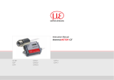
Instructions and installation for the CTH dc current transducers Ver 1.0 Aug 15, 2016
<<< Important! Serial number of sensor head and signal conditioner should match >>>
Introduction
The CTH dc current transducers will produce a linear voltage or current output proportional to the input current.
Depending on the CTH model, the actual input current and proportional output are indicated on the transducer
label. For example, using a CTH/50A/10V/SC/24Vdc with 1 primary turn, a 0-10Vdc output will be produced for a
0-50Adc input. With ac current signals, the CTH transducers can be used to provide an instantaneous output
signal that can be viewed using an oscilloscope.
Installation and safety
<<<< WARNING! >>>>
ALL CTH CURRENT SENSOR HEADS MUST BE PAIRED WITH THEIR
CORRESPONDING SIGNAL CONDITIONERS (TERMINATION BOX)
The CTH transducer should only be used in dry indoor environments. If the current sensor is detachable,
ensure that the sensor and signal conditioner are matched - refer to serial numbers. When using CTH split
core models (part numbers containing 'SC' i.e. CTH/50/10/SC/24Vdc), ensure the CTH split core is closed
correctly before use and that the conductor is positioned centrally, in the middle 30% of the hole. To prevent
damage, check for correct connection of the power input and measurement output. Installation should be
carried out by authorized personnel, familiar with the risks and dangers of electrical systems. Allow a minimum
warm up period of 15 minutes (required when measuring small current signals) for best accuracy. If an external
dc offset control is fitted, ensure that the CTH output = 0V or 4mA when zero primary current is flowing. For
best performance, high sensitivity models CTH Type 1 and CTH Type 3, with a full scale range less than 5A,
may require dc offset adjustment in situ, during commissioning
1

User manual Contents
Signal Conditioner Connections................................................................................................................................................. 3
Specifications.............................................................................................................................................................................. 4
Signal Conditioner Sizes Types 1, 2, 3, 4, 4 mini, 5, 6, 7, 8, 8 mini, 8EE, 8F and 9z................................................................. 5
Signal Conditioner Sizes type G, type 10 and type 11................................................................................................................ 6
Sensor dimensions CTH type 1 and type 2................................................................................................................................ 7
Sensor dimensions CTH type 3.................................................................................................................................................. 8
Sensor dimensions CTH type 4 and 4 mini................................................................................................................................ 9
Sensor dimensions CTH type 5.................................................................................................................................................. 10
Sensor dimensions CTH type 6 and type 7................................................................................................................................ 11
Sensor dimensions CTH type 8 and 8 mini................................................................................................................................ 12
Sensor dimensions CTH type 8F and type 8EE......................................................................................................................... 13
Sensor dimensions CTH type 9z and type G.............................................................................................................................. 14
Sensor dimensions CTH type 10 and type 11............................................................................................................................ 15
2

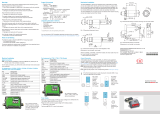
Connections and installation for Types 1, 2, 3, 4, 4 mini, 5, 6, 7, 8, 8 mini, 8EE, 8F and 9z
connections
Hi Lo Neg Pos
Output Power
Screw terminals are provided for the power input and output connections. The terminal block connections are
labeled. Ensure that the primary current direction is correct, refer to direction arrow above transducer aperture.
A hole is provided to securely mount the transducer.
Note the 125Vdc input on the 125Vdc-24Vdc or 125Vdc-12Vdc power converters is not polarity sensitive
CTH Types: 1, 2, 3, 4, 4 mini, 5, 6, 7, 8, 8 mini, 8EE, 8F and 9z connections
Early CTH type 4 & CTH type 8 have lug/fork connections (up to ~2008) or if specified . In this case the cable
connection end is labelled. Later CTH type 4/8 units are fitted with a flanged connection box similar to the
standard CTH signal conditioner. CTH type 4, CTH type 4 mini, CTH type 8 and CTH type 8 mini
Power +
(Red)
Power –
(Black)
Input –
(White)
Input +
(Green)
The input current, output type and required power will be indicated on the rating label
Protection
A bi-polar dc current can be applied to the CTH voltage output version, but not with 4-20mA versions.
Accidental connection of output terminals to either a dc or ac voltage source, >15V, may result in damage.
Internal fast acting fuses protect the auxiliary power supply input and measurement output
Maximum isolation between power input terminals and output terminal is 500Vdc.
Maximum isolation between the current transducer aperture to power input terminals or output terminal is 2000V.
Gain and Offset adjust and calibration
The CTH are supplied calibrated. Internal adjustment of dc offset drift and gain is possible, this should be made
using the correct calibration procedure. Although yearly calibration adjustment is not required, it is recommended
that periodical comparisons are made to known calibration standards.
3

CTH DC current transducer general specifications
Ranges
Depending on core type: 1A / 2A / 5A / 10A / 20A / 30A / 40A / 50A /
100A / 200A / 500A / 1000A / 2000A / 3000A / 4000A / 5000A / 6000A /
10000A / 20000A / 25000A / 30000A / 35000A / 40000A Amps peak
Outputs
0-100mV, 0-1V, 0-2V, 0-5V, 0-10V or 0-20mA, 4-20mA or 5-25mA
outputs. All CTH outputs can be bipolar / instantaneous. Non-standard
outputs are available.
Core type Through hole or split core clamp type, based on dc Hall Effect sensing
Insulation voltage rating Type 1, 2 & 5 rated insulation (Galvanic) 2.5kVpk 1 min 50/60Hz.
Type 6 & 7 3kVpk 1 min 50/60Hz. Type 4 & 8 5kVpk 1 min 50/60Hz
Power input
5V / 12Vdc / 24Vdc / wide range 9-36Vdc / 48Vdc / 72Vdc / 110Vdc /
125Vdc / 250Vdc / 115Vac / 230Vac - all fuse, polarity and surge
protected
125Vdc power input, voltage range is 100Vdc to 150Vdc, max current
draw 25mA
48Vdc power input, voltage range is 36Vdc to 72Vdc, max current
draw 80mA
24Vdc power input, voltage range is 18Vdc to 36Vdc, max current
draw 140mA
12Vdc power input, voltage range is 9Vdc to 18Vdc, max current draw
200mA
5Vdc power input, voltage range is 4.5Vdc to 6Vdc, max current draw
300mA
Accuracy ±0.5% for a non split core, ±1.0% for a split core. Conditions +23°C
±5°C, traceable to UKAS NPL/NIST USA
Working temperature range
Typically -20°C - 65°C (can be extended, check for exact model).
Functional temperature range –20°C - 70°C (check for each model).
CTH types 1 & 2 are –40°C - 85°C (sensor head only)
Protection Input fuse, output fuse, power input polarity diode, spike suppression
Frequency response
Depending on sensor type/model. Type 1 & 2 DC- 150kHz max. Type
5, 6, 7, 8 & 9 split cores are DC-10kHz max. Standard HF cut-off filter
is 1.5kHz (other values available)
Adjustment Internal dc offset and gain controls
Mounting
All signal conditioners and sensors have fixing points. Current sensors
up to 400A can be mounted on the signal conditioner case or via a
cable.
Approvals CE Marked, IEC1010 cat II & IEC348, UL/CSA rated materials. Self
extinguishing materials to UL94V0
Warranty 2 year warranty
Specification notes
Recommended Measurement range is 5% to 100% range
The output load impedance for a 10Vdc output should be >5kohms
The output load impedance for a 4-20mA output should be <500ohms
Current draw
125Vdc power input, voltage range is 100Vdc to 150Vdc, max current draw 25mA
48Vdc power input, voltage range is 36Vdc to 72Vdc, max current draw 80mA
24Vdc power input, voltage range is 18Vdc to 36Vdc, max current draw 140mA
12Vdc power input, voltage range is 9Vdc to 18Vdc, max current draw 200mA
5Vdc power input, voltage range is 4.5Vdc to 6Vdc, max current draw 300mA
4


CTH Current sensor Type 4
SENS
SIZE
SENSOR DIMENSIONS inches and mm WT.
LBS
A B C D E F G H J K L M N P
inches 3 1/8 5 1 1/4 2 2 2 1/16 7/16 3 1/4 3 1/4 7/16 7/16 5/8 5/16 17/64 2
mm 79.38 127 31.75 50.8 50.8 52.39 11.11 82.55 82.55 11.11 11.11 15.88 7.94 6.75 2
CTH Current sensor Type 4 Mini
SENS
SIZE
SENSOR DIMENSIONS inches and mm WT.
LBS
A B C D E F G H J K L M N P
inches 3 1/8 4 3/4 1 1/8 1 1/2 1 9/16 1/2 2 1/8 NA 3/8 1/4 3/8 1/4 5/16 0.75
mm 79.38 101.6 19.05 28.58 38.1 39.69 12.7 53.98 NA 9.53 6.35 9.53 6.35 7.94 0.75
9


CTH Current sensor Type 8
SENS
SIZE
SENSOR DIMENSIONS inches and mm WT.
LBS
A B C D E F G H J K L M N P
inches 3 1/8 5 1 1/4 2 2 2 1/16 7/16 3 1/4 3 1/4 7/16 7/16 5/8 5/16 17/64 2
mm 79.38 127 31.75 50.8 50.8 52.39 11.11 82.55 82.55 11.11 11.11 15.88 7.94 6.75 2
CTH Current sensor Type 8 Mini
SENS
SIZE
SENSOR DIMENSIONS inches and mm WT.
LBS
A B C D E F G H J K L M N P
inches 3 1/8 4 3/4 1 1/8 1 1/2 1 9/16 1/2 2 1/8 NA 3/8 1/4 3/8 1/4 5/16 0.75
mm 79.38 101.6 19.05 28.58 38.1 39.69 12.7 53.98 NA 9.53 6.35 9.53 6.35 7.94 0.75
12

CTH Current sensor Type 8F
SENS
SIZE
SENSOR DIMENSIONS inches and mm WT.
LBS
A B C D E F G H J K L M N P
inches 5 3/8 5 1/4 1 5/8 2 1/4 2 5/8 2 11/16 1 1/16 3 1/4 4 1/8 9/16 NA 5/8 NA 1/4 2.8
mm 136.53 133.35 41.28 57.15 66.68 68.26 26.99 82.55 104.78 14.29 NA 15.88 NA 6.35 2.8
CTH Current sensor Type 8EE
SENS
SIZE
SENSOR DIMENSIONS inches and mm WT.
LBS
A B C D E F G H J K L M N P
inches 7 3/4 7 1/4 1 5/8 4 1/4 3 5/8 3 7/8 1 1/8 5/12 6/14 1/2 NA 5/8 NA 5/16 4.5
mm 196.85 184.15 41.28 107.96 92.08 98.43 28.58 10.58 10.89 6.35 NA 15.88 NA 7.94 4.
13

CTH Current sensor Type 9z
SENS
SIZE
SENSOR DIMENSIONS inches and mm WT.
LBS
A B C D E F G H J K L M N P
inches 7 3/16 3 3/4 1 1/8 1 ¼ X 4 ½ 2 1/16 3 1/2 1 5 1 7/8 5/16 NA 3/8 1/4 3/16 2.8
mm 182.56 95.25 28.5
8
31.75 X 107.95 52.39 88.9 25.4 127 47.63 7.94 NA 9.53 6.35 4.76 2.8
CTH Current sensor Type G
SENS
SIZE
SENSOR DIMENSIONS inches WT.
LBS
A B C D E F G H J K L M N P
Type G 7 ¾ 12 1 ¾ 3 x 6 ½ 6 3 7/8 5/8 6 ½ 10 ¾ 5/8 5/8 5/8 5/16 9/32 12.3
14

CTH Current sensor Type 10
SENS
SIZE
SENSOR DIMENSIONS inches and mm WT.
LBS
A B C D E F G H J K L M N P
inches 10 13 3/4 1 3/4 5 ½ X 6 6 1/2 5 5/8 8 3/4 11 1/2 1/4 1 1/2 5/8 5/16 9/32 13
mm 254 349.25 44.45 139.7 X 152.4 165.1 127 15.88 222.25 292.1 6.35 38.1 15.88 7.94 7.14 13
CTH Current sensor Type 11
SENS
SIZE
SENSOR DIMENSIONS inches and mm WT.
LBS
A B C D E F G H J K L M N P
inches 21 21 2 13 X 13 10 1/2 10 1/2 1 1/2 18 18 1 1/2 1 1/2 5/8 11/16 3/8 22
mm 533.4 533.4 50.8 330.2 X 330.2 266.7 266.7 38.1 457.2 457.2 38.1 38.1 15.88 17.46 9.53 22
15
/