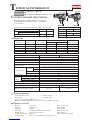
Makita HR3541FC is a powerful and versatile combination hammer designed for professional use. Equipped with advanced technology, it delivers exceptional performance in various applications. Its 1,100W motor provides ample power for drilling, hammering, and chiseling tasks in concrete, wood, and metal. The SDS-Max shank system ensures compatibility with a wide range of drill bits and accessories.
Makita HR3541FC is a powerful and versatile combination hammer designed for professional use. Equipped with advanced technology, it delivers exceptional performance in various applications. Its 1,100W motor provides ample power for drilling, hammering, and chiseling tasks in concrete, wood, and metal. The SDS-Max shank system ensures compatibility with a wide range of drill bits and accessories.


-
 1
1
-
 2
2
-
 3
3
-
 4
4
-
 5
5
-
 6
6
-
 7
7
-
 8
8
-
 9
9
-
 10
10
-
 11
11
-
 12
12
-
 13
13
-
 14
14
-
 15
15
-
 16
16
-
 17
17
-
 18
18
-
 19
19


Makita HR3541FC is a powerful and versatile combination hammer designed for professional use. Equipped with advanced technology, it delivers exceptional performance in various applications. Its 1,100W motor provides ample power for drilling, hammering, and chiseling tasks in concrete, wood, and metal. The SDS-Max shank system ensures compatibility with a wide range of drill bits and accessories.
Ask a question and I''ll find the answer in the document
Finding information in a document is now easier with AI
Related papers
Other documents
-
Kmart 43298914 User manual
-
Hitachi DH 50MB Technical Data And Service Manual
-
BenQ GW2780 User manual
-
-
-
-
-
Winado 195408160231 User manual
-
-