Page is loading ...

MULTIcont X-16 speed controller # 7 2271
MULTIPLEX Modellsport GmbH & Co. KG • Neuer Weg 2 • D-75223 Niefern • www.multiplex-rc.de
MULTICont
X
-16 instructions # 72271
These operating instructions are an integral part of this
product. They contain important information and safety
notes, and should therefore be kept in a safe place at all
times. Be sure to pass them on to the new owner if you
ever dispose of the product.
1. S
PECIFICATION
MULTIcont X-16
Cell count, Ni-Cd / Ni-MH
6 - 8 /
2 Li-Poly cells
Continuous current 16 A
Pulse frequency ~ 6 kHz
Receiver power supply (BEC):
BEC voltage 5 V
BEC current max. 1 A
Dissipated power of BEC controller max. 2.5 W
Dimensions (excl. cables) 27 x 20 x8 mm
Weight incl. cables 17 g
2. S
AFETY NOTES
• Read the instructions before using the controller.
• Avoid heat build-up: do not obstruct air circulation.
• Do not connect drive battery with reversed polarity:
Incorrect polarity at the battery terminals will instantly
ruin the speed controller.
For this reason: • red wire to POSITIVE terminal (+),
• black wire to NEGATIVE terminal (-)
If you do not wish to solder the motor connections directly,
we recommend the use of MPX 6-pin connectors # 85213 /
85214 for connecting the controller / battery and motor /
controller.
• When soldering or working on the motor or controller:
Always disconnect the battery
(short-circuit / injury hazard).
• When test-running or operating the power system:
Do not hold the motor in your hand when running it; hold the
model securely. Check that there is ample space for the
propeller to rotate. Remove any object from the vicinity of
the propeller which could be sucked into it or blown away by
it (clothing, small items, paper etc.). Never stand in or in
front of the plane of rotation of the propeller (injury hazard).
3. S
PECIAL FEATURES
• BEC with low-voltage cut-off: (recommended up to max. 8
cells) with automatic cell count detection.
• Power-on guard: when you connect the drive battery, the
controller stays in power-on guard mode. The motor can
only be switched on if you move the throttle stick to the idle
position after connecting the battery. If not, the LED flashes.
• Overload protection: if the controller overheats or is
overloaded, the controller switches off the power supply to
the motor. To re-activate the system you must disconnect
the battery, then re-connect it.
• Over-voltage protection:
The controller switches off if the voltage is above 16 V.
4. C
ONNECTING THE CONTROLLER TO THE MOTOR
Note: to connect the controller soldering may be necessary.
Soldering requires a certain level of skill and care, as the
system will only work reliably if the joints are made well:
• use only a type of solder designed for electronic work
• do not use acid-based soldering flux
• do not over-heat parts or heat them for too long
• if you are not sure, ask an experienced modeller to help
1. Motor suppression:. if the motor you wish to use is not
supplied with factory-fitted suppressors, we strongly
recommend that you fit the suppressor set, # 85020, to
avoid interference to the RC system.
2. Solder the controller’s motor cables to the motor
The motor cables on the controller are marked “MOTOR”;
solder them to the drive motor:
usually with direct-drive motors: yellow Æ “+” ; blue Æ “-”
3. Check the direction of motor rotation
If the motor rotates in the wrong direction (e.g. with a
geared motor), swap over the cables at the motor
terminals.
5. U
SING THE CONTROLLER FOR THE FIRST TIME
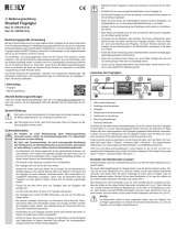
1. Connect the controller’s servo connector (REC) to
the receiver.
MPX RC systems: to channel 4 = throttle / motor
2. If you have a programmable RC system, set the servo
travel for the throttle channel to 100% on both sides.
3. Move the throttle stick (and trim
) to the desired idle
end-point / motor OFF position.
4. Switch on the transmitter.
5. Connect the drive battery to the speed controller.
Caution: reversed polarity instantly wrecks the unit!
If the LED now flashes, the controller is in power-on guard
mode Æ disconnect the drive battery from the controller,
reverse the throttle channel at the transmitter (servo
reverse), then re-connect the drive battery Æ ready.
• Important:
• First switch the transmitter ON, then connect the
drive battery
If the LED flashes, the power-on guard is active Æ
move the throttle stick to idle Æ controller is ready!
• First disconnect the drive battery from the controller,
then switch the transmitter OFF.
6. BEC = B
ATTERY ELIMINATING CIRCUIT
BEC means: the receiver and servos draw current from the
drive battery. Do not use a separate receiver battery.
• Note: please note that the BEC circuit of the MULTIcont X-
16 can only supply a current of 1 A for the model’s receiving
system. In practice this means: with 7 cells max. 3 servos,
with 8 cells max. 2 servos; above 8 cells: do not use BEC.
The current drain varies according to the power of the servo,
the frequency of control use, and the stiffness of the control
surface linkages (!). If you have no means of measuring the
BEC current: carry out a test-run on the ground, and operate
the servos constantly until the low-voltage cut-off is triggered
(= flat drive battery). The servos should respond to the sticks
without hesitation or jitter throughout the test period, and the
controller should be no more than warm at the end of it.
If your model is fitted with more servos than stated, you must
disable the BEC circuit and use a separate receiver battery.
This is done by cutting through the red wire
(+) in the servo
lead attached to the speed controller.
7. LOW VOLTAGE CUT-OFF
The MULTIcont X-16’s low-voltage cut-off circuit switches off
the drive motor when the drive battery is almost flat. This
ensures that there is still sufficient energy for the BEC
system, so that the model can be controlled to a safe
landing. A marked fall-off in motor speed is your warning that
the battery is almost discharged; start the landing approach
as soon as you detect this. If the battery voltage falls to 65%
of the idle voltage, the controller will switch off the motor.
However, you can switch the motor back on again for a short
period if you first move the throttle stick to the idle / motor
OFF position, then advance it again.
/