APC AV G-Type Rack Power Filter 120V 15A User guide
- Category
- Surge protectors
- Type
- User guide
This manual is also suitable for

Installation and
Operation
G-Type Rack Power Filter
G5BLK
120V
15A
Page is loading ...

Contents
APC A/V G-Type Rack Power Filter
i
General Information ....................................................... 1
Overview . . . . . . . . . . . . . . . . . . . . . . . . . . . . . . . . . . . . . . . . . . . . . . . . 1
Inventory . . . . . . . . . . . . . . . . . . . . . . . . . . . . . . . . . . . . . . . . . . . . . . . . 1
Safety . . . . . . . . . . . . . . . . . . . . . . . . . . . . . . . . . . . . . . . . . . . . . . . . . .1
Components . . . . . . . . . . . . . . . . . . . . . . . . . . . . . . . . . . . . . . . . . . . . . 2
Installation ...................................................................... 3
Install the Unit . . . . . . . . . . . . . . . . . . . . . . . . . . . . . . . . . . . . . . . . . . .3
Connect A/C Power . . . . . . . . . . . . . . . . . . . . . . . . . . . . . . . . . . . . . . .3
Operation ........................................................................ 5
Display Interface . . . . . . . . . . . . . . . . . . . . . . . . . . . . . . . . . . . . . . . . . 5
Configuration .................................................................. 9
Troubleshooting .......................................................... 10
Common problems and solutions . . . . . . . . . . . . . . . . . . . . . . . . . . 10
Contact APC APV Technical Support . . . . . . . . . . . . . . . . . . . . . . . 10
Specifications ............................................................... 11
Warranty . . . . . . . . . . . . . . . . . . . . . . . . . . . . . . . . . . . . . . . . . . . . . . . 11
Español ......................................................................... 13
Français (Canada) ........................................................ 25
Page is loading ...

1APC A/V G-Type Rack Power Filter: General Information
General Information
Overview
The APC
®
AV G-Type Rack Power Filter protects high-performance audio and video system equipment
from damage due to power surges, spikes, and lightning strikes.
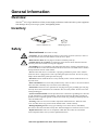
Inventory
Safety
• Electrical Hazard: For indoor use only.
• CAUTION - Do not install this device if there is not at least 10 meters (30 feet) or more of
wire between the electrical outlet and the electrical service panel.
• Risk of electric shock. Do not plug into another relocatable power tap.
• Contains always on receptacles. To reduce the risk of electric shock, disconnect the unit
from the power source before servicing the equipment.
• Overloading. Do not overload the wall outlet where this device is being connected. Do not
overload this device. Ensure the total load to this device does not exceed that which is listed in
the Specifications section of this manual.
• Power. Ensure this device is connected to a properly grounded AC power source. Further
ensure the device is plugged into a source providing the required 120 Vac. Do not use a plug
adapter which defeats the ground pin of the AC plug.
• Placement. Do not install this device on any unsteady surface. Do not install this device on
any heat source.
• Water and Moisture. Do not use this product near any source of water, or in an environment
where the relative humidity may exceed 95% (non-condensing)
• Polarization. This device has a polarized AC line plug having one grounding pin. This plug
will only fit into the wall outlet in one orientation. This is a safety feature. Do not remove the
round grounding pin.
• System Ground Terminal. The unit provides for the connection of grounding wires from all
of your equipment to a central terminal lug. This ground connection eliminates ground loop
problems; tie all component grounds to this screw to break any possible ground loops that can
cause an audible noise.
• Servicing. There are no user-serviceable components within this device. Removal of the
cover from this device may present a shock hazard, and/or void the warranty.
• Damage Requiring Service. If any type of damage occurs to this device, immediately
disconnect it from the wall outlet. Notify APC Technical Support or Customer Service at once.
• Replacement Parts. There are no components within this device that can or should be
removed/replaced unless it is by an APC-qualified technician.
Power conditioner (1) Stabilizing feet (4)

APC A/V G-Type Rack Power Filter: General Information2
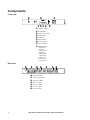
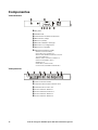
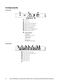
Components
Front view
Rear view
Circuit breaker
LCD Display
ALWAYS ON outlet
DOWN button
UP button
Power button
SETUP button
STATUS button
LED Indicators:
•POWER ON
•LINE OK
•P
ROTECTION
W
ORKING
•WIRING OK
•O
VERLOAD
•DELAYS 1-4
•S
WITCHED
•ALWAYS ON
System Ground
ALWAYS ON outlets
SWITCHED outlet
DELAY 1 outlet
DELAY 2 outlets
DELAY 3 outlet
DELAY 4 outlet
av005a

3APC A/V G-Type Rack Power Filter: Installation
Installation
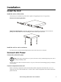
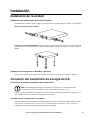
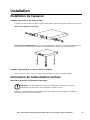
Install the Unit
Install the unit on a flat surface
The unit may be installed on any flat surface capable of supporting at least 27.3 kg (60 lbs).
Remove the mounting brackets.
Attach the stabilizing feet.
Attach the stabilizing feet (included) to the bottom of the unit before
placing it on a flat surface to avoid scratching the surface and to protect the unit.
Install the unit in a rack or enclosure
Use four screws to secure the mounting brackets to the rails in the rack or enclosure.
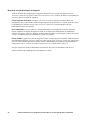
Connect A/C Power
Connect the unit to A/C power
Note: If the unit is connected to A/C power, the unit is actively monitoring input power, but is
operating in Standby mode.
Use the A/C power cord to connect the unit to A/C power. If the unit is functioning properly, the display
will illuminate.
Connect components to the unit
Before connecting components to the unit, determine which components will utilize the ALWAYS ON
outlets, the SWITCHED outlet, and the DELAY outlets. Then, connect components to the outlets on the back
panel of the unit.

APC A/V G-Type Rack Power Filter: Installation4
Always On outlets. The ALWAYS ON outlets supply power to the connected components, even if the
unit is turned off. If A/C power is lost, and then re-applied to the unit, components connected to the
ALWAYS ON outlets will turn on immediately, as power will be supplied to them immediately.
Switched outlet. The SWITCHED outlet supplies power to the connected equipment while the unit is on.
If the unit shuts off, it will not supply power to equipment connected to the
SWITCHED outlet. If A/C
power is lost, and then re-applied to the unit, equipment connected to the
SWITCHED outlet will turn on
immediately.
Delay outlets. The unit has five delayed outlets. When the unit is turned on, power is immediately
applied to the
SWITCHED outlet (power was already being supplied to the ALWAYS ON outlets, even though
the unit was off). Then, power is applied to each of the
DELAYED outlets in sequence, DELAY 1 first,
through
DELAY 4.
When the unit is turned off, power is disconnected from the delayed outlets in reverse order.
Use the display interface to customize the delay times.

5APC A/V G-Type Rack Power Filter: Operation
Operation
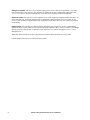
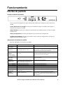
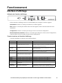
Display Interface
Using the display interface
Use the display interface on the front of the G5BLK to configure and operate the unit.
Power. Push to apply power to the unit or to shut off power to the unit.
Status. Push to display the current status of the unit, including the current input/output voltage.
Setup. Push to scroll through the setup menus.
Up/Down. Push to change values (Setup menu) and browse menu pages (Status menu).
Display interface LEDs
There are eleven LEDs on the display interface.
LED Illuminated Not Illuminated
POWER ON
The unit is supplied with utility
power.
There is no input utility power.
LINE OK
The utility power is within
acceptable range, 92 V to 140 V.
The input voltage from utility power is outside the
acceptable range and the unit has disconnected from
utility power to protect the connected equipment.
PROTECTION
W
ORKING
The unit is protecting all connected
equipment.
The unit is not providing power protection. See
Troubleshooting and contact APC Technical Support
immediately.
WIRING OK
The unit is functioning properly. There is a problem with the building wiring. Contact a
certified electrician.
OVERLOAD
The unit is overloaded. Disconnect
some connected components.
Contact APC Technical Support.
The unit is functioning properly.
DELAY 1
Power is being supplied to DELAY1. Power is not being supplied to DELAY1.
DELAY 2
Power is being supplied to DELAY2. Power is not being supplied to DELAY2.
DELAY 3
Power is being supplied to DELAY3. Power is not being supplied to DELAY3.
D
ELAY 4
Power is being supplied to DELAY4. Power is not being supplied to DELAY4.
SWITCHED
Power is being supplied to the
SWITCHED outlet.
Power is not being supplied to the
SWITCHED outlet.
ALWAYS ON
Power is being supplied to the
ALWAYS ON outlets.
Power is not being supplied to the
ALWAYS ON outlets.
See “Troubleshooting” on page 10 and contact APC
Technical Support immediately.

APC A/V G-Type Rack Power Filter: Operation6
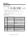
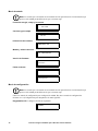
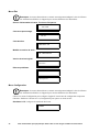
Status menu
Note: The menus shown in this manual are for reference only. Information displayed on the
unit may be different than shown here.
Utility Source, Voltage and Frequency.
Current and Percentage.
Contact Information.
Model and Serial Number.
Firmware version.
Recent Faults.
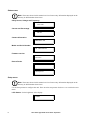
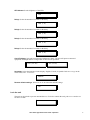
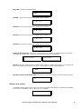
Setup menu
Note: The menus shown in this manual are for reference only. Information displayed on the
unit may be different than shown here.
Use the Setup menus to configure the unit. There are nine setup menus. Push
SETUP to scroll to the next
menu.
LCD dimmer. Set the brightness of the display.
UTILITY SOURCE
120V 60Hz
TOTAL OUTPUT
12A 80%
1-888-8827228
WWW.APCAV.COM
G5 POWER FILTER
SN: AB1234567890
FW REVISION:
860.M1.D
NO FAULT
FAULT CONDITION
Description
DISPLAY DIMMER:
NORMAL

7APC A/V G-Type Rack Power Filter: Operation
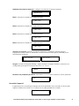
LED dimmer. Set the brightness of the LED.
Delay1. Select the number of seconds for the delay.
Delay2. Select the number of seconds for the delay.
Delay3. Select the number of seconds for the delay.
Delay4. Select the number of seconds for the delay.
Cut-Off Voltage. Select the maximum and minimum voltage. The unit will protect connected
equipment from high and low voltages that are not safe for operation.
Language. Select the language for the display: English, French, or Spanish. Push SETUP to go to the
next screen,
RESET TO DEFAULT.
Restore default settings. Select YES or NO to restore the default settings.
Lock the unit
The unit can be locked to prevent unwanted access. To lock or unlock the unit, push STATUS and DOWN
for three seconds.
LED DIMMER:
DIM1
DELAY 1:
4SEC (1-60)
DELAY 2:
4SEC (1-60)
DELAY 3:
4SEC (1-60)
DELAY 4:
4SEC (1-60)
MAX UPPER VOLT:
140V (132-140)
MIN LOWER VOLT:
92V (92-100)
MENU LANGUAGE:
ENGLISH
RESET TO DEFAULT
YES
G5BLK LOCKED

APC A/V G-Type Rack Power Filter: Operation8
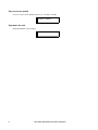
Save screen as default
To save a screen as the default, push STATUS for three seconds.
Shut down the unit
Push and hold the POWER button.
THIS SCREEN IS
SAVED AS DEFAULT
POWERING DOWN

9APC A/V G-Type Rack Power Filter: Configuration
Configuration
Configure the unit
Select a language. Push the SETUP button until the Language menu is displayed. Select English,
French, or Spanish.
Configure the brightness of the display. To alter the brightness of the LCD display screen, push
SETUP one time and select a numerical value, one through seven.
Configure the sequence delay outlets
Configure the delay options so that the DELAY outlets apply power in sequence, instead of all at one time.
Push
SETUP until the delay menu screen appears. Use the UP and DOWN buttons to change the number of
seconds of delay. When finished, push
SETUP again to move to the next delay screen.
View status of the unit
Push the STATUS button until the input source voltage and frequency screen appears.
Push the
STATUS button to display the output current and percentage.
You can also view APC Technical Support contact information, the model and serial number of the unit,
the firmware version, and the last three faults registered by the unit using the
STATUS menus.

APC A/V G-Type Rack Power Filter: Troubleshooting10
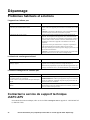
Troubleshooting
Common problems and solutions
The unit will not turn on
The Overload indicator is illuminated
The Wiring OK indicator is not illuminated
Contact APC APV Technical Support
For technical support, go to www.apcav.com or call 1-888-88APCAV (1-888-882-7228).
Probable Cause Solution
There is no input power, or insufficient input power
from the wall outlet.
Use a voltmeter to check the output of the wall outlet. Use a
device that is known to work properly to check the outlet.
Note: The unit will not turn on if the input utility power is out
of the acceptable range.
A circuit breaker has been tripped. Check the building circuit breakers and the unit’s circuit
breaker. If the circuit breaker on the unit has been tripped, the
center post will protrude from the unit. To reset the breaker,
push the center post into the unit. If it trips again, unplug one of
the components plugged into the unit and reset the breaker.
The unit is rated for 15 Amps, however, the National Electric
Code (NEC) dictates that any home circuit should not be
loaded to more than 80% of its rating.
Note: If the breaker is tripped again after trying this solution,
contact APC Technical Support.
Probable Cause Solution
The unit is overloaded. The overload LED is flashing. The Overload LED on the front of the unit will illuminate red if
the unit is overloaded. Reduce the load by disconnecting one or
more components from the back of the unit. When the load is
below 95%, the LED will stop flashing.
Probable Cause Solution
• The wall outlet polarity is reversed.
• The neutral wire is overloaded.
• The earth ground is not connected at the wall outlet.
Contact an electrician to inspect the building wiring.
WARNING: Do not operate the unit if any of these conditions
exist. The unit may not be providing surge protection.
The unit is on, but none of the LEDs are illuminated. Push
UP or DOWN several times. The LEDs should illuminate.
If they do not illuminate, contact APC Technical Support.

11APC A/V G-Type Rack Power Filter: Specifications
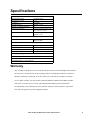
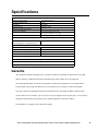
Specifications
Warranty
APC warrants its products to be free from defects in materials and workmanship under normal
use and service for the lifetime of the original purchaser. Its obligation under this warranty is
limited to repairing or replacing, at its sole option, any such defective products. To obtain
service under warranty you must obtain a Returned Material Authorization (RMA) number
from APC or an APC Service Center with transportation charges prepaid and must be
accompanied by a brief description of the problem and proof of date and place of purchase.
This warranty applies only to the original purchaser.
Input/Output
Input/Output Voltage Nominal 120 V
Input/Output Current 15 A
Frequency 50/60 Hz
Receptacle Types NEMA 5-15R
Number of Outlet Receptacles 9
Dimensions (HxWxL) 4.34 cm x 24 cm x 43.5 (1.71
in x 9.45 in 17.13 in)
Power Cord 2.4 m (8 ft.) right angle
NEMA 5-15P
AC Surge Performance
EMI/RFI Filtering 50 db 150 kHz to 1 MHz 40
dB to 30 MHz
Environmental Performance Specifications
Operating temperature 0º – 40ºC (32º – 104ºF)
Storage temperature -15º – 45ºC (5º – 113º F)
Net weight 3.9 kg (8.58 lbs)
Relative Humidity 0–95% non-condensing
Safety Agency Approval
UL1449, UL1363, cCSAus Listed, FCC Part 15 Class B
Contact Information
www.apcav.com or 1-888-88APCAV
Page is loading ...
Page is loading ...
Page is loading ...
Page is loading ...
Page is loading ...
Page is loading ...
Page is loading ...
Page is loading ...
Page is loading ...
Page is loading ...
Page is loading ...
Page is loading ...
Page is loading ...
Page is loading ...
Page is loading ...
Page is loading ...
Page is loading ...
Page is loading ...
Page is loading ...
Page is loading ...
Page is loading ...
Page is loading ...
Page is loading ...
Page is loading ...
Page is loading ...
Page is loading ...

3/2010990-3367B
APC Worldwide Customer Support
Customer support for this or any other APC product is available at no charge in any of the following ways:
• Visit the APC Web site to access documents in the APC Knowledge Base and to submit customer
support requests.
– www.apc.com (Corporate Headquarters)
Connect to localized APC Web sites for specific countries, each of which provides customer support
information.
– www.apcav.com
APC Audio/Visual Technical Support
– www.apc.com/support/
Global support searching APC Knowledge Base and using e-support.
• Contact the
APC Customer Support Center by telephone or e-mail.
– Local, country-specific centers: go to www.apc.com/support/contact for contact information.
For information on how to obtain local customer support, contact the APC representative or other distributors
from whom you purchased your APC product.
Entire contents copyright 2010 American Power Conversion Corporation. All rights reserved. Reproduction
in whole or in part without permission is prohibited. APC, the APC logo, and the APC AV logo are
trademarks of American Power Conversion Corporation. All other trademarks, product names, and corporate
names are the property of their respective owners and are used for informational purposes only.
-
 1
1
-
 2
2
-
 3
3
-
 4
4
-
 5
5
-
 6
6
-
 7
7
-
 8
8
-
 9
9
-
 10
10
-
 11
11
-
 12
12
-
 13
13
-
 14
14
-
 15
15
-
 16
16
-
 17
17
-
 18
18
-
 19
19
-
 20
20
-
 21
21
-
 22
22
-
 23
23
-
 24
24
-
 25
25
-
 26
26
-
 27
27
-
 28
28
-
 29
29
-
 30
30
-
 31
31
-
 32
32
-
 33
33
-
 34
34
-
 35
35
-
 36
36
-
 37
37
-
 38
38
-
 39
39
-
 40
40
-
 41
41
-
 42
42


APC AV G-Type Rack Power Filter 120V 15A User guide
- Category
- Surge protectors
- Type
- User guide
- This manual is also suitable for
Ask a question and I''ll find the answer in the document
Finding information in a document is now easier with AI
in other languages
Related papers
-
APC AR8125 Installation guide
-
Schneider Electric G50B-20A2 User manual
-
-
-
-
APC J25B User manual
-
-
-
Schneider Electric UPS PDU Replacement Panel User guide
-


