
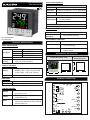
PID CONTROLLER
PID 2303-1C-M1
PV = Process value
SV = Set value
INPUT SPECIFICATION:
Input Types
Resolution
Indication
Accuracy
Input Range
0 to 400°CJ
K
J,K = 1°C
±1% of FSD ± 1°C
(FSD:- full scale deflection)
DISPLAY AND KEYS:
CONTROL METHOD:
DIMENSION:
Display
Heating
Size (mm)
Cooling
Alarm
Panel Cutout
Upper: 3 digit, 7 seg 0.70” white LED
1) PID control with Auto-Tuning
Middle: 3 digit, 7 seg, 0.39” green LED
2) ON-OFF control
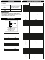
72 (H) x 72 (W) x 85 (D) mm
68 (H) x 68 (W) mm
TECHNICAL SPECIFICATION
0 to 500°C
Lower: 3 digit, 7 seg, 0.33” red LED
POWER SUPPLY:
ENVIRONMENT CONDITION:
Power Consuption
(VA Rating)
Relative Humidity
Protection Level
Supply Voltage
Operating Temp.
100 to 270V AC, 50-60Hz
0°C to 55°C
UP to 95% RH
(non-condensing)
IP-65 (Front side) As per IS/IEC
60529 : 2001
Approx 6VA @ 230V AC
TERMINAL CONNECTION
MECHANICAL INSTALLATION
1 CT 0.0 to 30.0 A
1) BL.TP ( Blower Time Proportion)
Heater break alarm, Cold start, High,
Absolute low, Inband, Absolute outband,
OFF, Outband, Low
2) ON-OFF control
72
85
68
68
3
72
Outline Dimension (mm) Panel Cutout
Dimension (mm)
1
2
8
9
10
11
12
13
14
L
N
!
H1
RELAY-3
RELAY-1
NO
NO
CT
COM.
D+ D-
RELAY-2
-
+
TC
100
270V AC
~
50/60 Hz
6VA
15
18
16
19
17
20
3
4
5
6
7
NO
S.S.R
-
+
C
NC
C
C
www.multispanindia.com
Made in India
Keys SET, INC, DEC, ENT
OUTPUT SPECIFICATION:
Relays
Output Signal
Relay Type
Rating
3 Nos
24V DC, 30mA DC
(On-Off condition)
Relay 1 parallel to SSR
RS-485 Modbus Communication
st nd rd
1 Relay 1C/O (NO-C-NC) , 2 & 3 Relay (NO-C)
5A,230V AC/28V DC
Relay Output
SSR Drive Output
MODBUS
PID-2303-1C-M1

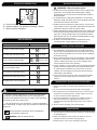
KEY OPERATION
Read complete instructions prior to installation
and operation of the unit.
WARNING : Risk of electric shock.
SAFETY PRECAUTION
!
All safety related codifications, symbols and instructions
that appear in this operating manual or on the equipment
must be strictly followed to ensure the safety of the operating
personnel as well as the instrument.
If all the equipment is not handled in a manner specified by
the manufacturer, it might impair the protection provided by the
equipment.
WARNING GUIDELINES
WARNING : Risk of electric shock.
1. To prevent the risk of electric shock power, supply to the
equipment must be kept OFF while doing the wiring
arrangement. Do not touch the terminals while power is
being supplied.
2. To reduce electro magnetic interference, use wire with
adequate rating and twists of the same of equal size shall
be made with shortest connection.
3. Cable used for connection to power source, must have a
cross section of 1mm or greater. These wires should have
insulations capacity made of at least 1.5kV.
4. When extending the thermocouple lead wires, always use
thermocouple compensation wires for wiring for the RTD
type, use a wiring material with a small lead resistance
(5 max per line) and no resistance differentials among
three wires should be present.
5. A better anti-noise effect can be expected by using
standard power supply cable for the instrument.
Ω
INSTALLATION GUIDELINES
1. This equipment, being built-in-type, normally becomes a
part of main control panel and in such case the terminals
do not remain accessible to the end user after installation
and internal wiring.
2. Do not allow pieces of metal, wire clippings, or fine metallic
fillings from installation to enter the product or else it may
lead to a safety hazard that may in turn endanger life or
cause electrical shock to the operator.
3. Circuit breaker or mains switch must be installed between
power source and supply terminal to facilitate power ‘ON’
or ‘OFF’ function. However this mains switch or circuit
breaker must be installed at convenient place normally
accessible to the operator.
4. Use and store the instrument within the specified ambient
temperature and humidity ranges as mentioned in this
manual.
MECHANICAL INSTALLATION GUIDELINES
1. Prepare the panel cutout with proper dimensions as shown
above.
2. Fit the unit into the panel with the help of clamp given.
3. The equipment in its installed state must not come in close
proximity to any heating source, caustic vapors, oil steam,
or other unwanted process byproducts.
4. Use the specified size of crimp terminal (M3.5 screws) to
wire the terminal block. Tightening the screws on the
terminal block using the tightening torque of the range of
1.2 N.m.
5. Do not connect anything to unused terminals.
MAINTENANCE
1. The equipment should be cleaned regularly to avoid blockage
of ventilating parts.
2. Clean the equipment with a clean soft cloth. Do not use
isopropyl alcohol or any other cleaning agent.
3. Fusible resistor must not be replaced by operator.
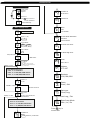
To enter in parameter setting
For start/stop PID auto tuning Press for 6 sec
Press 3 sec
+
To go in factory setting mode
PRESS KEYFUNCTION
OPERATOR MODE
PARAMETER SETTING MODE
To set parameter value
To increment parameter value.
To decrement parameter value.
Set parameter to be save & exit.
STATUS LED DESCRIPTION
A - Control output 1 indication (Heating)
B - Control output 2 indication (Cooling / Alarm)
C - Alarm output indication
Press for 4 sec
A
B
C
1
H
PV
SV
TUNE
A
~
°c
1
OU T
2
OU T
3
OU T

ERROR
OPN
SRE
MEANING
When an error has occurred the display indicates error codes
as given below.
ERROR DISPLAY
FACTORY SETTING
PARAMETER MESSAGE DESCRIPTION
FACTORY SETTING
PARAMETER
IT
CT
Alarm Time R3
Offset
PB
DT
MR
Hysteresis1
Hysteresis 2
Alarm Time R2
Hysteresis 3
VALUES
300
15 Sec
20.0°C
75
0°C
5 Sec
0°C
3°C
1°C
5 Sec
3°C
SR.
2
4
13
13
1
3
5
9
10
11
12
Press + key
for 3 sec
CORRECTIVE ACTION:
Check the sensor and the input wiring. If problem still exists,
replace the sensor. And still if problem is not solved yet by the
user, then please contact company person
yes
: Press key to apply factory set
values as shown in table.
: Press key to escape
from factory setting.
ENT
ENT
Sensor is not connected or
Sensor connection is reversed
Over range condition or
sensor break
no
no
R2M
ALM
HBA
HBA
HbI
HIG
LOW
H
ON
DT
ABL
OTB
OFF
CT
INB
PB
MR
CS
IT
Blower TP Action
Hysterisis 2
Absolute Outband Alarm
Relay 3 Mode
Time
Alarm
Cold Start Alarm
Heater
ON-OFF Action
PID Action
Heater Break Alarm
Heater Break Alarm Set Point
High Alarm
Low
ON
Absolute Low Alarm
Outband
OFF
In Band Alarm
Proportional Band for PID Action
Integral Time for PID Action
Derivative Time for PID Action
Cycle Time for PID Action
Manual Reset for PID Action
ONF
PID
Relay 1 Mode
J
J
Hy1 Hysterisis 1
Relay 2 Mode
HET
COL
Heating
Cooling
K
INP Input
B.TP
Hy2
ABO
R3M
TIM
C PB
C ON
Parameter Description
Heater Break Indication Set Point
C OF
par
pas
Parameter
Password
Hy3 Hysterisis 3
RLT Relative
IND Individual
C-PB
C-ON
C-OF
4.0
1°C
48
6
7
8
Cooling Proportional Band
Cooling ON
Cooling OFF
St1
St2
ST2LOW
St3
ST2HIGH
ST3LOW
Set 2 High
Set 3 Low
ST3HIGH Set 3 High
OFS Offset
OPM Output Mode
Set 1
Set 2
Set 2 Low
Set 3Set 3
Both/Relay/SSR
btH/rLY/SSR
1
H
PV
SV
H2
H3 A
~
°c
1
OUT
2
OUT
3
OUT

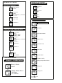
Auto Tuning:-
The Auto-tuning function automatically computes
and sets the Proportional band (Pb) , Integral time (It),
Derivative time (dt), and cycle time as per process
characteristics.
Tuning LED will turn “ON” during Auto-Tuning
If the power goes off before auto-tuning is completed,
auto-tuning will be restarted at next power ON.
PARAMETER RANGE
Parameter Range For J, K
PB 0.0°C to 999.9°C
IT
0 to 9999
DT 0 to 9999
CT 4 sec to 99 sec
MR -9 to +9
2.0°C to 25.0°C
Hysteresis-1 1°C To 100°C
0.0 to 60.0A
5 to 200
Hysteresis-3
0 Sec to 99 Sec
0 Sec to 99 Sec
1°C to 50°C
1°C to 100°C
-20°C to 20°C
Hysteresis-2
1°C to 20°C
C.PB
C.ON
C.OF
Alarm Time R2
Alarm Time R3
Set 2
Offset
HBAL/HBI H
WORKING
2) Control Mode ON/OFF: Relay turns ON (and remains ON) when
PV < SV. Relay turns OFF when PV > SV. After this there may be
overshoot depending on the thermal inertia of the machine.
When the PV < SV Minus HYS, Relay turns ON and heating is
resumed.
1) Control Mode PID: Relay turning ON/OFF according to heat
requirement of the machine.
R1-Heating
R2-Cooling
1) Cooling Time proportional Control action: Relay turns ON/OFF
as per et Cycle timeand difference between PV and cooling SV.
2) Cooling ON/OFF control action: Relay is initially OFF. When
PV > SV, Relay turns ON and when PV < SV Minus HYS relay
turns OFF.
Set 2
Set 3
Set 2 Low
Set 3 Low
Set 2 High
Set 3 High
1°C to 50°C
R2MD = CS
R3MD = CS
R2MD = HIG/
LOW/ABL
R3MD = HIG/
LOW/ABL
S2MD = RLT
S3MD = RLT
S2MD = IND
S3MD = IND
S2MD = RLT
S3MD = RLT
S2MD = IND
S3MD = IND
-50 to 0
-50 to 0
0 to set 100
0 to set 100
-50 to +50
-50 to +50
SLL to SHL
SLL to SHL
SLL To SET2 HIGH
SLL To SET3 HIGH
SET2 LOW To SHL
SET3 LOW To SHL

Ampere
Set Point-1
Press key for 4 sec to
enter Password
SET
Process Value
Press key
ENT
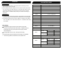
Set Point Setting
Basic configuration
Set Value
Password Message
If PID Select
h
Input ( J / K )
ONF
ONF
Case 1 :- If CS Select
Case 2 :- If HIG,ABL,LOW Select
FOR RELAY-2 Alarms
Case 3 :- If INB,ABO,OTB Select
Relay 1 Mode
Relay 2 Mode
Coolig / Alarm
(Blower TP Action/ON-OFF/
High Alarm/ABL/INB/ABO/OFF
/OTB/LOW/CS)
Set Point 2
1 to 50
If On/Off Select
If R2MD = ON-OFF
Enter Password 73
Output Mode
SSR RLY
(Both/S.S.R/Relay)
If Blower TP Select
1
H
PV
SV
A
~
°c
1
OUT
2
OUT
3
OUT
If Relay 2 OFF
Hysterisis 3
Set Point 3
Alarm
time
0 to 99 Sec
Set Point Low Limit
Set Point High Limit
Offset
-20 to 20°C
-50 To 50°C
Heater Break Indication
Set Point
0.0 TO 30.0A
Press key to
save & exit
ENT
Address
Baudrate
Parety
Data type
Bytes Swap Mode
If Select Long / Flot
1 TO 127
/192/384/480
/Even / Odd
/Float/Long
/Beb / Le / Be
Set Point 3
Mode
Relative / Individual
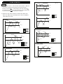
Case 4 :- If HBA Select
Case 5 :- If CS Select
Case 7 :- If INB,ABO,OTB Select
Case 6 :- If HIG,ABL,LOW Select
Relay 3 Mode
Alarm
High Alarm,ABL,INB,ABO,OFF,
OTB,LOW,HBA,CS
IND
If Relay 3 OFF
PARAMETER SETTING

Relay 3 Mode
Heater Break Alarm
Set Point
Case 4 :- If HBA Select
Hysterisis 2
Hysterisis 2
Relay 2 Mode
Relay 2 Mode
Set Point 2
Set Point 2
Set Point 2
Set Point 2
Case 1,5 :- If CS Select
Case 2,6 :- If HIG / ABL/LOW; Select
Alarm
aBL
Alarm
Alarm
Alarm
Mode
Mode
Relative / Individual
Relative / Individual
time
0 TO 99 Sec
/
0 To -50°C
-50 To 50°C
0.0 TO 30.0A
IND
IND
LOW
/
FOR RELAY-3 Alarms
FOR RELAY-2 & 3 Alarms
FOR RELAY-2 & 3 Alarms
Case 3 & 7 :- INB, ABO,OTB
Set Point 2
Low
Set Point 2
High
Alarm
time
0 TO 99 Sec
FOR RELAY- 2 & 3 Alarms
Control Parameter
Press key to
save & exit
ENT
Proportional Band
PID Action
Integral Time
Derivative Time
Cycle Time
Manual Reset
Enter Password 37
(If R2MD = BL.TP)
Cooling Proportional Band
Cooling ON
Cooling OFF

ALARM OPERATION
Alarms
1) Heater Break alarm: - If the current of the Heater < AMP SV
(unhealthy condition) then Relay turns ON and Upper
Display will show , middle display will blink showing . hbr h
To manually turn off Relay, press ENT key 4 sec. Display will
continue showing till the fault is rectified.hbr
2) Cold start (CS) alarm: Relay is initially OFF. When PV >
Alarm SV, Relay turns ON. When PV < Alarm SV MINUS
HYS, Relay turns OFF.
ABSOLUTE OUTBAND ALARM
RLY-ON
RLY-ON
RLY-ON
RLY-OFF
RLY-ON
RLY-OFF
RLY-OFF
RLY-OFF
RLY-OFF
High
High
Low
Low
ALARM:
INBAND ALARM
ABSOLUTE LOW ALARM
RLY-OFF
RLY-OFF
RLY-ON RLY-ON
RLY-ON RLY-ON
RLY-OFF
RLY-ON
RLY-ON
RLY-ON
RLY-ON
RLY-OFF
RLY-OFF
RLY-OFF
S.V
High
SET
HYST
Low
HYST
High : 125
Low : 75
High : 125
Low : 75
LOW ALARM:
RLY-OFF
RLY-ON
RLY-ON
RLY-ON
RLY-ON
RLY-OFF
RLY-OFF
HYST
S.V
OUTBAND ALARM
RLY-ON
RLY-ON
RLY-ON
RLY-OFF
RLY-OFF
High S.P
Low S.P
High : 125
Low : 75

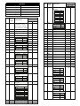
MODBUS
Slave Address :
Parity :
Read Function Register :
Write Function Register :
Baudrate :
Datatype :
1 to 127
None,Even,Odd
0x03 and 0x04
4800,9600,19200,38400 bps
Sign integer, Float
0x06 and 0x10
Note :- When Parameter 1111 = no available
Access
Type
Access
Type
Parameter
Parameter
Register
Register
Data Type
Data Type
Integer
Integer
Float
Float
R Process Value 0 0
Sr.No
Sr.No
1
Initial Value : 32101
Sensor Open : 32102
Sensor Reverse : 32103
R H1 Current 1 2
2
R N/A
3
R N/A
4
R Total Current 4 8
5
2
N/A
N/A
28
4
N/A
N/A
56
3
29
6
58
R H1 5
6
R
7
R
8
10
R R1,R2 & R3 Status 8
9
R
10
R
11
9
10
16
18
20
R PID Percentage
12
11 22
R/W Auto Tune
13
12 24
R/W Heater
14
13 26
R/W Set 1
15
14 28
R/W Input
16
15 30
R/W Relay1 Mode
(Heating)
17
16 32
R/W HYS 1
18
1 to 100
17 34
R/W Relay2 Mode
(Cooling)
19
Absolute Outband Alarm
OFF
High Alarm
INB
19200
ODD
Float
SSR
CS Alarm
LOW
Blower TP
ABL
9600
EVEN
Long
Relay
OFF
OTB
In-Band Alarm
ABO
38400
Outband Alarm
HBA
Low Alarm
CS
Absolute Low Alarm
18 36
R/W Set 2
20
19 38
R/W HYS 2
21
20 40
R/W
22
21 42
Relay3 Mode
(Alarming)
R/W Set 3 Mode
23
22 44
R/W Set 3
24
23 46
R/W Set 3 Low
25
24 48
R/W Set 3 High
26
25 50
R/W HYS 3
27
26 52
R/W HBAL/HBI H1
28
27 54
R/W Alarm Time
29
R/W SLL
30
R/W SHL
31
30 60
N/A
N/A
R/W Offset
32
31 62
R/W PB
33
32 64
R/W IT
34
33 66
35
34 68
36
35 70
R/W
R/W
R/W DT
R/W CT
R/W MR
37
36 72
R/W C.PB
38
37 74
R/W C.ON
39
38 76
R/W C.OFF
40
39 78
R/W Address
41
40 80
R/W Baudrate
42
41 82
R/W Parity
43
42 84
44
43 86
44 88
45
R/W Data Type 45 90
46
R/W Output Selection 46 92
47
Break
ON
ON
Relative
ON
ON-OFF
K
Normal
OFF
OFF
Individual
OFF
PID
ON-0FF
HIGH
4800
NONE
Integer
Both
J
Value
Value
Value
Value
Value
Value
Value
Value
Value
Value
Value
Value
Value
1
1
1
1
1
1
1
1
1
1
1
1
3
3
3
5
5
7
7
9
1
0
0
0
0
0
0
0
0
0
0
0
0
2
2
2
2
2
2
4
4
6
6
8
8
0
Selection
Selection
Selection
Selection
Selection
Selection
Selection
Selection
Selection
Selection
Selection
Selection
Selection

Access
Type Parameter
Register
Data Type
Integer Float
Sr.No
R/W Set 2 Mode
49
48 96
49 98
R/W
R/W
Set 2 Low
Set 2 Alarm Time
50
52
50
52
100
104
R/W
R/W
Set 2 High
Fectory Reset
51
54
51 102
R/W Bytes Swap Mode
(Only select for
Float & Long)
47 94
48
NA NA
53
53 106
Relative
Individual
Little endian
Big endian
Value
Value
1
1
0
0
2
3
Selection
Selection
Little-endian byte Swap
Big-endian byte Swap
-
 1
1
-
 2
2
-
 3
3
-
 4
4
-
 5
5
-
 6
6
-
 7
7
-
 8
8
-
 9
9


Ask a question and I''ll find the answer in the document
Finding information in a document is now easier with AI
Related papers
-
MULTISPAN PID-2303-3C-M1 Owner's manual
-
-
-
-
-
-
-
-
-
Other documents
-
HANYOUNG NUX VX User manual
-
-
Omega CN9600 Series Owner's manual
-
-
Autonics TCN4S User manual
-
-
-
Autonics TC Series TC4Y-N4R Single Display PID Temperature Controllers User manual
-
HANYOUNG NUX AX SERIES User manual
-