Hikoki DH 24PC2 User manual
- Category
- Rotary hammers
- Type
- User manual
This manual is also suitable for

Rotary Hammer
Martillo perforador
DH 24PC2
405
Code No. C99132431 N
Printed in Japan
1
Hitachi Koki Co., Ltd.
HANDLING INSTRUCTIONS
INSTRUCCIONES DE MANEJO
Read through carefully and understand these instructions before use.
Leer cuidadosamente y comprender estas instrucciones antes del uso.
1
2
4
6
8
3
5
7
1
2
3
4
4
5
6
8
9
9
8

3 32
English Español
1
2
3
4
5
6
7
8
9
0
A
B
C
D
E
F
G
H
I
J
K
L
M
N
O
P
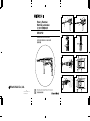
Drill bit
Part of SDS-plus shank
Front cap
Grip
Dust cup
Dust collector (B)
Push button
Change lever
Push button
Drill chuck
Chuck adapter
Chuck adapter (D)
Bit
Socket
Side handle
Depth gauge
Mounting hole
Tape shank adapter
Cotter
Rest
Core bit
Core bit shank
Thread
Center pin
Guide plate
Core bit tip
Broca
Parte delSDS más vástago
Cubierta frontal
Sujetador
Capa de polvo
Colector de polvo (B)
Tecla
Palanquita selectora
Tecla
Portabrocas
Adaptador del portabrocas
Adaptador (D) del portabrocas
Broca
Cubo
Mango lateral
Calibre de profundidad
Agujero de montaje
Adaptador de la espiga ahusada
Chaveta
Apoyo
Barrena tubular
Espiga de la barrena tubular
Rosca
Pasador central
Placa guía
Punta de barrena tubular
2
A B C D
1 306-345 1
2 306-340 1
3 322-809 1
4 322-810 1
5 322-811 1
6 322-812 1
7 984-118 1
8 939-547 1
9 301-654 4 D5×35
10 323-178 1 “44”
11
––––––– 1
12 322-789 1
13 317-223 1
14 323-179 1
15 878-885 1 S-18
16 317-238 2
17 307-688 1
18 322-815 1
19 323-232 1
20 690-4DD 1 6904DDPS2L
21 322-819 1
22 322-813 1
23 959-156 1 D7.0
24 323-184 1
25 323-185 1
26 317-233 1
27 317-234 1
28 317-235 1
29 322-803 1
30 944-486 1 1AP-20
31 322-804 1
32 322-802 1
33 322-805 1
34 322-808 1
35 322-806 1
36 322-807 1
37 322-801 1
38 322-834 1 I.D. 16
39 322-800 1
40 322-793 1 I.D. 66.5
41 322-792 1
42 322-798 1
43 322-799 2
44
––––––– 1
45 318-522 1
46 323-181 1
47 323-182 1
48 323-183 1
49 323-180 1
50 306-990 1
51 322-797 1
52 301-663 1
53 626-VVM 1 626VVC2PS2L
54 322-816 1
55 876-796 1 P-22
56 322-818 1
57 608-DDM 1 608DDC2PS2L
58 982-631 2
59 1 360-648U 1 110V-120V “60-62”
59 2 360-648E 1 220V-230V
59 3 360-648F 1 240V
A B C D
60 322-791 1
61 981-421 2 D4×55
62 1 340-581C 1 110V-120V
62 2 340-581E 1 220V-230V
62 3 340-581F 1 240V
63 608-VVM 1 608VVC2PS2L
64 322-832 1
65
––––––– 1
66 322-790 1
67
––––––– 1
68 999-088 2
69 308-536 2
70 306-945 4 D3×10
71 322-838 2
72 1 322-827 1 “NZL, AUS, GBR(230V),
FIN, SUI, ESP, AUT”
72 2 322-828 1 “GBR(110V)”
72 3 322-826 1
72 4 322-821 1 “VEN”
73 1 322-830 1 “NZL, AUS, GBR(230V),
FIN, SUI, ESP, AUT”
73 2 322-831 1 “GBR(110V)”
73 3 322-829 1
73 4 322-822 1 “VEN”
74 322-823 2
75 1 322-825 1
75 2 322-820 1 “VEN, GBR(110V)”
76 930-039 1
77 981-373 2
78 1 953-327 1 D8.8
78 2 938-051 1 D10.1
79
––––––– 1
80 937-631 1
81 984-750 2 D4×16
82 301-653 2 D4×20
83 322-833 1
501 323-130 1
502 303-659 1
503 303-709 1
9
10
C
D
B
H
J
12
11
I
3
4
13
15
14
E
F
G
1
H
3
4
12
11
8
9
9
8
4
16
17
20
18 19
L
K
L
M
O
N
K
P
21

English
4
GENERAL OPERATIONAL PRECAUTIONS
WARNING! When using electric tools, basic safety
precautions should always be followed to reduce the
risk of fire, electric shock and personal injury, including
the following.
Read all these instructions before operating this product
and save these instructions.
For safe operations:
1. Keep work area clean. Cluttered areas and benches
invite injuries.
2. Consider work area environment. Do not expose
power tools to rain. Do not use power tools in
damp or wet locations. Keep work area well lit.
Do not use power tools where there is risk to cause
fire or explosion.
3. Guard against electric shock. Avoid body contact
with earthed or grounded surfaces (e.g. pipes,
radiators, ranges, refrigerators).
4. Keep children and infirm persons away. Do not let
visitors touch the tool or extension cord. All visitors
should be kept away from work area.
5. Store idle tools. When not in use, tools should be
stored in a dry, high or locked up place, out of reach
of children and infirm persons.
6. Do not force the tool. It will do the job better and
safer at the rate for which it was intended.
7. Use the right tool. Do not force small tools or
attachments to do the job of a heavy duty tool. Do
not use tools for purposes not intended; for example,
do not use circular saw to cut tree limbs or logs.
8. Dress properly. Do not wear loose clothing or
jewelry, they can be caught in moving parts. Rubber
gloves and non-skid footwear are recommended
when working outdoors. Wear protecting hair
covering to contain long hair.
9. Use eye protection. Also use face or dust mask if
the cutting operation is dusty.
10. Connect dust extraction equipment.
If devices are provided for the connection of dust
extraction and collection facilities ensure these are
connected and properly used.
11. Do not abuse the cord. Never carry the tool by the
cord or yank it to disconnect it from the receptacle.
Keep the cord away from heat, oil and sharp edges.
12. Secure work. Use clamps or a vise to hold the work.
It is safer than using your hand and it frees both
hands to operate tool.
13. Do not overreach. Keep proper footing and balance
at all times.
14. Maintain tools with care. Keep cutting tools sharp
and clean for better and safer performance. Follow
instructions for lubrication and changing
accessories. Inspect tool cords periodically and if
damaged, have it repaired by authorized service
center. Inspect extension cords periodically and
replace, if damaged. Keep handles dry, clean, and
free from oil and grease.
15. Disconnect tools. When not in use, before servicing,
and when changing accessories such as blades,
bits and cutters.
16. Remove adjusting keys and wrenches. Form the
habit of checking to see that keys and adjusting
wrenches are removed from the tool before turning
it on.
17. Avoid unintentional starting. Do not carry a plugged-
in tool with a finger on the switch. Ensure switch is
off when plugging in.
18. Use outdoor extension leads. When tool is used
outdoors, use only extension cords intended for
outdoor use.
19. Stay alert. Watch what you are doing. Use common
sense. Do not operate tool when you are tired.
20. Check damaged parts. Before further use of the
tool, a guard or other part that is damaged should
be carefully checked to determine that it will operate
properly and perform its intended function. Check
for alignment of moving parts, free running of
moving parts, breakage of parts, mounting and any
other conditions that may affect its operation. A
guard or other part that is damaged should be
properly repaired or replaced by an authorized
service center unless otherwise indicated in this
handling instructions. Have defective switches
replaced by an authorized service center. Do not
use the tool if the switch does not turn it on and off.
21. Warning
The use of any accessory or attachment, other than
those recommended in this handling instructions,
may present a risk of personal injury.
22. Have your tool repaired by a qualified person.
This electric tool is in accordance with the relevant
safety requirements. Repairs should only be carried
out by qualified persons using original spare parts.
Otherwise this may result in considerable danger
to the user.
PRECAUTIONS ON USING ROTARY HAMMER
1. Wear earplugs to protect your ears during operation.
2. Do not touch the bit during or immediately after
operation. The bit becomes very hot during
operation and could cause serious burns.
3. Before starting to break, chip or drill into a wall,
floor or ceiling, thoroughly confirm that such items
as electric cables or conduits are not buried inside.
4. Always hold the body handle and side handle of
the power tool firmly. Otherwise the counterforce
produced may result in inaccurate and even
dangerous operation.

English
5
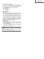
OPTIONAL ACCESSORIES (sold separately)
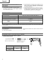
1. Drilling anchor holes (rotation + hammering)
䡬 Drill bit (Slender shaft)
䡬 Drill bit (Taper shank) and taper shank adapter
Drill bit (slender shaft)
Outer diameter Effective length Overall length
3.4 mm
45 mm 90 mm
3.5 mm
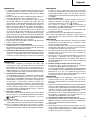
SPECIFICATIONS
Voltage (by areas)* (110V, 115V, 120V, 127V, 220V, 230V, 240V)
Power Input 720W*
No-load speed 0 – 1150/min.
Full-load impact rate 0 – 4600/min.
Capacity: concrete 3.4 – 24 mm
steel 13 mm
wood 32 mm
Weight (without cord and side handle) 2.5 kg
* Be sure to check the nameplate on product as it is subject to change by areas.
STANDARD ACCESSORIES
(1) Plastic case .................................................................. 1
(2) Side handle ................................................................. 1
(3) Depth gauge ............................................................... 1
Standard accessories are subject to change without
notice.
Adapter for slender shaft
(SDS-plus shank)
Drill bit (Slender shaft)
Drill bit (Taper shank)
Taper shank adapter
(SDS-plus shank)
Cotter
Outer diameter
11.0 mm
12.3 mm
12.7 mm
14.3 mm
14.5 mm
17.5 mm
21.5 mm
Taper mode Applicable drill bit
Morse taper (No.1) Drill bit (taper shank) 11.0 ~ 17.5 mm
Morse taper (No.2) Drill bit (taper shank) 21.5 mm
A-taper Taper shank adapter formed A-taper or B-taper
is provided as an optional accessory, but the
B-taper
drill bit for it is not provided.

English
6
( )
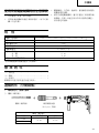
Straight shank bit
for impact drill
䡬 13 mm rotary hammer chuck
For drilling operations when using a straight shank bit for impact drilling with a rotary hammer.
13 mm rotary hammer chuck
(SDS-plus shank)
Chuck wrench
䡬 Anchor setting adapter (for manual hammer)
Anchor setting adapter
(for manual Hammer)
Anchor setting adapter (SDS-plus shank)
(for rotary hammer)
Overall length: 160, 260 mm
Anchor size
W1/4”
W5/16”
W3/8”
Anchor size
W1/4”
W5/16”
W3/8”
W1/2”
W5/8”
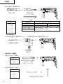
3. Large hole boring (rotation + hammering)
䡬 Center pin, core bit, core bit shank and guide plate.
(Guide plate) Center pin Core bit Core bit shank
(SDS-plus shank)
Center pin Core bit (outer diameter) Core bit shank
–
25 mm
29 mm
(A)
32 mm Core bit shank (A)
Center pin (A) 35 mm
38 mm
45 mm
Center pin (B) (B)
50 mm
Core bit shank (B)
Do not use core bits with with guide plate
outer diameter of 25 mm (The guide plate is not equipped with core bits
and 29 mm. with outer diameter of 25 mm and 29 mm.)
2. Anchor setting (hammering only)
䡬 Anchor setting adapter (for rotary hammer)

English
7
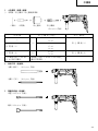
4. Crushing operation (Hammering only)
Bull point (Round type) (SDS-plus shank)
Bull point (Square type) (SDS-plus shank)
5. Groove digging and edging (Hammering only)
Cold chisel (SDS-plus shank)
Cutter (SDS-plus shank)
6. Grooving (Hammering only)
Grooving chisel (SDS-plus shank)
7. Bolt placing operation with Chemical Anchor. (rotation + hammering)
(SDS-plus shank)
12.7 mm Chemical Anchor Adapter
19 mm Chemical Anchor Adapter
Standard socket
on the market
( )

English
8
9. Drilling holes (rotation only)
Chuck adapter (D)
(SDS-plus shank)
Chuck wrench
䡬 13 mm drill chuck ass’y (includes chuck wrench) and chuck (for drilling in steel or wood).
10. Driving Screws (rotation only)
Chuck adapter (D)
(SDS-plus shank)
Bit No. Screw Size Length
No. 2 3 – 5 mm 25 mm
No. 3 6 – 8 mm 25 mm
11. Dust cup, Dust collector (B)
Optional accessories are subject to change without notice.
Dust cup
Dust collector (B)
12. Hammer grease A
500 g (in a can)
70 g (in a green tube)
30 g (in a green tube)
Bit No.
Drill chuck (13 VLD-D)
8. Drilling holes and driving screws (rotation only)
䡬 Drill chuck, chuck adapter (G), special screw and chuck wrench
Chuck adapter (G)
(SDS-plus shank)
Chuck wrench
Drill chuck (13 VLRB-D)Special screw

English
9
APPLICATIONS
Rotation and hammering function
䡬 Drilling anchor holes
䡬 Drilling holes in concrete
䡬 Drilling holes in tile
Rotation only function
䡬 Drilling in steel or wood
(with optional accessories)
䡬 Tightening machine screws, wood screws
(with optional accessories)
Hammering only function
䡬 Light-duty chiselling of concrete, groove digging and
edging.
PRIOR TO OPERATION
1. Power source
Ensure that the power source to be utilized conforms
to the power requirements specified on the product
nameplate.
2. Power switch
Ensure that the power switch is in the OFF position. If
the plug is connected to a power receptacle while the
power switch is in the ON position, the power tool
will start operating immediately, which could cause a
serious accident.
3. Extension cord
When the work area is removed from the power
source, use an extension cord of sufficient thickness
and rated capacity. The extension cord should be
kept as short as practicable.
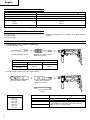
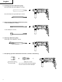
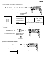
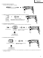
4. Mounting the drill bit (Fig. 1)
CAUTION:
To prevent accidents, make sure to turn the switch
off and disconnect the plug from the receptacle.
NOTE:
When using tools such as bull points, drill bits, etc.,
make sure to use the genuine parts designated by
our company.
(1) Clean the shank portion of the drill bit.
(2) Insert the drill bit in a twisting manner into the tool
holder until it latches itself. (Fig. 1)
(3) Check the latching by pulling on the drill bit.
(4) To remove the drill bit, fully pull the grip in the
direction of the arrow and pull out the drill bit. (Fig. 2)
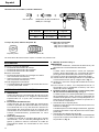
5. Installation of dust cup or dust collector (B)
(Optional accessories) (Fig. 3, Fig. 4)
When using a rotary hammer for upward drilling
operations attach a dust cup or dust collector (B) to
collect dust or particles for easy operation.
䡬 Installing the dust cup
Use the dust cup by attaching to the drill bit as shown
in Fig. 3.
When using a bit which has big diameter, enlarge the
center hole of the dust cup with this rotary hammer.
䡬 Installing dust collector (B)
When using dust collector (B), insert dust collector
(B) from the tip of the bit by aligning it to the groove
on the grip. (Fig. 4)
CAUTION:
䡬 The dust cup and dust collector (B) are for exclusive
use of concrete drilling work. Do not use them for
wood or metal drilling work.
䡬 Insert dust collector (B) completely into the chuck
part of the main unit.
䡬 When turning the rotary hammer on while dust
collector (B) is detached from a concrete surface,
dust collector (B) will rotate together with the drill bit.
Make sure to turn on the switch after pressing the
dust cup on the concrete surface. (When using dust
collector (B) attached to a drill bit that has more than
190 mm of overall length, dust collector (B) cannot
touch the concrete surface and will rotate. Therefore
please use dust collector (B) by attaching to drill bits
which have 166 mm, 160 mm, and 110 mm overall
length.)
䡬 Dump particles after every two or three holes when
drilling.
䡬 Please replace the drill bit after removing dust
collector (B).
6. Selecting the driver bit
Screw heads or bits will be damaged unless a bit
appropriate for the screw diameter is employed to
drive in the screws.
7. Confirm the direction of bit rotation (Fig. 5)
The bit rotates clockwise (viewed from the rear side)
by pushing the R-side of the push button.The L-side
of the push button is pushed to turn the bit
counterclockwise.
HOW TO USE
CAUTION:
To prevent accidents, make sure to turn the switch
off and disconnect the plug from the receptacle when
the drill pits and other various parts are installed or
removed. The power switch should also be turned
off during a work break and after work.
1. Switch operation
The rotation speed of the drill bit can be controlled
steplessly by varying the amount that the trigger
switch is pulled. Speed is low when the trigger switch
is pulled slightly and increases as the switch is pulled
more. Continuous operation may be attained by
pulling the trigger switch and depressing the stopper.
To turn the switch OFF, pull the trigger switch again
to disengage the stopper, and release the trigger
switch to its original position.
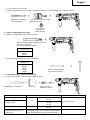
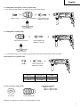
2. Rotation + hammering
This rotary hammer can be set to rotation and
hammering mode by pressing the push button and
turning the change lever to the
mark. (Fig. 6)
(1) Mount the drill bit.
(2) Pull the trigger switch after applying the drill bit tip to
the drilling position. (Fig. 7)
(3) Pushing the rotary hammer forcibly is not necessary
at all. Pushing slightly so that drill dust comes out
gradually is sufficient.
CAUTION:
When the drill bit touches construction iron bar, the
bit will stop immediately and the rotary hammer will
react to revolve. Therefore grip the side handle and
handle tightly as shown in Fig. 7.
3. Rotation only
This rotary hammer can be set to rotation only mode
by pressing the push button and turning the change
lever to the
mark. (Fig. 8)

English
10
To drill wood or metal material using the drill chuck
and chuck adapter (optional accessories), proceed as
follows.
Installing drill chuck and chuck adapter: (Fig. 9)
(1) Attach the drill chuck to the chuck adapter.
(2) The part of the SDS-plus shank is the same as the
drill bit. Therefore, refer to the item of “Mounting the
drill bit” for attaching it.
CAUTION:
䡬 Application of force more than necessary will not
only expedite the work, but will deteriorate the tip
edge of the drill bit and reduce the service life of the
rotary hammer in addition.
䡬 Drill bits may snap off while withdrawing the rotary
hammer from the drilled hole. For withdrawing, it is
important to use a pushing motion.
䡬 Do not attempt to drill anchor holes or holes in
concrete with the machine set in the rotation only
function.
䡬 Do not attempt to use the rotary hammer in the
rotation and striking function with the drill chuck and
chuck adapter attached. This would seriously shorten
the service life of every component of the machine.
4. When driving machine screws (Fig. 10)
First, insert the bit into the socket in the end of chuck
adapter (D).
Next, mount chuck adapter (D) on the main unit
using procedures described in 4 (1), (2), (3), put the
tip of the bit in the slots in the head of the screw,
grasp the main unit and tighten the screw.
CAUTION:
䡬 Exercise care not to excessively prolong driving time,
otherwise, the screws may be damaged by excessive
force.
䡬 Apply the rotary hammer perpendicularly to the screw
head when driving the screw; otherwise, the screw
head or bit will be damaged, or driving force will not
be fully transferred to the screw.
䡬 Do not attempt to use the rotary hammer in the
rotation and hammering function with the drill chuck
and chuck adapter attached.
5. When driving wood screws (Fig. 10)
(1) Selecting a suitable driver bit
Employ cross-recessed screws, if possible, since the
driver bit easily slips off the heads of slotted-head
screws.
(2) Driving in wood screws
䡬 Prior to driving in wood screws, make pilot holes
suitable for them in the wooden board. Apply the bit
to the screw head grooves and gently drive the screws
into the holes.
䡬 After rotating the rotary hammer at low speed for a
while until the wood screw is partly driven into the
wood, squeeze the trigger more strongly to obtain
the optimum driving force.
CAUTION:
Exercise care in preparing a pilot hole suitable for the
wood screw taking the hardness of the wood into
consideration. Should the hole be excessively small
or shallow, requiring much power to drive the screw
into it, the thread of the wood screw may sometimes
be damaged.
6. Hammering only
This rotary hammer can be set to hammering only
mode by pressing the push button and turning the
change lever to the
mark. (Fig. 11)
(1) Mount the bull point or cold chisel.
(2) Press the push button and set the change lever to
middle of
mark and mark. (Fig. 12)
The rotation is released, turn the grip and adjust the
cold chisel to desired position. (Fig. 13)
(3) Turn the change lever to
mark. (Fig. 11)
Then bull point or cold chisel is locked.
7. Using depth gauge (Fig. 14)
(1) Loosen the knob on the side handle, and insert the
depth gauge into the mounting hole on the side
handle.
(2) Adjust the depth gauge position according to the
depth of the hole and thighten the knob securely.
8. How to use the drill bit (taper shank) and the taper
shank adapter
(1) Mount the taper shank adapter to the rotary hammer.
(Fig. 15)
(2) Mount the drill bit (taper shank) to the taper shank
adapter. (Fig. 15)
(3) Turn the switch ON, and drill a hole in prescribed
depth.
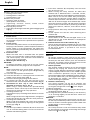
(4) To remove the drill bit (taper shank), insert the cotter
into the slot of the taper shank adapter and strike the
head of the cotter with a hammer supporting on a
rests. (Fig. 16)
HOW TO USE THE CORE BIT
(FOR LIGHT LOAD)
When boring penerating large holes use the core bit (for
light loads). At that time use with the center pin and the
core bit shank provided as optional accessories.
1. Mounting
CAUTION:
Be sure to turn power OFF and disconnect the plug
from the receptacle.
(1) Mount the core bit to the core bit shank. (Fig. 17)
Lubricate the thread of the core bit shank to facilitate
disassembly.
(2) Mount the core bit to the rotary hammer (Fig. 18)
(3) Insert the center pin into the guide plate until it stops.
(4) Engage the guide plate with the core bit, and turn the
guide plate to the left or the right so that it does not
fall even if it faces downward. (Fig. 19)
2. How to bore (Fig. 20)
(1) Connect the plug to the power source.
(2) A spring is installed in the center pin.
Push it lightly to the wall or the floor straight.
Connect the core bit tip flush to the surface and start
operating.
(3) When boring about 5 mm in depth the position of the
hole will be established. Bore after that removing the
center pin and the guide plate from core bit.
(4) Application of excessive force will not only expedite
the work, but will deteriorate the tip edge of the drill
bit, resulting in reduced service life of the rotary
hammer.
CAUTION:
When removing the center pin and the guide plate,
turn OFF the switch and disconnect the plug from the
receptacle.
3. Dismounting (Fig. 21)
Remove the core bit shank from the rotary hammer
and strike the head of the core bit shank strongly two
or three times with a hammer holding the core bit,
then the thread becomes loose and the core bit can
be removed.

English
11
LUBRICATION
Low viscosity grease is applied to this rotary hammer so
that it can be used for a long period without replacing
the grease. Please contact the nearest service center for
grease replacement when any grease is leaking form
loosened screw.
Further use of the rotary hammer with lock off grease
will cause the machine to seize up reduce the service life.
CAUTION:
A special grease is used with this machine, therefore,
the normal performance of the machine may be badly
affected by use of other grease. Please be sure to let
one of our service agents undertake replacement of
the grease.
MAINTENANCE AND INSPECTION
1. Inspecting the drill bits
Since use of a dull tool will cause motor
malfunctioning and degraded efficiency, replace the
drill bit with new ones or resharpen them without
delay when abrasion is noted.
2. Inspecting the mounting screws
Regularly inspect all mounting screws and ensure
that they are properly tightened. Should any of the
screws be loose, retighten them immediately. Failure
to do so could result in serious hazard.
3. Maintenance of the motor
The motor unit winding is the very ”heart” of the
power tool. Exercise due care to ensure the winding
does not become damaged and/or wet with oil or
water.
4. Inspecting the carbon brushes
For your continued safety and electrical shock
protection, carbon brush inspection and replacement
on this tool should ONLY be performed by a Hitachi
Authorized Service Center.
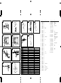
5. Service parts list
A: Item No.
B: Code No.
C: No. Used
D: Remarks
CAUTION:
Repair, modification and inspection of Hitachi Power
Tools must be carried out by a Hitachi Authorized
Service Center.
This Parts List will be helpful if presented with the
tool to the Hitachi Authorized Service Center when
requesting repair or other maintenance.
In the operation and maintenance of power tools, the
safety regulations and standards prescribed in each
country must be observed.
MODIFICATION:
Hitachi Power Tools are constantly being improved
and modified to incorporate the latest technological
advancements.
Accordingly, some parts (i.e. code numbers and/or
design) may be changed without prior notice.
NOTE:
Due to HITACHI’s continuing program of research and
development, the specifications herein are subject to
change without prior notice.

Español
12
PRECAUCIONES GENERALES PARA
OPERACIÓN
¡ADVERTENCIA! Cuando utilice herramientas eléctricas,
tome las medidas de seguridad básicas para reducir el
riesgo de incendios, descargas eléctricas, y lesiones,
incluyendo lo siguiente.
Lea todas todas estas instrucciones antes de utilizar este
producto y guárdelas.
Para realiza roperaciones seguras:
1. Mantener el área de trabajo limpia, áreas y bancos
de trabajo desordenados son causa de daños
personales.
2. Considerar el medio ambiente del área de trabajo.
No exponer las herramientas eléctricas a la lluvia.
No usar herramientas eléctricas en lugares mojados
o húmedos. Mantener el área de trabajo bien
iluminada.
No utilice herramientas eléctricas cuando exista el
riesgo de incendios o de explosión.
3. Protegerse contra descargas eléctricas. Evitar el
contacto del cuerpo con las superficies puestas a
tierra (p. ej., tubos, radiadores, hornos de
microondas, o refrigeradores).
4. Mantener a los niños y a las personas débiles
alejados. No dejar que los visitantes toquen las
herramientas ni los cables de extensión. Todos los
visitantes deberán mantenerse alejados del área de
trabajo.
5. Guardar las herramientas que no se usen y ponerlos
en lugares secos, altos o cerrados, fuera del alcance
de los niños y a las personas débiles.
6. No forzar las herramientas, éstas trabajarán más y
con mayor seguridad cuando cumplan con las
especificaciones para las cuales fueron diseñadas.
7. Usar las herramientas apropiadas. No forzar
pequeñas herramientas o accesorios a realizar el
trabajo de herramientas de mayor potencia. No
utilizar herramientas para otros propósitos para los
cuales no fueron diseñadas, por ejemplo, no utilizar
sierras circulares para cortar ramas de árboles o
troncos.
8. Vestir apropiadamente. No ponerse ropas que
queden flojas ni tampoco joyas. Estas podrian
quedar atrapadas en las partes móviles de las
herramientas. Cuando se trabaje en exteriores, se
recomienda el uso de guantes de goma y calzado
que no resbale. Utilice elementos de protección
para sujetar el cabello largo.
9. Usar gafas de protección. Usar también mascarillas
contra el polvo si las condiciones de corte fuesen
polvorientas.
10. Conecte un equipo colector de polvo.
Si existen dispositivos para la conexión de equipos
de extracción y recolección de polvo, cerciórese de
queéstos estén conectados adecuadamente, y de
utilizarlos en la forma correcta.
11. Cuidar del cable. Nunca lleve las herramientas
colgando del cable, tampoco tire del cable para
efectuar la desconexión de las herramientas.
Mantener el cable alejado del calor, aceite y bordes
agudos.
12. Asegurar la pieza de trabajo usando para ello
abrazaderas o un tornillo. Esto es más seguro que
usar las manos, ademas, ambas manos quedan
libres para operar la herramienta.
13. No extenderse excesivamente para efectuar un
trabajo. Mantener en todo momento un buen
balance y base de apoyo.
14. Mantener cuidadosamente las herramientas.Tener
las siempre limpias y afiladas para obtener un mejor
rendimiento y un funcionamiento más seguro.
Seguir siempre las instrucciones para la lubricación
y el cambio de accesorios. Inspeccionar
periódicamente los cables de las herramientas y si
estuviesen danãdos, hacer que los reparen técnicos
ó expertos. Inspeccionar periodicamente los cables
de extensión y cambiarlos si estuviesen dañados.
Mantener los mangos secos, limpios, y libres de
aceite y grasa.
15. Desconectar las herramientas cuando no se usen,
antes de repararlas, y cuando se cambien accesorios
como por ejemplo, cuchillas, brocas, cortadores, etc.
16. Quitar las cuñas y las llaves de tuercas.
Acostumbrarse a comprobar si se han quitado las
cuñas y las llaves de tuercas antes de poner las
harramientas en funcionamiento.
17. Evitar puestas en funcionamiento sin fin alguno.
No llevar las herramientas con los dedos en los
inerruptores mientras que éstas cestán conectadas.
Cuando se conecten las herramientas, cerciorarse
de que los interruptores esten en la posición de
desconectados.
18. Para usos en exteriores usar cables de extensión.
Cuando las herramientas vayan a ser usadas en
exteriores, usar solamente cables de extensión
diseñados para tal propósito.
19. Estar siempre alerta y poner atención a lo que se
está haciendo, usar el sentido común y no operar
con la herramienta cuando se esté cansado.
20. Comprobar las piezas dañadas. Antes de seguir
con el funcionamiento de las herramientas, las
piezas que estén dañadas deberán comprobarse
cuidadosamente para determinar si pueden
funcionar apropiadamente y cumplir con la función
para las que fueron diseñadas. Comprobar el
alineamiento y agarrotamiento de piezas móviles,
rotura de piezas, montura, y cualiquier otra anomalia
que pudiese afectar al rendimiento de la
herramienta. Cualquier pieza que estuviese dañada
deberá repararse apropiadamente o cambiarse en
un centro de reparaciones autorizado, al menos
que se indique, lo contrario en este manual de
instrucciones. Procurar que los interruptores
defectuosos los cambie un centro de reparaciones
autorizado. No usar las herramientas si sus
interruptores no funcionasen apropiadamente.
21. Advertencia
La utilización de cualquier accesorio o aditivo no
recomendado en este manual de instrucciones
puede conducir al riesgo de lesiones.
22. En caso de avería, haga que su herramienta sea
reparada por un técnico cualificado.
Esta herramienta eléctrica está de acuerfdo con los
requisitos de seguridad pertinentes. Las
reparaciones solamente deberán realizarlas técnicos
cualificadosutilizando piezas de repuesto originales.
De lo contrario, el usuario podría lesionarse.

Español
13
PRECAUCIONES AL USAR EL MARTILLO
PERFORADOR
1. Usar protectores de oídos durante el trabajo.
2. No tocar la broca durante ni inmediatamente después
de trabajar, puesto que se pone ardiente y puede
causar quemaduras serias.
ESPECIFICACIONES
Voltaje (por áreas)* (110V, 115V, 120V, 127V, 220V, 230V, 240V)
Acometida 720W*
Velocidad sin carga 0 – 1150/min.
Velocidad de percusión a carga plena 0 – 4600/min.
Capacidad: hormigón 3,4 – 24 mm
acero 13 mm
madera 32 mm
Peso (sin cable ni mango lateral) 2,5 kg
* Verificar indefectiblemente los datos de la placa de características de la máquina, pues varían de acuerdo con el
país de destino.
3. Antes de empezar a romper, picar o perforar en una
pared, suelo o techo, comprobar cuidadosamente
que no hayan objetos empotrados, tales como cables
o conductos eléctricos.
4. Sujetar siempre firmemente el asidero del cuerpo y
el asidero lateral de la herramienta. De lo contrario,
la contrafuerza producida podría causar un
funcionamiento impreciso e incluso peligroso.
ACCESORIOS ESTANDAR
(1) Caja de plástico .......................................................... 1
(2) Mango lateral .............................................................. 1
(3) Calibre de profundidad .............................................. 1
Los accesorios estándar están sujetos a cambio sin previo
aviso.
ACCESORIOS FACULTATIVOS (de venta por separado)
1. Taladrar orificios de anclaje (rotación + golpeteo)
䡬 Broca de taladro (Eje fino)
Adaptador para eje fino
(SDS plus vástago)
Broca de taladro (Eje fino)
Diámetro externo Longitud efectiva Longitud total
3,4 mm
45 mm 90 mm
3,5 mm
Broca de taladro (Eje fino)

Español
14
Broca de vástago recto
para martillo roto-percutor
( )
Modo cónico Broca de taladro aplicable
Cono Morse (No.1)
Broca de taradro
11,0 ~ 17,5 mm
(vástago cónico)
Cono Morse (No.2)
Broca de taradro
21,5 mm
(vástago cónico)
Cono A El cono A o B troquelado del adaptador cónico as
suministra como accesorio facultativo pero la
Cono B broca para el mismo no se suministra.
䡬 Portabrocas del martillo perforador de 13 mm
Para la operación de taladrado cuando emplee una broca de vástago recto para taladrar con un martillo
perforador.
Diámetro externo
11,0 mm
12,3 mm
12,7 mm
14,3 mm
14,5 mm
17,5 mm
21,5 mm
Llave de portabrocas
Portabrocas del martillo
perforador de 13 mm
(SDS plus vástago)
Adaptador cónico
(SDS plus vástago)
Chaveta
䡬 Broca de taladro (vástago cónico) y adaptador cónico
Broca de taladro (Vástago cónico)
2. Montaje de ancla (golpeteo solamente)
䡬 Adaptador de montaje de ancla (para martillo perforador)
Medida de ancla
W1/4”
W5/16”
W3/8”
Adaptador de montaje de ancla (SDS plus vástago)
(para martillo perforador)
Longitud total: 160, 260 mm

Español
15
Pasador central Barrent tubular (diámetro externo) Espiga de la barrena tubular
–
25 mm
29 mm
(A)
32 mm
Espiga de la barrena tubular (A)
Pasador central (A) 35 mm
38 mm
45 mm
Pasador central (B) (B)
50 mm
Espiga de la barrena tubular (B)
No usar barrenas tubulares Con placa guía
con un diámetro externo de (La placa guía no se ha equipado con barrenas
25 mm y 29 mm. tubulares con diámetro externo de 25 mm y 29 mm.)
4. Trabajo de roturación (golpeteo solamente)
Puntero (tipo redondo) (SDS plus vástago)
Puntero (tipo cuadrado) (SDS plus vástago)
5. Formación de ranuras y ajuste preciso del ancho (golpeteo solamente)
Cortafríos (SDS plus vástago)
Cortador (SDS plus vástago)
䡬 Adaptador de montaje de ancla (para martillo manual)
Medida de ancla
W1/4”
W5/16”
W3/8”
W1/2”
W5/8”
Adaptador de montaje de ancla
(para martillo manual)
3. Pertoración de orificio de diámetro grande (rotación + golpeteo)
䡬 Pasador central, barrena tubular, espiga de la barrena tubular y placa guía.
Pasador central
Barrena
tubular
Espiga de la barrena
tubular
(SDS plus vástago)
(Placa guia)

Español
16
8. Perforación (rotación solamente)
䡬 Portabrocas, adaptador (G) del portabrocas, tornillo especál y llave de portabrocas
Tornillo especial
Llave de portabrocas
Porabrocas
(13 VLRB-D)
Adaptador (G) de portabrocas
(SDS plus vástago)
9. Perforación (rotación solamente)
Portabrocas (13 VLD-D)
Adaptador (D) del portabrocas
(SDS plus vástago)
Liave de portabrocas
7. Trabajo de colocación de pernos para anclaje químico (rotación + golpeteo)
(SDS plus vástago)
Adaptador de anclaje químico de 12,7 mm
Adaptador de anclaje químico de 19 mm
(Manguito
adaptador
a la venta
el mercado)
6. Ranurado (golpeteo solamente)
Cortafríos ranurador (SDS plus vástago)
䡬 Conjunto de portabrocas 13 mm (con llave de portabrocas) y portabrocas (para perforación de orificios en
hormigón o madera)

Español
17
APPLICACION
Rotación y función de golpeteo
䡬 Perforación de orificios de anclaje
䡬 Perforación de orificios de hormigón
䡬 Perforación de orificios de baldosa
Rotación solamente
䡬 Perforación de orificios en hormigón o madera
(con accesorios facultativos)
䡬 Apretar tornillos en metal o madera
(con accesorios facultativos)
Función de golpeteo solamente
䡬 Cincelado ligero de hormigón, formación de ranuras
y ajuste preciso del ancho.
ANTES DE LA PUESTA EN MARCHA
1. Alimentación
Asegurarse de que la alimentación de red que ha de
ser utilizada responda a las exigencias de corriente
especificadas en la placa de características del
producto.
2. Conmutador de alimentación
Asegurarse de que el conmutador de alimentación
esté en la posición OFF (desconectado). Si la clavija
está conectada en la caja del enchufe mientras el
conmutador de alimentación esté en posición ON
(conectado) las herramientas eléctricas empezarán a
trabajar inmediatamente, provocando un serio
accidente.
3. Cable de prolongación
Cuando está alejada el área de trabajo de la red de
alimentación, usar un cable de prolongación de un
grosor y potencia nominal suficiente. El cable de
prolongación debe ser mantenido lo más corto
posible.
4. Montaje de la broca (Fig. 1)
PRECAUCION:
Para evitar accidentes, cerciórese de desactivar y de
desconectar el enchufe del tomacorriente.
NOTA:
Cuando ulilice herramientas como por ejemplo:
cinceles, brocas de taladro, etc., cerciórese de utilizar
piezas genuinas diseñadas por nuestra compañía.
(1) Limpie la parte del vástago de la broca de taladro.
(2) Inserte la broca de taladro girando en el sujetador de
la herramienta hasta que se asegure bien. (Fig. 1)
(3) Verifique si esta bien asegurado tirando de la broca
de taladro.
(4) Para extraer la broca, tire completamente de la
empuñadura en el sentido de la flecha y tire hacia
afuera de la broca. (Fig. 2)
5. Cuando instale la copa de polvo o el lector de polvo
(B) (Accesorios facultativos)(Fig. 3, Fig. 4)
Cuando emplee un martillo perforador para trabajos
de taladrado hacia arriba, extraiga el adaptador de
recolección de polvo e instale una copa de polvo o un
colector de polvo (B) para recolectar las partículas a
fin de facilitar la operación.
䡬 Instalación de la copa de polvo
Emplee la copa de polvo instalando la broca como se
muestra en la Fig. 3.
Cuando emplee una broca de gran diámetro, agrande
el orificio central de la copa de polvo con este martillo
perforador.
䡬 Instalación del colector de polvo (B)
Para emplear el colector de polvo (B), Insértelo desde
la punta de la broca alineándolo con la ranura de la
empuñadura. (Fig. 4)
No. de broca
Adaptador (D) del portabrocas
(SDS plus vástago)
No. de broca
Tamaño del tornillo
Longitud
No.2 3 – 5 mm 25 mm
No.3 6 – 8 mm 25 mm
11. Copa de polvo, Colector de polvo (B)
Los accesorios de norma están sujetos a cambio sin previo aviso.
12. Grasa A para martillo
500 g (en una lata)
70 g (en un tubo naranja)
30 g (en un tubo naranja)
Colector de polvo (B)
Copa de polvo
10. Colocación de tornillos (rotación solamente)

Español
18
PRECAUCIÓN:
䡬 La copa de polvo y el colector de polvo (B) son para
emplearse exclusvamente en trabajos de perforación
de hormigón. No los emplee para trabajar con madera
o metal.
䡬 Inserte completamente el colector de polvo (B) en la
parte del portabrocas de la unidad principal.
䡬 Cuando ponga en funcionamiento del martillo
perforador meintras el colector de polvo (B) esté
separado de la superficie de hormigón, dicho colector
girará junto con la broca. Cerciórese de apretar el
gatillo interruptor después de haber presionado la
copa de polvo sobre la superficie de hormigón.
(Cuando emplee la copa de polvo con una broca de
no más de 190 mm de longitud total, el colector de
polvo (B) no podrá tocar la superficie de hormigón
girará. Por lo tanto, emplee el colector de polvo (B)
con brocas de 166, 160, y 110 mm de longitud total.)
䡬 Vacíe las partículas del colector de polvo (B) después
de haber taladrado dos o tres orificios.
䡬 Después de haber extraído el colector de polvo (B),
vuelva a colocar a broca.
6. Selección de la broca destornillador
Puede dañarse las cabezas de tornillos y las brocas
de atornillar menos que se emplee la broca apropiada
según sea el diámetro del tornillo.
7. Confirmar la dirección de rotación de la broca (Fig. 5)
La broca rota hacia la derecha (mirándola desde atrás)
al oprimir el lado R (der.) de la tecla. El lado L (izq.) de
la tecla se usa para hacer girar la broca a la izquierda.
COMO SE USA
PRECAUCIÓN:
Para evitar accidentes, cerciórese de poner este
interruptor en OFF y de desconectar el enchufe del
tomacorriente cuando instale o extraiga brocas y
otras piezas. El interruptor de alimentación también
deberá ponerse en OFF durante un descanso en el
trabajo y después de haber finalizado dicho trabajo.
1. Operación del conmutador
La velocidad rotatoria de la broca de taladro puede
ser controlad variando la fuerza con la que se aprieta
el pulsador. La velocidad está baja cuando se aprieta
ligeramente el pulsador y se aumenta al apretar más
el pulsador. La operación contínua puede ser
alcanzada apretando el pulsador y apretando hacia
abajo el dispositivo de ajuste. Para ponel el pulsador
en OFF (desconectado) volver a apretar el pulsador
para desconectar el dispositivo de ajuste, y soltar el
pulsador a su posición normal.
2. Rotación + golpeteo
Este martillo perforador se puede ajustar en el modo
de rotación y en el modo de golpeteo pulsando la
tecla y girando la palanquita selectora a la marca
. (Fig. 6)
(1) Montar la broca.
(2) Presionar el interruptor de gatillo después de poner
la punta de la broca en la posición para taladrar. (Fig. 7)
(3) No es necesario presionar con fuerza la broca.
Presionar ligeramente la broca de forma que el polvo
producido al taladrar salga al exterior gradualmente.
PRECAUCIÓN:
Cuando la broca toque una barra de hierro de
construción se detendrá inmediatamente y el martillo
perforador tenderá a girar. Por lo tanto, sujetar el
mango lateral y sostenerlo firmemente como se ilustra
en la Fig. 7.
3. Rotación solamente
Este martillo selector sólo se puede ajustar en el
modo de rotación pulsando la tecla y girando la
palanquita selectora a la marca
. (Fig. 8)
Para perforar madera o metal empleando el
portabrocas y el adaptador del portabrocas (accesorio
facultativo), proceder como sigue.
Instalación del portabrocas y adaptador del
portabrocas: (Fig. 9)
(1) Instale la broca en el adaptador del portabrocas.
(2) La parte del SDS plus vástago es igual que una
broca. Por lo tanto, para instalarla, consulte ”Montaje
de la broca”.
PRECAUCIÓN:
䡬 La aplicación de fuerza excesiva acelerará el trabajo
pero dañará la punta de la broca y reducirá la vida
útil del martillo perforador.
䡬 La broca puede salirse al quitar el martillo perforador
del orificio perforado. Para extraer esta herramienta
es importante empujar hacia de lante.
䡬 No intentar perforar orificios de anclaje o perforar el
concreto con la máquina puesta en la función de
rotación solamente.
䡬 No intentar usar el martillo perforador en la función
de rotación y golpeteo con el portabrocas y el
adaptador del portabrocas instalados. Esto reducirá
considerablemente la vida útil de cada componente
de la máquina.
4. Cuando coloque tornillos para metal (Fig. 10)
En primer lugar, inserte la broca en el cubo del
extremo del adaptador (D) de portabroca.
A continuación, monte el adaptador (D) de portabroca
en la unidad principal empleando los procedimientos
descritos en 4 (1), (2), y (3), coloque la punta de la
broca en las ranuras de la cabeza del tornillo, sujete
la unidad principal, y apriete el tornillo.
PRECAUCIÓN:
䡬 Tener cuidado en no prolongar excesivamente el
accionamiento de la herramienta, ya que de lo
contrario, pueden dañarse los tornillos por el exceso
de fuerza.
䡬 Colocar el martillo perforador en forma perpendicular
sobre la cabeza del tornillo al atornillarlo, ya que en
caso contrario, puede dañarse la cabeza del tornillo o
la broca, e incluso, la fuerza de accionamiento puede
que no se transfiera por completo al tornillo.
䡬 No intentar usar el martillo perforador en la función
de rotación y golpeteo con el portabrocas y el
adaptador del portabrocas instalados.
5. Atornillando tornillos para madera (Fig. 10)
(1) Emplear tornillos de cabeza estrellada en lo posible,
debido a que los tornillos de cabeza ranurada hacen
que se zafe fácilmente el destornillador.
(2) Atornillado
䡬 Antes de atornillar los tornillos para madera, hay que
hacer orificios apropiados en la madera, aplicando
luego la broca destornillador en la cabeza del tornillo
y colocar asi éste en los orificios.

Español
19
䡬 Luego de hacer rotar la herramienta lentamente hasta
que el tornillo quede parcialmente metido en la
madera, apretar más el gatillo para obtener la fuerza
óptima de atornillado.
PRECAUCIÓN:
Tener cuidado al preparar el orificio para que sea
apropiado para el tornillo, teniendo en cuenta la
dureza de la madera. Si el orificio es excesivamente
pequeño o estrecho, se requiere mucha fuerza para
atornillar y a veces puede dañarse la rosca.
6. Golpeteo solamente
Este martillo perforador se puede ajustar en el modo
de golpeteo solamente pulsando la tecla y girando la
palanquita selectora a la marca
. (Fig. 11)
(1) Instale el puntero o el cortafríos.
(2) Pulse la tecla y ajuste la palanquita selectora en
medio de la marca
y la marca . (Fig. 12)
El giro se libera, gire sujetador y ajuste el cortafríos
en la posición deseada. (Fig. 13)
(3) Gire la palanquita selectora a la marca
. (Fig. 11)
Entonces se bloqueará el puntero o el cortafríos.
7. Modo de usar el tope (Fig. 14)
(1) Afloje el perno de perilla del asa lateral, e inserte el
retenedor en el surco en U de dicha asa lateral.
(2) Ajustar la posición del retenedor de acuerdo a la
profundidad del agujero, y apretar firmemente el
perno de perilla.
8. Modo de usar la broca (espiga ahusada) y el adaptador
de la espiga ahusada
(1) Montar el adaptador de la espiga ahusada en el martillo
perforador (Fig. 15).
(2) Montar la broca (espiga ahusada) en el adaptador de
la espiga ahusada (Fig. 15)
(3) Poner el interruptor en la posición de encendido
(ON), y taladrar un agujero de la profundidad
especificada.
(4) Para quitar la broca (espiga ahusada), insertar la
chaveta en la ranura del adaptador de la espiga
ahusada y golpear la cabeza de la chaveta con un
martillo. Usar apoyos como se muestra en la Fig. 16.
MODO DE USAR LA BARRENA TUBULAR
(PARA CARGAS LIGERAS)
Cuando se tengan que taladrar agujeros grandes, usar la
barrena tubular (para cargas ligeras). Usar también el
pasador central y la espiga de la barrena tubular provistos
como accesorios opcionales.
1. Montaje
PRECAUCIÓN:
Cerciorarse de poner el interruptor de la alimentación
en la posición de apagado (OFF) y de desconectar el
enchufe de la toma de alimentación.
(1) Montar la barrena tubular en su espiga. (Fig. 17)
Lubricar la rosca de la espiga de la barrena tubular
para facilitar el desmontaje.
(2) Montar la espiga de la barrena tubular en el martillo
perforador. (Fig. 18)
(3) Insertar el pasador central en la placa guía hasta que
se pare.
(4) Unir la placa guía con la barrena tubular y girar la
placa guía hacia la izquierda o hacia la derecha de
forma que no se caiga a pesar de estar indicando
hacia abajo. (Fig. 19)
2. Modo de taladrar (Fig. 20)
(1) Conectar el enchufe a la toma de alimentación.
(2) El pasador central se ha instalado un resorte.
Presionar ligeramente y sin torcerse hacia la pared o
hacia el pared o hacia el suelo.
Procurar que toda la punta de la barrena tubular esté
en contacto con la superficie a taladrar y luego,
empezar la operación.
(3) Al taladrar aproximadamente 5 mm en profundidad,
la posición del agujero queda ya establecida. Quitar
el pasador central y la placa guía de la barrena tubular
y seguir taladrando.
(4) La aplicación de una fuerza excesiva acelerará el
cumplimiento del trabajo, pero deteriorará la punta
de la broca reduciendo la duración del martillo
perforador.
PRECAUCIÓN:
Cuando se quite el pasador central y la placa guía,
poner el interruptor en la posición de apagado (OFF)
y desconectar el enchufe de la toma de alimentación.
3. Desmontaje (Fig. 21)
Como otro método, quitar la espiga de la barrena
tubular del martillo perforador y golpear fuertemente
la cabeza de la espiga de la barrena tubular dos o tres
veces con un martillo sujetanto la punta de la barrena.
La parte roscada se aflojará y la barrena tubular
podrá quitarse.
LUBRICACION
A este martillo perforador deberá aplicársele grasa de
baja viscosidad,de esta forma, el martillo podrá usarse
durante un largo período de tiempo sin cambiar de
grasa. Ponerse por favor en contacto con el agente de
reparaciones más cercano para cambiar la grasa si ésta
se escapase a través de los tornillos flojos.
La falta de grasa hará que el martillo perforador se
agarrote disminuyendo por lo tanto su duración.
PRECAUCIÓN:
En esta herramienta deberá usarse la grasa
especificada. El uso de otras grasas podría afectar
negativamente al rendimiento. Cerciórese de
preguntar a sus agentes de servicio por la grasa de
repuesto.
MANTENIMENTO E INSPECCION
1. Inspeccionar la broca de taladro
Debido a que el uso de brocs desafiladas pueden
causar mal funcionamiento del motor y desmejorar
la eficacia del taladro, hay que reemplazar las brocas
en malas condiciones por nuevas o afilarlas de
inmediato al advertir abrasión.
2. Inspeccionar los tornillos de montaje
Regularmente inspeccionar todos los tornillos de
montaje y asegurarse de que estén apretados
firmemente. Si cualquier tornillo estuviera suelto,
volver a apretarlo inmediatamente. El no hacer esto
provocaría un riesgo serio.
3. Mantenimiento de motor
La unidad de bobinado del motor es el verdadero
corazón” de las herramientas eléctricas. Prestar el
mayor cuidado y asegurarse de que el bobinado no
se dañe y/o se humedezca con aceite o agua.

Español
20
4. Inspección de las escobillas
Por motivos de seguridad contra descargas
eléctricas, la inspección y el reemplazo de las
escobillas deberán realizarse SOLAMENTE en un
Centro de Servicio Autorizado de Hitachi.
5. Lista de repuestos
A: N°. ítem
B: N°. código
C: N°. usado
D: Observaciones
PRECAUCIÓN:
La reparación, modificación e inspección de las
herramientas eléctricas Hitachi deben ser realizadas
por un Centro de Servicio Autorizado de Hitachi.
Esta lista de repuestos será de utilidad si es
presentada junto con la herramienta al Centro de
Servicio Autorizado de Hitachi, para solicitar la
reparación o cualquier otro tipo de mantenimiento.
En el manejo y el mantenimiento de las herramientas
eléctricas, se deberán observar las normas y
reglamentos vigentes en cada país.
MODIFICACIONES:
Hitachi Power Tools introduce constantemente
mejoras y modificaciones para incorporar los últimos
avances tecnológicos.
Por consiguiente, algunas partes (por ejemplo,
números de códigos y/o diseño) pueden ser
modificadas sin previo aviso.
NOTA:
Debido al programa continuo de investigación y
desarrollo de HITACHI estas especificaciones están
sujetas a cambio sin previo aviso.
Page is loading ...
Page is loading ...
Page is loading ...
Page is loading ...
Page is loading ...
Page is loading ...
Page is loading ...
Page is loading ...
Page is loading ...
Page is loading ...
Page is loading ...
Page is loading ...
Page is loading ...
-
 1
1
-
 2
2
-
 3
3
-
 4
4
-
 5
5
-
 6
6
-
 7
7
-
 8
8
-
 9
9
-
 10
10
-
 11
11
-
 12
12
-
 13
13
-
 14
14
-
 15
15
-
 16
16
-
 17
17
-
 18
18
-
 19
19
-
 20
20
-
 21
21
-
 22
22
-
 23
23
-
 24
24
-
 25
25
-
 26
26
-
 27
27
-
 28
28
-
 29
29
-
 30
30
-
 31
31
-
 32
32
-
 33
33


Hikoki DH 24PC2 User manual
- Category
- Rotary hammers
- Type
- User manual
- This manual is also suitable for
Ask a question and I''ll find the answer in the document
Finding information in a document is now easier with AI
in other languages
- español: Hikoki DH 24PC2 Manual de usuario
Related papers
Other documents
-
Hitachi DH24PB2 Handling Instructions Manual
-
-
Hitachi DH 24PM User manual
-
-
-
-
-
-
-