Page is loading ...

P/N R9340-0104 1 © 2010 RAILWAY EQUIPMENT CO.
REV B
5/11
OPERATING MANUAL
MODEL NO. 934
ELECTRIC HOT AIR BLOWER
TRACK SWITCH SNOW MELTER
480 / 230 VAC 1 & 3 PHASE
50KW AND 60 KW LOAD CAPACITY
MANUFACTURED
BY
RAILWAY EQUIPMENT COMPANY
15400 MEDINA ROAD
PLYMOUTH, MINNESOTA 55447
TEL. 763-972-2200
FAX. 763-972-2900
E-Mail:
Support: [email protected]
Sales: [email protected]

P/N R9340-0104 2 © 2010 RAILWAY EQUIPMENT CO.
REV B
5/11
CAUTION
GENERAL HAZARD WARNING
FAILURE TO COMPLY WITH THE PRECAUTIONS AND INSTRUCTIONS
PROVIDED WITH THIS HEATER, CAN RESULT IN DEATH, SERIOUS INJURY
AND PROPERTY LOSS OR DAMAGE FROM HAZARDS OF FIRE,
EXPLOSION, BURN, ASPHYXIATION, CARBON MONOXIDE POISONING,
AND/OR ELECTRICAL SHOCK.
ONLY PERSONS WHO CAN UNDERSTAND AND FOLLOW THESE
INSTRUCTIONS SHOULD USE OR SERVICE THIS HEATER.
IF YOU NEED ASSISTANCE OR HEATER INFORMATION, SUCH AS
INSTRUCTION MANUALS, LABELS, ETC., CONTACT THE
MANUFACTURER.
CAUTION
WARNING: FIRE, BURN, INHALATION, AND EXPLOSION HAZARD.
KEEP SOLID COMBUSTIBLES, SUCH AS BUILDING MATERIALS, PAPER OR
CARDBOARD, A SAFE DISTANCE AWAY FROM THE HEATER AS
RECOMMENDED BY THE INSTRUCTIONS. NEVER USE THE HEATER IN
SPACES WHICH DO OR MAY CONTAIN VOLATILE OR AIRBORNE
COMBUSTIBLES, OR PRODUCTS SUCH AS GASOLINE, SOLVENTS, PAINT
THINNER, DUST PARTICLES OR UNKNOWN CHEMICALS.

P/N R9340-0104 3 © 2010 RAILWAY EQUIPMENT CO.
REV B
5/11
PLEASE READ THIS INSTRUCTION MANUAL ENTIRELY BEFORE
HANDLING THIS MATERIAL OR ATTEMPTING TO INSTALL, OPERATE
OR SERVICE THIS HOT AIR BLOWER SYSTEM.
PLEASE READ THE WARNINGS AND CAUTIONS LISTED BELOW.
CAUTION
CAUTION
CAUTION
CAUTION
TWO (2) COMPLETE INSTRUCTION MANUALS HAVE BEEN INCLUDED WITH THIS
SNOW MELTER SYSTEM. PLEASE KEEP ONE OF THE MANUALS WITH THE SYSTEM
AFTER INSTALLATION. ANYONE OPERATING OR SERVICING THIS SNOW MELTER
SYSTEM SHOULD READ THE MANUAL ENTIRELY BEFORE PROCEEDING.
IF YOU HAVE ANY QUESTIONS CONCERNING THE MANUFACTURE, DESIGN,
FUNCTION, INSTALLATION, OPERATION OR MAINTENANCE, CONTACT
RAILWAY EQUIPMENT COMPANY BEFORE PROCEEDING.
SHEET METAL EDGES MAY BE VERY SHARP AND CAN
CAUSE SEVERE CUTS OR LACERATIONS. PROTECTIVE
GLOVES AND CLOTHING SHOULD BE WORN. USE
CAUTION WHEN HANDLING ALL SHEET METAL
COMPONENTS.
THIS HOT AIR BLOWER TRACK SWITCH SNOW MELTER
SYSTEM CAN BE OPERATED REMOTELY OR BY A SNOW
DETECTOR SYSTEM. THEREFORE, OPERATION MAY
BEGIN UNEXPECTEDLY. USE CAUTION WHEN IN THE
AREA.
SYSTEM OPERATES WITH VARIOUS VOLTAGE LEVELS
UP TO 600VAC. CONTACT WITH ELECTRICITY CAN BE
HAZARDOUS OR LETHAL. MAKE SURE THAT THE MAIN
CIRCUIT BREAKER IS TURNED OFF BEFORE
ATTEMPTING TO SERVICE THIS SYSTEM. EVEN WITH
CIRCUIT BREAKER OFF LINE VOLTAGE IS PRESENT AT
THE TOP CIRCUIT BREAKER CONNECTIONS.
THIS SYSTEM CONTAINS A HIGH SPEED AIR FAN
WHICH ROTATES AT UP TO 3600RPM AND CREATES
FORCEFUL SUCTION WHEN OPERATING. DO NOT
OPERATE THE BLOWER SYSTEM IF ANY OF THE
DUCTWORK COMPONENTS HAVE BEEN REMOVED.

P/N R9340-0104 4 © 2010 RAILWAY EQUIPMENT CO.
REV B
5/11
TABLE OF CONTENTS
I. GENERAL INFORMATION 6
A. MODEL NUMBER DESCRIPTION 6
B. STANDARD FEATURES 7
II. COMPONENT DESCRIPTION 8
A. MAIN HAB UNIT 8
B. STANDARD DUCTWORK 8
C. OPTIONAL DUCTWORK 9
III. INSTALLATION 12
A. TIE DUCT 12
B. MAIN HAB UNIT 13
C. POINT NOZZLES AND TRACK DUCTS 14
F. ELECTRICAL CONNECTION 17
IV. CONTROL MODULE 18
A. DESCRIPTION 18
B. MODULE CONTROLS AND INDICATORS 18
C. FAULT CONDITIONS 20
D. ADVANCED FEATURES 23
E. OPERATION 27
V. SEASONAL MAINTENANCE 28
VII. TROUBLESHOOTING 29
A. UNIT DOES NOT START 29
B. LOW HEAT LEVEL 29
C. LOW AIRFLOW 29
VIII. SNOW DETECTOR 30
A. INSTALLATION 30
B. OPERATION 31
C. MAINTENANCE 31
D. TROUBLESHOOTING 32
IX. SPECIFICATIONS 33
X. DRAWINGS 34
XI. LIMITED WARRANTY 35

P/N R9340-0104 5 © 2010 RAILWAY EQUIPMENT CO.
REV B
5/11
I. GENERAL INFORMATION
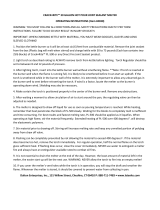
A. MODEL NUMBER DESCRIPTION
OPTIONS
0
= STANDARD
1
= GE IN TIE SWITCH
2
= GE SNF IN TIE SWITCH
3
= TRACK DUCT NOZZLES FOR SNF DUCT
4
= 3/5 PANEL CONFIGURED
10X10 ADAPTOR FLANGE
AND NOZZLE (NO TIE DUCT)
5
= 2HP PANEL CONFIGURED
10X10 ADAPTOR FLANGE
AND NOZZLES (NO TIE DUCT)
6
= 2HP USING 10X10 TIE DUCT
7
= STANDARD WITH FLEX NOZZLES
XXX X X X X
OUTLET DUCT
K
= STEEL TIE DUCT WITH 115# PLATES 9'
N
= STEEL TIE DUCT WITH 136# PLATES 9'
G
= STEEL TIE DUCT WITH 115# PLATES FOR SNF
H
= STEEL TIE DUCT WITH 136# PLATES FOR SNF
T
= NO TIE DUCT
C
- CUSTOM TIE DUCT
2.13.09 TM
MODEL
934
2HP High Profile
937
2HP Low Profile
INCOMING
POWER
1
= 230VAC 1PH
2
= 460VAC 1PH
3
= 230VAC 3PH
4
= 460VAC 3PH
5
= 575VAC 3PH
POWER
50
= 50 KW
60
= 60 KW
X
TRACK DUCT LENGTH
0
= NO TRACK DUCT
1
= 10' TRACK DUCT
2
= 20' TRACK DUCT
3
= 30' TRACK DUCT
4
= 40' TRACK DUCT
5
= 15' TRACK DUCT
X
REVISION
LEVEL
Electric Hot Air Blowers

P/N R9340-0104 6 © 2010 RAILWAY EQUIPMENT CO.
REV B
5/11
B. STANDARD FEATURES OF TRACK SWITCH HOT AIR BLOWER
1. Direct drive motor, totally enclosed fan cooled.
2. High efficiency, quiet operation blower.
3. Voltage sensor to prevent low or high voltage damage.
4. Current coils for open heater detection.
5. Remote operation via contact closure (low voltage, low current) with
timed shut off.
6. Built-in snow detector system (requires Snow Detector assembly option).
7. Auto-Off-Local switch.
8. High temperature limit thermostat/shut off.
9. Adjustable air temperature control.
10. Adjustable rail temperature control.
11. Reply indication via EHAB contact closure.
12. Fail indication via EHAB contact closure.
13. Main circuit breaker.
14. Audible tone before blower startup
15. Weather tight gasketed control enclosure
16. Status indicating lights for all control functions
17. Start delay timer for sequential startup
18. Run timer for timed operation
19. Selectable "Transparent" snow detector operation
20. Snow detect timer
21. All ductwork and nozzles are thermally and electrically isolated from
tracks
22. Quick-release track duct
23. Blower motor starter with overload protection
24. Elevated air intake
25. Adjustable delay for start up (1 Sec. -4.5 Min.)
26. All components mounted and wired within main unit – no external wiring
required except for remote control, indications and optional snow
detectors.
27. Galvanized case constructed of 14-gauge steel, high temperature powder
coated finish.
28. Convenient panel access to fuses and heating elements.
29. Galvanized steel adjustable mounting foundations.
30. Standard ductwork: heat duct with straight insulated flexible
duct and heavy duty insulated offset duct connects to main tie duct
electrically insulated between rails, 24 inch (minimum) switch point
nozzles.

P/N R9340-0104 7 © 2010 RAILWAY EQUIPMENT CO.
REV B
5/11
II. COMPONENT DESCRIPTION
A. MAIN HOT AIR BLOWER (HAB) UNIT
1. MAIN CIRCUIT BREAKER: Provides main over-current protection and
manual on-off control of electrical power.
2. MOTOR CONTACTOR: Provides automatic blower motor control, with high
current contacts.
3. MOTOR OVERLOAD RELAY: Protects the blower motor from an over-
current condition.
4. CONTROL MODULE: Provides complete control of operation. See separate
description and details, section IV.
5. AIRFLOW SWITCH: Located in the heat duct, the sail switch indicates proper
airflow before and during burner operation. The differential setting is determined
by elevation.
6. AIR TEMPERATURE SENSOR: This is an analog type sensing circuit to
monitor the ambient air temperature.
7. BLOWER MOTOR: The motor is totally enclosed and fan cooled.
8. BLOWER: The high efficiency blower wheel is dynamically balanced for
smooth and quiet operation.
9. BUZZER: The buzzer will sound a 10-second tone immediately before the
motor contactor is energized.

P/N R9340-0104 8 © 2010 RAILWAY EQUIPMENT CO.
REV B
5/11
B. STANDARD DUCTWORK
1. HEAT DUCT: The first section of ductwork attached to the main HAB unit.
This duct contains the heaters, fuses, air flow switch and overtemp.
2. FLEX DUCT: Connects the heat duct to the offset duct. It is a section of
flexible duct, enclosed in an insulated sheet metal wrapper.
3. HEAVY DUTY OFFSET DUCT: Connects the flex duct to the tie outlet duct.
This duct provides an 8” offset.
4. TIE OUTLET DUCT: The outlet duct extends under the rails in place of a tie
and directs the airflow to the point nozzles and track ducts. The rail attaches to
the duct using tie plates and E clips. The tie plates are electrically insulated from
the rail using an insulating kit. There are six openings in the top for point nozzles
and track duct nozzles. Refer to the drawing page for the duct layout.
5. TRACK DUCTS: These ducts rest on brackets on the ties and the outlet duct.
They are installed over the track duct nozzles. The track ducts consist of a 5’
point, a 5’ mid, and 10’ sections to complete the desired length.
6. TRACK DUCT NOZZLE: Attaches to the inner two rectangular openings on
the top of the outlet duct. Directs airflow down the length of the switch through
the track ducts.
7. TRACK DUCT NOZZLE ISOLATING KIT: This is an electrically insulating
gasket with insulating washers and hardware to provide isolation between the
nozzles and the outlet duct. Refer to drawing 9278-0027 for proper installation.
8. QUICK CHANGE NOZZLE PLATE: This plate allows for quick removal or
installation of nozzles to the tie duct, by simply loosening of four bolts the nozzle
assembly can be removed or installed.
9. TRACK DUCT SUPPORT BRACKET: These brackets are used to secure the
track duct in position. Refer to drawing 92774.
10. SWITCH POINT NOZZLE: These nozzles direct heated air down the switch
point. They are mounted on the outlet duct. They can be adjusted for proper
airflow direction. Nozzles may be shortened by up to 10” for proper fit.
11. POINT NOZZLE ISOLATING KIT: This is an electrically insulating gasket
with insulating washers and hardware to provide isolation between the nozzles
and the outlet duct. Refer to drawing 9278-0021 for proper installation.

P/N R9340-0104 9 © 2010 RAILWAY EQUIPMENT CO.
REV B
5/11
C. OPTIONAL DUCTWORK
1. EXTENSION DUCTS: Extension ducts of various lengths are available to meet
specific requirements. These are insulated and enclosed in a metal wrapper.
Make sure the duct is mounted in the correct orientation, as there is an access
opening underneath the insulating wrapper cover. If additional duct extensions
are required, this assembly can be added between the outlet duct and the offset
duct.
2. 7’ TRACK DUCT: These track ducts are seven feet long. They are often
mounted outside of the track near the switch machine. A kit is available (P/N
9278-0270) that includes a 7’ track duct, a track duct nozzle and a track duct
isolation kit.
OTHER DUCTWORK ASSEMBLIES ARE AVAILABLE. CONSULT THE
FACTORY FOR SPECIAL DUCTWORK NEEDS.

P/N R9340-0104 10 © 2010 RAILWAY EQUIPMENT CO.
REV B
5/11
(INTENTIONALLY LEFT BLANK)

P/N R9340-0104 11 © 2010 RAILWAY EQUIPMENT CO.
REV B
5/11
III. INSTALLATION
INSTALLATION SHOULD BE DONE IN THIS ORDER:
A. TIE DUCT OUTLET DUCT/OFFSET DUCT
B. MAIN HAB UNIT/FLEX DUCT
C. POINT NOZZLES AND TRACK DUCTS
D. ELECTRICAL
A. TIE DUCT
1. Remove the appropriate tie. Choose the tie that will result in the point nozzles
being as close to the switch point as possible without interfering with normal
switch operation. The distance from the center of the tie duct to the end of the
point nozzles is 33”. If necessary, up to 10” may be cut off each point nozzle.
2. Remove sufficient ballast to provide at least 14” clearance from the bottom of the
rails.
3. Carefully slip the tie duct under the rails and position it so that the rails are
directly above the tie plates. Ensure that the tie duct is centered between the
adjacent ties.
4. Place a rubber pad on the tie plate, then using a suitable lever, raise one end of the
tie duct until the rail lies correctly on the pad on the tie plate. Place two e-clip
insulators, one on each side of rail, in place and then fasten the rail to the tie plate
using two of the four 927248 rail clips. Use a heavy hammer or maul to drive the
clips securely into place.
5. While keeping the tie duct supported in place, firmly pack ballast under the tie
duct from the rail out to the end.
6. Repeat steps 4 and 5 for the other end of the tie duct.
7. a. Remove the end flange plate nearest the HAB by loosening the six
retainer bolts.
b. Install the two-foot heavy duty offset duct (P/N 9278-3403) to the tie duct
using hardware and gasket supplied with the offset duct.
8. Firmly repack ballast under the entire tie duct.
PLEASE READ THROUGH THE ENTIRE
INSTRUCTIONS BEFORE BEGINNING INSTALLATION.

P/N R9340-0104 12 © 2010 RAILWAY EQUIPMENT CO.
REV B
5/11
B. MAIN HAB UNIT
1. The main HAB unit has four slotted mounting holes on 15-1/2” x 34-1/2” centers.
2. Refer to Foundation Assembly drawing for the assembly of the optional
mounting foundation.
3. Use the provided EHAB positioning drawings to determine the approximate
position and height of the mounting foundation. The top of the foundation should
be placed 4"-6" below the height of the ties. This will allow final adjustment of
the HAB unit. NOTE: The drawing shows a standard HAB unit, but can be
used for the low profile series, also.
4. Excavate and place the foundation in its proper location.
5. Refer again to the drawing of the Foundation Assembly, detail A, showing the
mounting bolt arrangement. Attach four 3/4-10 x 8" hex bolts in the slotted holes
of the blower base, using a washer on each side of the blower base and a hex nut.
Draw the hex nut hand-tight and then loosen one turn.
6. Thread a hex nut about halfway onto each bolt.
7. Place the blower unit on the foundation using a flat washer on the top and bottom
of the foundation and another hex nut on the bottom. The slotted holes in the
foundation will allow for side-to-side adjustment, and the slotted holes in the
HAB base will allow front-to-back adjustment. However, do not tighten the
mounting nuts yet.
8. Install the 24” flex duct onto the HAB flame duct.
9. Now adjust the HAB unit side to side, up or down, and forward or backward to
obtain the proper alignment of the heat duct to the offset duct. It may be
necessary to adjust the position of the offset/outlet duct assembly. The
adjustments should be made so that there is no stress on any of the ductwork, also
flex duct should measure 30”. Again, leave the mounting nuts loose for now.
10. Connect the other end of the flex duct to the HD offset duct.
11. With all components in the proper position, the foundation nuts may
now be tightened.
12. The fill can now be replaced around the mounting foundations.

P/N R9340-0104 13 © 2010 RAILWAY EQUIPMENT CO.
REV B
5/11
13. Adjustable air intake screens. To start the GHAB in a new location, set the
intake screens in the closed position. If there proves to be a moisture problem
where frost builds up on the intake screens, the intake screens can be set in the
open position to improve the airflow into the blower.
14. The airflow switch differential setting is factory set on “D” which is for
elevations below 2000 ft. If your location is set at a higher elevation,
This differential setting will need to be adjusted. Adjust per the
following instructions:
a. Remove the galvanized cover over the airflow switch.
b. Remove the cover from the airflow switch.
c. Adjust the differential wheel on the base of the airflow switch as
follows:
Below 2000 ft elevation, set Airflow Differential Wheel to “D”
Below 4000 ft elevation, set Airflow Differential Wheel to “C”
Below 6000 ft elevation, set Airflow Differential Wheel to “B”
Above 6000 ft elevation, set Airflow Differential Wheel to “A”
C. POINT NOZZLES AND TRACK DUCTS
REFER TO THE GHAB POSITIONING DRAWING FOR TRACK DUCT
AND POINT NOZZLE POSITIONS.
LH AND RH POINT/TRACK NOZZLE ASSEMBLIES
1. Attach point/track nozzle assembly RH (P/N 9508-4000) and point/track nozzle
assy LH (P/N 9508-4001) to the openings in the tie duct. Position assemblies for
proper airflow direction.
2. Assemble the individual track duct sections into two complete track duct sections.
The mid and heel sections contain splices wrapped around the outside of the duct.
Unhook the clips to remove the three cover pieces. The bottom can now be
removed from the duct.
To assemble the splice:
a. Center the bottom splice piece on the seam between the two track
ducts.
b. Connect the center cover piece over the seam. (NOTE: The center
cover piece has slots to contain the bolts on the track duct).
c. Finally, connect the two end cover pieces.

P/N R9340-0104 14 © 2010 RAILWAY EQUIPMENT CO.
REV B
5/11
4. Lay the track ducts on the rail ties alongside where they will be installed.
5. Refer to the drawing 92774. Place the track duct support brackets in position on
the ties so that one is near the heel end and one near each joint. Use the lag bolts
to fasten the brackets in place. Lay the track duct on the bracket bases. Place the
hold-down straps over the track ducts. Attach the hold-down strap to the track
duct support brackets by inserting the spring clip into the strap.
6. Push in the square knockouts in the track ducts where airflow is desired. The
knockout should be pushed in and bent completely so that no portion of the
knockout obstructs the airflow in the duct. Knockout tabs that are not bent back
completely will obstruct the airflow as it moves through the track duct resulting in
reduced air pressure and airflow further along the track duct.

P/N R9340-0104 15 © 2010 RAILWAY EQUIPMENT CO.
REV B
5/11
(INTENTIONALLY LEFT BLANK)

P/N R9340-0104 16 © 2010 RAILWAY EQUIPMENT CO.
REV B
5/11
F. ELECTRICAL CONNECTION
1. There are knockouts on the side and bottom of the control enclosure for incoming
electrical wires.
CAUTION
2. INCOMING POWER: The incoming power should be connected directly to the
main circuit breaker. The neutral should be connected to the neutral lug TS1-N.
The neutral should be grounded at the source.
3. GROUND: The chassis ground should be tied directly to earth ground.
4. CONTROL INPUT: Remote operator control can be provided by a circuit
closure applied between terminal posts TS1-1 and TS1-2.
5. INDICATION: Reply indication can be done two ways:
a. Dry contact closure: Terminal posts TS1-3 and TS1-4 will provide a dry
contact closure for indication when the unit is operating under remote
control.
b. +24 VDC: Place a jumper between terminal posts TS1-2 and TS1-4. +24
VDC indication is now present on post TS1-3 with common at terminal
post TS1-6.
6. FAIL: Reply fail can be done two ways:
a. Dry contact closure: Terminal posts TS1-7 and TS1-8 will provide a dry
contact closure for fail when the unit is in a fault mode.
b. +24 VDC: Place a jumper between terminal posts TS1-2 and TS1-7. +24
VDC fail is now present on post TS1-5 with common at terminal post
TS1-6.
THE 480VAC SUPPLY LINES SHOULD BE SIZED TO
ALLOW FOR THE AC MOTOR START-UP CURRENT.
REFER TO THE SPECIFICATIONS PAGE FOR START-
UP CURRENT. UNDERSIZED CONDUCTORS OR
LONG WIRE RUNS COULD DAMAGE THE MOTOR.
SPECIAL NOTE: THE CONTROL CHASSIS AND THE REST OF THE MAIN
HAB UNIT MUST BE CONNECTED TO GROUND/NEUTRAL. THE RUBBER
PAD BETWEEN THE RAIL AND TIE PLATE ALONG WITH THE E-CLIP
INSULATORS WILL INSULATE THE MAIN UNIT FROM THE TRACKS.

P/N R9340-0104 17 © 2010 RAILWAY EQUIPMENT CO.
REV B
5/11
IV. CONTROL MODULE
A. DESCRIPTION
The hot air blower control module contains all of the elements and functions
necessary for advanced snow melter operation. The unique single-chip
microcomputer has been programmed with logic and timing sequences to provide
complete heater control as well as operational control and system interface. Some
of the many features included in the control module are:
Auto-Off-Force selector switch
Adjustable air temperature setting
Built-in snow detector (Requires Optional Snow Detector Head)
Adjustable start-up delay sequence
Adjustable run timer for timed or continuous operation
Adjustable snow detect timer for use with optional snow detector
Operator control and indication
Remote fault reset
Audible tone before blower start-up
Input/output status indication lights:
Inputs:
Air temperature
Remote Control
Moisture Detector One or two snow detector(s) (Optional)
Airflow switch
Outputs:
Blower motor
Heater contactor
Indication
Fail
B. MODULE CONTROLS AND INDICATORS
CONTROLS
1. AUTO/OFF/FORCE SWITCH (SS1)
a) AUTO: This position will allow operation by placing a circuit closure across
terminal posts 1 and 2. It will also allow operation by an optional
snow detector.
b) OFF: If off, GHAB cannot be run from remote or snow detector.

P/N R9340-0104 18 © 2010 RAILWAY EQUIPMENT CO.
REV B
5/11
c) FORCE: Placing SS1 in the FORCE position enables the snow melter dependant on
outside air temperature. The snow melter will remain on until FORCE is
turned off. This is useful for on site testing. To use the FORCE position to
operate the EHAB during warm weather, increase the TEMPERATURE
SETPOINT on the SETPOINT menu until it is above ambient air temp.
2. RESET – (PB1) Pressing PB1 resets processor.
3. MODE – (SS2) Momentary switch used to navigate up or down through the display
screens.
4. SELECTOR DIAL – (RC1) Rotary encoder used to change adjustable parameters
on the displayed screen.
LED STATUS INDICATORS
1 AIR TEMP:
This indicates the ambient air temperature is below set point.
2 MOISTURE DETECTOR:
This indicates that the optional snow detector sensing head(s) senses moisture.
3 REMOTE CONTROL:
On when there is a circuit closure across terminal posts 1 and 2.
4 SAIL SWITCH:
On when the sail switch in the air stream is sensing adequate airflow.
5. INDICATION:
On when there is a circuit closure across terminal posts 1 and 2 and the unit is
operating, or the air temperature is above the set point. Also may be on when
there is a fault condition under snow detector.
6. FAIL:
Is on when ever a fault is present.
THE DISPLAY
The display works as follows: While the EHAB is not running,
temperature setpoint and actual outside temperature will be displayed.
When EHAB is running, the display will show outside temperature and the
operation currently being performed. Following are all possible messages
that can appear on display during operation. The display has a screen saver
built in. After no user action, such as turning dial or changing mode
switch has occurred for 10 minutes, the display will power down. To
retrieve the display, rotate the selector dial.

P/N R9340-0104 19 © 2010 RAILWAY EQUIPMENT CO.
REV B
5/11
1. DELAY START
Delay start displays the time remaining until the buzzer delay will
start.
2. BUZZER DELAY
Buzzer delay displays the time remaining until the motor will start.
3. START MOTOR
Start motor displays the time remaining until the heat contactor
will be started.
4A. RUN TIMER
Run timer displays the time remaining until the heat contactor will
be disabled and the unit will start the cool down, if the unit was
started locally or by dispatch.
4B. SNOW TIMER
Snow timer displays the time remaining until the heat contactor
will be disabled and start the cool down, if the unit was started by
moisture detection.
4C. NET TIMER
Net timer displays the time remaining until the heat contactor will
be disabled and start the cool down, if the unit was started from the
internet.
5. COOL TIMER
Cool timer displays the time remaining until the motor contactor
will be disabled and the unit cycles down.
6. CYCLE DONE TIMER
Cycle done timer displays the time remaining until the motor stops
turning.

P/N R9340-0104 20 © 2010 RAILWAY EQUIPMENT CO.
REV B
5/11
C. FAULT CONDITIONS
1. MAJOR VOLTAGE FAULT
Major voltage fault is caused by a mismatch in control modules. If
a module set up for 230 volts is used in a 460 volt EHAB, this fault
is set. To correct this, chance the unit type screen (found on the
SET POINT menu) to match the voltage and phase of the EHAB
unit.
2. OVERTEMP FAULT
Overtemp fault is caused by high heat duct temperature. Possible
cause of this fault is low air flow. The duct work should be
checked for any obstructions. When an overtemp fault occurs the
heat contactor will be disabled. After the overtemp sensor cools
down, the overtemp will clear and the heat will resume.
3. SAIL SWITCH ON FAULT:
Sail switch on fault occurs during startup when the processor
checks the status of the airflow switch. If the airflow switch is
closed or shorted the blower motor will turn on and the blower will
run a 4-minute purge to try to clear the airflow switch. The motor
will then shut off and sit idle for 1 minute. Upon completion of this
5-minute cycle, the blower will once again check the airflow
switch for proper operation. If the airflow switch still shows that it
is closed, the 5-minute loop will run again. This will repeat until
fault is cleared or blower is no longer called for.
4. SAIL SWITCH OFF FAULT:
Sail switch off fault is set when blower is running and air flow
switch remains open. After the fault is set, the blower motor will
run a 4-minute purge to try to clear the airflow switch. The motor
will then shut off and sit idle for 1 minute. Upon completion of this
5-minute cycle, the blower will once again check the airflow
switch for proper operation. If the airflow switch still shows that it
is open it will run the 5-minute loop again. This will repeat until
fault is cleared or blower is no longer called for. Things to check
for are free movement of the sail switch and obstructions in the
duct work.
5. MOTOR OVERLOAD, RESET OVERLOAD DEVICE:
High motor current will trip the motor overload on the control
panel. This device is connected to the bottom of the motor
contactor on the control panel. Reset by pressing the red button on
the device. Check unit for high motor current, bad bearings, or
obstructions in the blower wheel.
/